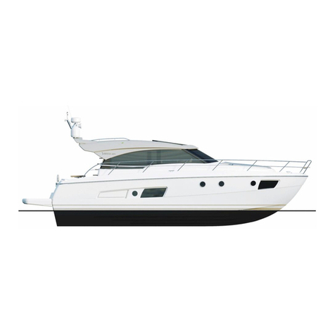
Cruiser Yachts 5000 Series User manual

5000 Series Boats
Table of Contents
1. Introduction ............................................................................ 1-1
2. Specifications and General Layout ..................................... 2-1
3. Controls and Indicators ........................................................ 3-1
4. Principles of Operation ......................................................... 4-1
5. Getting Underway .................................................................. 5-1
6. Periodic Checks and Services ............................................. 6-1
7. Storage for Extended Lay-Up ............................................... 7-1
8. General Maintenance ............................................................ 8-1
9. Accessory Items .................................................................... 9-1
10. Troubleshooting .................................................................. 10-1
i
5000 Series
Downloaded from Cruisers Owners Forum
http://www.CruisersOwnersForum.com

5000 Series
ii 5000 Series
Downloaded from Cruisers Owners Forum
http://www.CruisersOwnersForum.com

Section 1 – Introduction
WELCOME ABOARD ............................1-2
SKIPPER’S KIT .....................................1-2
Owner’s Manual................................1-2
Owner’s Manuals, Envelopes ...........1-3
AVAILABLE FEATURES .......................1-3
WARRANTY INFORMATION.................1-3
Dealership Responsibilities ..............1-3
Your Responsibilities ........................1-4
Warranty Service ..............................1-4
1-1
5000 Series
Downloaded from Cruisers Owners Forum
http://www.CruisersOwnersForum.com

WELCOME ABOARD!!
Welcome to the Cruiser Yachts family of
happy boat owners.
First off, we wish to thank you for making
our 5000 Series Boat your recreational
choice for boating enjoyment. Extensive
design and engineering research went into
the development of the 5000 Series Boat;
and we feel that there is a beautiful balance
between structural integrity and creature
comforts.
You should know that your boat was manu-
factured by trained craftsmen
in the tradition of meeting or exceeding
existing safety and quality standards estab-
lished by the U.S. Coast Guard and the
Boating Industry of America.
Cruisers Yachts has been manufacturing
boats for over 40 years. We take pride in our
craftsmanship and hull performance. We are
confident you will enjoy the ride. For you, the
Cruisers Yachts name is your assurance
that your boat will hold its value while provid-
ing many years of boating pleasure. We
have made a commitment to this industry
and are glad to have you as a partner.
Congratulations on your choice – let us
know if we can be of further service.
SKIPPER’S KIT
The skipper’s kit contains the 5000 Series
owner’s manual. Along with the owner’s
manual, there is an envelope which includes
information about onboard systems and
components furnished by suppliers other
than Cruisers Yachts.
Owner’s Manual, 5000 Series
Boats
Spend some time looking through this man-
ual. It contains information concerning the
operation and care of your boat. The
descriptions contained within the manual will
introduce you to the features of the boat,
and provide you with a general knowledge of
how the equipment works. The manual is
divided into ten sections, and each section
is introduced by a table of contents to help
you quickly find needed information.
Become familiar with the material in each
section before operating your boat.
Throughout the manual you will come
across safety precautions labeled
WARNING or CAUTION.
WARNINGS indicate hazards or unsafe
practices which could result in personal
injury or death. CAUTIONS indicate situa-
tions which could result in damage to the
boat and its various systems.
!
!
Section 1 contains a description of the skip-
per’s kit and information about the warranty.
Section 2 contains boat specifications such
as dimensions and capacities. There are
also layout diagrams to introduce you to
floorplans as well as the locations of various
components.
Section 3 contains descriptions of all the
controls and indicators on the dash of the
helm.
Section 4 contains principles of operation
for the major systems onboard the 5000
Series Boats. Look in this section for electri-
cal schematics.
Section 5 contains instructions for operating
the boat The section begins with safety infor-
mation which is “must” reading.
Section 6 contains maintenance instructions
for services that need to be performed on a
regular basis.
Section 7 contains instructions for storing
the boat for extended periods of time, and
prep instructions for after storage.
Section 8 contains information about the
care of your boat, and how to repair minor
damage.
5000 Series
1-2 5000 Series
Downloaded from Cruisers Owners Forum
http://www.CruisersOwnersForum.com

Section 9 contains information about the
standard and optional accessory items
which complement your new Cruisers Yachts
boat.
Section 10 contains a brief troubleshooting
section.
Owner’s Manuals and
Pamphlets, Systems and
Components (Envelopes)
Spend some time becoming familiar with all
the information contained in the envelope,
because this information is not duplicated in
your 5000 Series Owner’s Manual. Besides
containing separate warranty information,
the envelope contains manuals and pam-
phlets which provide important safety, oper-
ating, and maintenance instructions for
those systems and components not manu-
factured by Cruisers Yachts. Depending on
the options you chose the envelope may
contain some or all of the following manuals:
AVAILABLE FEATURES
●Engine Operation/Maintenance
- Electric Schematic
●Hydraulic Steering Manual
●RACOR Fuel Filter/Water Separator
●Electric Stove
●AC Powered Battery Charger Manuals
●Water Heater Manual
●Trim Planes Manual
●Refrigerator/Freezer User Manual
●Generator Operation/Maintenance
- Electrical Schematics
- Service Centers Directory
●Electric Anchor Windlass
Operation/Maintenance Manual
●Air Conditioner Information Packet
●Stereo System Operation Manual
●Compass Manual
●Microwave User Manual
●Marine Toilet Manual
●Halon Automatic Fire Extinguisher
Information
●Carbon Monoxide (CO) Detector
Handbook
●Ice Maker Manual
●Shaft Logs Manual
●Washer/Dryer Manual
●Bow Thruster Manual
●Hydraulic Swim Platform Manual
●Central Vacuum Manual
WARRANTY INFORMATION
Warranties for onboard systems and compo-
nents furnished by suppliers other than
Cruisers Yachts, are located in the envelope
inside the skipper’s kit. Your Cruisers Yachts
Dealer will go through these with you. It is
your responsibility to fill out any warranty
registration that may be required.
The warranty provided by Cruisers Yachts is
printed on the last page of this manual. You
and the Cruisers Yachts Dealership have
certain responsibilities to fulfill to keep the
warranty in force.
Dealership Responsibilities
1. The dealer will discuss the terms of all
warranties, and stress the importance of
registering warranties with the appropri-
ate manufacturers.
2. The dealer will provide instruction for
obtaining warranty service.
3. The dealer will go over the predelivery
service record with you, and then sign it
to certify that all work has been accom-
plished.
4. The dealer will provide you with a thor-
ough instruction in the operation of your
boat and all its systems.
1-3
5000 Series
Downloaded from Cruisers Owners Forum
http://www.CruisersOwnersForum.com

Your Responsibilities
1. Sit down with the dealer and go over all
warranties. Fill in the Cruisers Yachts lim-
ited warranty registration card which is
located in an envelope inside the
skipper’s kit. Keep a record of the hull
number for future reference.
2. Inspect the boat at the time of delivery to
ensure that all systems are
operating properly.
3. Sit down with the dealer and go over the
predelivery service record. Sign this
record to indicate that it has been
explained to you.
4. Operate all equipment per the manufac-
turer’s instructions.
5. Cruisers Yachts recommends that you
refer to your engine warranty for initial
inspection and service requirements.
6. Perform or provide for the appropriate
periodic maintenance outlined in the
owner’s manuals and service guides.
Warranty Service
You are entitled to all the benefits and ser-
vices set down in the warranties. If a prob-
lem arises with your Cruisers Yachts boat as
a result of workmanship or materials, con-
tact your Cruisers Yachts dealer as soon as
possible. Please have your hull identification
number, and necessary model numbers on
hand for the items that may need service or
repair. Your hull identification number is
located below the rub rail on the starboard
side of the transom.
5000 Series
1-4 5000 Series
Downloaded from Cruisers Owners Forum
http://www.CruisersOwnersForum.com

Section 2 – Specifications and Layout
2-1
5000 Series
SPECIFICATIONS ............................... 2-2
ENGINES ............................................. 2-2
GENERAL LAYOUT ............................ 2-3
Downloaded from Cruisers Owners Forum
http://www.CruisersOwnersForum.com

SPECIFICATIONS
Measurements
L.O.A with Integrated Swim Platform.................................................................... 49'6" / 15.1 m
Beam ....................................................................................................................... 15'6" / 4.7 m
Approximate Weight (Diesel).......................................................................... 30,000 / 17,195 K
Fuel Capacity (U.S. Gallons) ................................................................................. 600 / 2,268 L
Cabin Headroom....................................................................................................... 6'6" / 2.0 m
Height – Keel to Top of Windshield......................................................................... 15'3" / 4.7 m
Height – Keel to Top of Arch (Radar Included) ...................................................... 19'0" / 5.8 m
Draft........................................................................................................................... 3'5" / 1.1 m
Bridge Clearance (Radar Pedestal Included)......................................................... 16'5" / 5.1 m
Water System Capacity (U.S. Gallons)..................................................................... 150 / 567 L
Waste Holding Capacity (U.S. Gallons)..................................................................... 100 /377 L
Sleeping Accommodations.......................................................................................... 6 persons
ENGINES
Caterpillar
T 3126TA Diesel, 420 HP (313 kW), IB
T 3176C Diesel, 600 HP (448 kW), IB
Detroit Diesel Volvo
T TAMD73P Diesel, 430 HP (316 kW), IB
T 6V-92TA Diesel, 550 HP (410 kW), IB
T 6V-92TIA DDEC Diesel, 625 HP (466 kW), IB
T TAMD122 Diesel, 610 HP (449 kW), IB
5000 Series
2-2 5000 Series
Downloaded from Cruisers Owners Forum
http://www.CruisersOwnersForum.com

CSR173-4
22 18
1
3
23
SIDE
VIEW
25
26 5
4
921057 27
6917
13
15
16
14
11
13
21
1924 20 12
GENERAL LAYOUT
1. Recess Anchor Roller
2. Starboard Nav Light
3. Starboard Bow Cleat
4. Compass
5. Amidship Cleats
6. Horn
7. Helm Station
9. Boarding Lights
10. Water Fill
11. TV-Telephone Receptacle
12. Fuel Fill
13. Stern Cleats
14. Shore Power
15. Boarding Ladder
16. City Water
17. Cockpit Shower
18. Stern Light
19. AC Outlet - GFI
20. Waste Plate
21. Port Boarding Light
22. Mast Light
23. Port Bow Cleat
24. Port Nav Light
25. Rope Locker/Windlass
26. Spotlight
27. Wet Bar
2-3
5000 Series
Downloaded from Cruisers Owners Forum
http://www.CruisersOwnersForum.com

5000 Series
2-4 5000 Series
CSR173-5
15C
19C 18C
22C
7C 6C 5C 8C
20C
GENERAL LAYOUT
1C. Hanging Locker
2C. Starboard Vanity
3C. Starboard Head
4C. Starboard Shower
5C. Galley
6C. Stove
7C. Refrigerator
8C. TV
9C. Aft Stateroom
10C. ASR TV
11C. Port Vanity
12C. Port Shower
13C. Port Head
14C. Hanging Locker
15C. Dinette
16C. TV (Optional)
17C. FSR Birth
18C. Helm Station
19C. Compass
20C. Chart Cover
21C. Washer/Dryer
22C. Microwave
23C. Master Stateroom
Downloaded from Cruisers Owners Forum
http://www.CruisersOwnersForum.com

GENERAL LAYOUT
CSR173-6
21C6
9C
1C
10C
3C
1
3
44
45
47
4C
2C
52
17C
49
16C
1C
12C 13C 16C 2550 8
714C
23C
54
11C
48 42 36
38 37
25 33
22
17
28
26
30
31
27
20
24 (CAT)
34
21
16
13 15 23
35
2 (CAT)
2 (VOLVO)
40
53
24 (VOLVO)
19
46
4
9
11,12
18
43
55
1. Shower Sump
2. Fwd Bilge Pump
3. Vacuflush Pumps
4. Water Tanks (150 gallon)
5. Head Tank Vent
6. Water Tank Vent
7. Head Tank
8. Water Heater
9. Fresh Water Pump
11. Y Valve
12. Macerator
13. Stbd Engine Seacock
15. Stbd Engine Strainer
16. Stbd Engine
17. Aft Bilge Pump
18. Fuel Water Separator
(Engines)
19. Fuel Selector Valves
20. Stbd Engine Muffler
21. Blowers
22. Generator
23. Generator Muffler
24. Battery #1
25. Battery #4
26. Battery Isolator
27. Battery Charger 12V/24V
28. Bonding Strip
30. Trim Tab Pump
31. Battery #3
32. Battery #2
33. Port Engine Muffler
34. Fuel Water Separator
(Generator)
35. Port Engine
36. Generator Strainer
37. Oil Change Unit
38. Port Engine Strainer
39. Transom Zinc Plate
40. Generator Seacock
42. Port Engine Seacock
43. Halon Fire Extinguisher
44. AC Strainer
45. AC Seacock
46. Transducer Depth Finder
(Bridge)
47. AC Pump
48. AFT AC Unit
49. Forward AC Unit
50. Port Fuel Tank
51. Stbd Fuel Tank
52. Bow Thruster
53. Bow Thruster Battery
54. Mid AC Unit
55. Transducer Depth (Salon)
2-5
5000 Series
Downloaded from Cruisers Owners Forum
http://www.CruisersOwnersForum.com

5000 Series
2-6 5000 Series
CSR173-7
86 88 89 90
91
93
79
92
94
94
87
87
27
82
44 69
68
67
66
65
48
49
45
47
46
83
34
29
59 26
37
36
21
21
35
35
20
17
19
18
3
2
25
4
5
1
9
24
6
7
64 15
14
51
77
77
86
41
42
43
38
31
28 33
30
50
60
77
13
15
10
23
22 23
23
77 8
79
77
11
12
39
75
81 77 58
74
76
71
72
73
40
70
A
80
96
63
55
57
54
52
53
56
78
VIEW A
1. Rudders
2. Generator
3. House Battery
4. Rudder Indicator
5. Tiller Arms
6. Tie Bar
7. Steering Cylinder
8. Generator Muffler
9. Trim Tab Pump
10. 12 Volt Battery Charger
11. 24 Volt Battery Charger
12. Hydraulic Swim Platform Lift Pump
13. Dockside Cord Holder
14. Generator Battery
15. Port Engine Battery
16. Port Engine Battery
17. Starboard Engine Battery
18. Starboard Engine Battery
19. Struts
20. Generator Fuel Filter
21. Shaft Assembly
22. Blowers
23. Vents
24. Bonding Strip
25. Port Engine
26. Starboard Engine
27. Starboard Seacock
28. Port Seacock
29. Flybridge Transducer
30. Lower Station Transducer
31. Generator Seacock
32. Halon Fire Extinguisher
33. Port Engine Water Strainer
34. Starboard Engine Water Strainer
35. Engine Coolant Recovery Tank
36. Port Oil Filter
37. Starboard Oil Filter
38. Generator Strainer
39. Shift Control Box
GENERAL LAYOUT DETROIT DIESEL
Downloaded from Cruisers Owners Forum
http://www.CruisersOwnersForum.com

GENERAL LAYOUT VOLVO
2-7
5000 Series
CSR173-8
86 88 89 90
91
93
92
94
94
87
87
27
82
44
69
68
67
66
65
48
49
45
47
83
29
59 26
34
18
84
21
21
35
35 41
61
20
17
19
18
3
2
25
4
5
1
9
24
6
7
64
14
51
43
38
31
28
34
30
50
60 13
15
10
23
22 23
23
8
79
12
39
32
75
58
74
76
71
72
73
40
70
A
62
63
15
57
52
53
54
56
VIEW A
42
40. Fuel Tank Filter
41. Port Engine Muffler
42. Starboard Engine Muffler
43. Starboard Fuel Tank
44. Port Fuel Tank
45. Air Conditioner
46. Detroit Engine Run Interface
Module
47. Bow Thrusters Battery
48. Battery Switch
49. Hot Water Heater
50. Power Steering Fluid Tank
51. Aft Bilge Pump
52. Ground Buss
53. 125 Amp Windlass Fuse
54. 300 Amp House Fuse
55. Isolator 240 Volt
56. Isolator 12 Volt
57. Positive Buss
58. 80 Amp Power Solenoid
59. Starboard Fuel Filter
60. Steering Filter
61. Steering Cooler
62. Holding Tank Vent Filter
63. Generator Battery Switch
64. Oil Change Pump
65. Port Fuel Sender
66. Port Fuel Fill
67. Port Fuel Vent
68. Port Fuel Feed
Downloaded from Cruisers Owners Forum
http://www.CruisersOwnersForum.com

GENERAL LAYOUT CATERPILLAR
5000 Series
2-8 5000 Series
CSR173-9
86 88 89 90
91
93
92
94
94
87
87
27
52
44 69
77
68
67
66
65
48
45
47
83
29
34
32 26
21
21
35
35
63
20
17
19
18
3
2
25
4
5
1
9
24
6
7
64
15
16
14 19
41
42
43
76
38
31
28 33
30
50
77
13
55
57
54
52
53
56
78
15
10
23
22 23
23
8
79
7777 12
39
40
75
58
74
71
72
73
82
70
VIEW A
A
69. Port Fuel Return
70. Starboard Fuel Sender
71. Starboard Fuel Fill
72. Starboard Fuel Vent
73. Generator Return
74. Generator Fuel Feed
75. Starboard Engine Feed
76. Starboard Engine Return
77. Bilge Lights
78. Battery Equalizer
79. 30 Amp Fuse for Amplifier
80. Port Exhaust Seacock (Detroit)
81. Starboard Exhaust Seacock
(Detroit)
82. Port Shift Control Box
83. Crossover
84. Port Shift Acuator
85. Starboard Shift Acuator
86. Bow Thruster
87. Vacu-Flush Pumps
88. Shower Sump
89. Waste Holding Tank
90. Forward Bilge Pump
91. Air Conditioner Seacock
92. Air Conditioner Strainer
93. Air Conditioner Pump
94. Water Tanks
Downloaded from Cruisers Owners Forum
http://www.CruisersOwnersForum.com

3-1
5000 Series
Section 3 – Dash Controls and Indicators
DASH LAYOUT ...................................... 3-2
Engine Tachometers......................... 3-2
Synchronizer Gauge......................... 3-2
Transmission Oil Pressure Gauges... 3-2
Compass .......................................... 3-2
Engine Hourmeters .......................... 3-2
Fuel Gauges..................................... 3-2
Engine Temperature Gauges............ 3-2
Oil Pressure Gauges........................ 3-2
Rudder Angle Indicator .................... 3-3
Voltmeter .......................................... 3-3
Steering Wheel................................. 3-3
Halon Display Unit............................ 3-3
Throttle Controls............................... 3-3
Accessory Switch and Breaker .........3-3
Spreader Lights and Breaker ........... 3-3
Boarding Lights Switch and Breaker... 3-3
Navigation/Anchor Lights Switch
and Breaker................................... 3-3
Bilge Lights Switch and Breaker ...... 3-3
FWD Bilge Pump and Breaker......... 3-4
Mid Bilge Pump and Breaker ........... 3-4
Aft Bilge Pump and Breaker............. 3-4
Tr im Tab Controls and Breaker......... 3-4
Depth Finder..................................... 3-4
Helm Seat......................................... 3-4
Windlass Control and Breaker ......... 3-4
Horn Switch and Breaker ................. 3-4
Spotlight Controls and Breaker ........ 3-4
Windshield Washers......................... 3-5
Wipers Switch and Breakers ............ 3-5
Defogger and Breaker ...................... 3-5
Electronics........................................ 3-5
12 Volt Outlet .................................... 3-5
Blowers Switch and Breaker ............ 3-5
Ignition Switches .............................. 3-5
Start Switches (Diesel)..................... 3-6
Engine Shutdown Switches.............. 3-6
Caterpillar Electronic Instrumentation
... 3-6
Sync Slave........................................ 3-6
Slow Vessel Mode ............................ 3-6
Emergency Shutdown ...................... 3-6
English/Metric................................... 3-6
Port and Stbd Scroll ......................... 3-6
Detroit Diesel D-Dec System ........... 3-6
CATERPILLAR 3126 ............................. 3-7
DETROIT DIESEL VOLVO 73 SERIES... 3-8
DETROIT DIESEL.................................. 3-9
CATERPILLAR 3176 ........................... 3-10
DASH PANEL BREAKER BOX ........... 3-11
Downloaded from Cruisers Owners Forum
http://www.CruisersOwnersForum.com

DASH LAYOUT
Key to Dash Layout
1 and 3 —ENGINE TACHOMETERS
Item 1is the port engine tachometer, and
item 3is the starboard engine tachometer.
The tachometers register engine crankshaft
RPM’s. Propeller shaft RPM’s are approxi-
mately one half of engine crankshaft RPM’s.
Refer to your engine owner’s manual for the
appropriate engine speed.
2 —SYNCHRONIZER GAUGE
The synchronizer gauge compares engine
speeds. When the needle points to zero, it
means the port and starboard engines are
running in sync with each other. When the
needle points to the left or the right of zero,
it means one engine is running at a higher
RPM than the other. Correct the situation by
either increasing or decreasing the throttle
on one engine or the other until the gauge
indicates zero.
4 and 5 —TRANSMISSION OIL
PRESSURE GAUGES
Item 4is a transmission oil pressure gauge
for the port engine transmission, and item 5
is a transmission oil pressure gauge for the
starboard engine transmission. The trans-
missions are hydraulically operated, and ide-
ally should read between 300 and 320 psi.
Small fluctuations are normal, but major
variations may indicate trouble. If pressure
changes radically, shut engines off and con-
sult your dealer.
6 —COMPASS
The compass has not been compensated.
The compensating should be performed by
a qualified compass adjuster. After the com-
pass has been adjusted, do not allow any
iron or steel objects to be placed in its
vicinity - even temporarily. Refer to the
owner’s manual included in the Skipper’s Kit
for detailed information.
7 and 8 —ENGINE HOURMETERS
Item 7is the port engine hourmeter, and
item 8is the starboard engine hourmeter.
The hourmeters register accumulated
engine operating time, and are activated
when the ignition switch is in the “ON”posi-
tion. Be aware that time will be logged when
ignition switch is “ON,”even when the
engines are off. Use the engine hourmeters
to keep accurate logs for scheduled mainte-
nance, and to determine rate of fuel con-
sumption in gallons per hour.
9 and 17 —FUEL GAUGES
IMPORTANT
Do not rely on the accuracy of
gauges. Readings are only approxi-
mate, and should always be com-
pared to the hours of use multiplied
by the known fuel consumption
(GPH).
Item 9is the port fuel tank gauge and item
17 is the starboard fuel tank gauge. The
gauges indicate the approximate amount of
fuel in each of the tanks.
10 and 11 —ENGINE TEMPERATURE
GAUGES
Item 10 is a temperature gauge for the port
engine, and item 11 is a temperature gauge
for the starboard engine. The gauges indi-
cate cooling water temperature inside the
engines. Normally the gauge will register
between 170°F and 195°F. Consult engine
owner’s manual if gauge registers outside of
this range.
12 and 14 —OIL PRESSURE GAUGES
Item 12 is an oil pressure gauge for the port
engine, and item 14 is an oil pressure gauge
for the starboard engine. These gauges indi-
cate the pressure of the lubricating oil inside
the engine. Make a note of the oil pressure
reading when the boat is new; this can be
considered your engine’s normal oil pres-
sure. Fluctuations will occur in the pressure
under different operating speeds, but major
deviations may signal problems. If pressure
stops radically or is not registering, turn the
engines off and consult your dealer.
5000 Series
3-2 5000 Series
Downloaded from Cruisers Owners Forum
http://www.CruisersOwnersForum.com

13 — RUDDER ANGLE INDICATOR
The rudder angle indicator shows the posi-
tion of the rudder in relation to the centerline
of the boat. This instrument is used to aid in
low speed maneuvering. Since a yacht of
this size responds slowly to the rudder at
slow speeds, the rudder angle indicator
gives a quick reference to the amount of
rudder being used in a turn.
15 and 16 — VOLTMETER
Item 15 is a voltmeter for the port engine
cranking battery, and item 16 is a voltmeter
for the starboard engine cranking battery.
Normal operating voltage, when engine is at
1000 plus RPM’s, is between 12.0 and 15.5
volts. Higher or lower readings would indi-
cate that there is a problem. Refer to your
engine owner’s manual for details, and refer
the problem to your Cruisers Yachts dealer.
18 — STEERING WHEEL
The steering wheel is hydraulically linked to
the rudders for ease of operation.
See Section 4, Principles of Operation for
detailed information on the steering system.
19 — HALON DISPLAY UNIT
The display unit has an indicator lamp to
indicate Halon automatic fire extinguisher
status. The lamp should glow when the igni-
tion switch is in the “ON” position indicating
a charged system. Should the system dis-
charge, the lamp will not glow.
See Halon Owner’s Manual in the Skipper’s
Kit for complete details.
20 and 21 — THROTTLE CONTROLS
Item 20 is the throttle control lever for the
port engine, and item 21 is the throttle con-
trol lever for the starboard engine. Pull the
levers their full travel toward you for engine
idle, and gradually increase the speed to full
throttle by pushing the levers away from you.
22, 23, 35, 36, 37, 39, 40, 41, 43, 44, 45, 52,
53, 64, 65, 66, 67 and 68 —
ACCESSORY SWITCH AND BREAKER
24 — SPREADER LIGHTS AND
BREAKER
Push top of rocker switch to turn on spread-
er lights that are located above the patio
doors, in the flybridge overhang. Push the
bottom of switch to turn them off. The lights
are protected by a resettable circuit breaker
located in the breaker panel.
25 and 46 — BOARDING LIGHTS
SWITCH AND BREAKER
Push the top of the switch to turn on the
cabin side boarding lights and the bottom of
the switch to turn them off. The lights are
protected by a resettable circuit breaker
located in the breaker panel.
26 and 47 — NAVIGATION/ANCHOR
LIGHTS SWITCH AND BREAKER
The light switch is a three position switch.
The middle position is “OFF.” Push the top
of the rocker switch to operate the naviga-
tion lights. The navigation lights are the port
and starboard side lights, the stern light, and
the mast light. Push the bottom of the rocker
switch to operate the anchor light. The lights
are protected by a resettable circuit breaker
located in the breaker panel.
27 and 48 — BILGE LIGHTS SWITCH
AND BREAKER
Push the top of rocker switch to turn the
bilge lights on and the bottom of switch to
turn them off. The lights are protected by a
resettable circuit breaker located in the
breaker panel.
3-3
5000 Series
Downloaded from Cruisers Owners Forum
http://www.CruisersOwnersForum.com

to turn the pump off. Bilge pump is protected
by a resettable circuit breaker located in the
breaker panel.
31, 32, 61 and 62 — TRIM TAB
CONTROLS AND BREAKER
IMPORTANT
Push the trim tab rocker switches in
half second bursts. Holding the rock-
ers down too long will overtrim the
boat.
The trim tab rocker switches are used to
correct the trim of your boat while you are
underway. To trim the bow of your boat
down, push the top halves of both switches.
To trim the bow of your boat up, push the
bottom halves of both switches. Refer to
Suggested Operating Techniques in Section
5 for detailed information. The trim tabs are
protected by a resettable circuit breaker
located in the breaker panel.
33 and 54 — DEPTH FINDER
The depth finder can be turned ON by push-
ing the top of the adjacent accessory switch.
Push the bottom of the switch to turn it OFF.
34 — HELM SEAT
This switch adjusts the flybridge helm seat.
This is a three-position spring loaded switch.
Push on the top to move the seat forward,
push on the bottom to move the seat aft.
38 and 59 — WINDLASS CONTROL AND
BREAKER
The main windlass breaker is located in the
cabin on the AC-DC panel. Push the top of
the windlass switch to lower the anchor and
the bottom to retrieve the anchor. The wind-
lass is protected by a resettable circuit
breaker located in the breaker panel. See
Windlass Owner’s Manual, located in the
Skipper’s Kit for details on operation and
maintenance.
42 and 63 — HORN SWITCH AND
BREAKER
Press the top of the rocker switch to sound
the horn. The horn is protected by a reset-
table circuit breaker located in the breaker
panel.
55 and 56 — SPOTLIGHT CONTROLS
AND BREAKER
The switch in the middle is a three position
toggle switch. It controls the light mounted
on the pulpit railing. Move the switch down
for floodlight affect, to the middle for off, and
up for the spotlight effect. The joystick to the
left controls the movement of the light and
the knob to the right controls the speed at
which the light will move. The spotlight is
protected by a resettable circuit breaker
located in the breaker panel.
5000 Series
3-4 5000 Series
28 and 49 — FWD BILGE PUMP AND
BREAKER
Fwd bilge pump is located below the mat-
tress in the master stateroom. Bilge pump
operation is automatic, but can be controlled
manually. To start the mid bilge pump push
the top of the rocker switch. Push the bottom
to turn the pump off. Bilge pump is protected
by a resettable circuit breaker located in the
breaker panel.
NOTE
The computerized, automatic sys-
tem assures that the vessel is
always pumped out and that the
pump does not run needlessly. This
system performs a “self-cycle” every
2.5 minutes.
29 and 50 — MID BILGE PUMP AND
BREAKER
Bilge pump operation is automatic, but can
be controlled manually. To start the bilge
pump, push the top of the rocker switch.
Push the bottom to turn the pump off. Mid
bilge pump is protected by a resettable cir-
cuit breaker located in the breaker panel.
30 and 51 — AFT BILGE PUMP AND
BREAKER
Bilge pump operation is automatic, but can
be controlled manually. To start the engine
compartment bilge pump push the top of the
rocker switch. Push the bottom of the switch
Downloaded from Cruisers Owners Forum
http://www.CruisersOwnersForum.com

5000 Series
NOTE
To operate the spotlight, the station
switch at the lower helm must be
positioned to the lower helm.
57 —WINDSHIELD WASHERS
Turn freshwater system ON. Push and hold
the spring-loaded switch to wash the wind-
shield. Release the switch to stop.
58 —WIPERS SWITCH AND BREAKERS
Push the top of the rocker switch to turn
both wipers on and push the bottom to turn
the wipers off. The wipers are protected by a
resettable circuit breaker located in the
breaker panel.
60 —DEFOGGER AND BREAKER
This two position switch defogs the wind-
shield. Push on the top to turn defog ON.
Push on the bottom to turn defog OFF.
Defogger switch is protected by a resettable
circuit breaker located in the breaker panel.
69 and 70 —ADDED ELECTRONICS
These switches are for optional dealer
installed electronics. See your dealer for
further information.
71 —12 VOLT OUTLET
This receptacle provides 12 volt DC power
to portable accessories such as cellular tele-
phones.
72 —BLOWERS SWITCH AND BREAKER
WARNING
Gasoline vapors can explode!
Always check engine compart-
ment for the presence of gasoline
odor. Operate blowers for at least
four minutes before cranking
engine. Run blowers when operat-
ing engines below cruising speed.
Push the top of the rocker switch to turn
blowers on, and at the bottom to turn them
off. Blower circuit protection is provided by a
resettable circuit breaker located in the
breaker panel.
73 AND 74 IGNITION SWITCHES
Volvo with Volvo Control System –Keys
are at each station. See the Volvo Owner’s
Manual for more information.
Volvo with Twin Disc Control System –
Ignition keys and breakers are located on the
AC/DC panel. Turn the keys and breakers
ON. The ignition switch can now be activated.
!
To Start:
1. Push the top of the ignition switch.
2. Push the ACTIVATE button on the con-
trol head.
3. Push the top of the ENGINE START
switch.
4. Hold the ACTIVATE button on the control
head until the NEUTRAL light on the top
of the control flashes. This will allow
throttle only.
5. Bring the control back to NEUTRAL and
it will return to the Throttle/Shift mode.
To Stop:
Push the EMERGENCY SHUTDOWN
switch. After the engine stops, push the bot-
tom of the ignition switch to turn OFF. Turn
off the keys at the AC/DC panel if you are
leaving the boat.
Caterpillar —Ignition keys and breakers
are located on the AC/DC panel. Turn the
keys and breakers ON. The ignition switch
can now be activated at either station.
To Start:
6. Push the top of the ignition switch.
7. Push the ACTIVATE button on the con-
trol head.
3-5
Downloaded from Cruisers Owners Forum
http://www.CruisersOwnersForum.com

8. Push the top of the ENGINE START
switch.
9. Hold the ACTIVATE button on the control
head until the NEUTRAL light on the top
of the control flashes. This will allow
throttle only.
10. Bring the control back to NEUTRAL and
it will return to the Throttle/Shift mode.
To Stop:
Push the bottom of the ignition switch. Turn
off the keys at the AC/DC panel if you are
leaving the boat.
75 and 76 —START SWITCHES (Diesel)
Item 75 is the start switch for the diesel
engine, portside. Item 76 is the start switch
for the diesel engine, starboard side.
The switch is three position: off, run, and
start. There is no accessory position.
Each switch is electrically protected by a
resettable circuit breaker located in the
breaker panel.
77 and 78 —ENGINE SHUTDOWN
SWITCHES
The red 2 position rocker switches are use
to shut the engines down (See Section 4 for
more information).
79 —CATERPILLAR ELECTRONIC
INSTRUMENTATION
Refer to the information in the Skipper’s Kit.
80 –SYNC SLAVE
This three position switch allows you to acti-
vate the sync system and choose the mas-
ter engine. Push down to select the star-
board engine or up to select the port engine.
The center position if OFF.
81 –SLOW VESSEL MODE
This switch is used in slow speed operations
such as docking and allows the engines to
be slowed to 400 RPM for short periods of
time. Refer to the Skipper’s Kit for more
information.
82 and 83 EMERGENCY SHUTDOWN
Volvo —The emergency shutdown switch is
used to stop the engines at all times. The
ignition switches are left on and the emer-
gency shutdown is used to stop the engines.
After the engine stops the ignitions switch
can be turned OFF.
Caterpillar —The engines are normally
stopped with the ignition switches. The
emergency shutdown is to be used ONLY in
an emergency. After use of the emergency
shutdown switch, no reset is required.
Detroit D-DEC —The engines are normally
stopped with the ignition switches. The
emergency shutdown is to be used ONLY in
an emergency. After use of the emergency
shutdown switch, the flapper valves on the
turbochargers must be reset. Refer to the
Skipper’s Kit for more information.
84 –ENGLISH/METRIC
This switch is included with the Caterpillar
electronic instrumentation system and will
switch the units displayed between English
or metric. Push the button to switch between
the two.
85 and 86 PORT AND STARBOARD
SCROLL
This switch is included with the Caterpillar
electronic instrumentation system and
allows you to page through the various
options on the display. Refer to the Skipper’s
Kit for more information.
87 —DETROIT DIESEL D-DEC SYSTEM
Refer to the Skipper’s Kit for more informa-
tion.
5000 Series
3-6 5000 Series
Downloaded from Cruisers Owners Forum
http://www.CruisersOwnersForum.com
Table of contents
Popular Boat manuals by other brands
J&J Amusements
J&J Amusements Bumper Boat 2014 Service manual

Bavaria Yachts
Bavaria Yachts BAVARIA 44 - 3 cabins Manual for owners and skippers
West Wight Potter
West Wight Potter POTTER 15 user guide
Mercury
Mercury Ocean Runner 290 owner's manual
Cobalt Digital Inc
Cobalt Digital Inc 323 Day Cruiser owner's manual
Yamaha
Yamaha SHVO owner's manual


