ABACUS HL250 User manual

Product Manual
November 2022
.
Part No: INS-HL
High Lume (HL) Masts
Applicable products:
•HL250
•HL250E
•HL330
•RLH5
•RLH7
•RLH11
WE STRONGLY RECOMMEND THAT THESE
INSTRUCTIONS ARE READ CAREFULLY BEFORE
ATTEMPTING TO INSTALL, OPERATE AND MAINTAIN
THIS EQUIPMENT

Abacus Lighting, Sutton-in-Ashfield, Nottinghamshire, NG17 5FT, England. Tel: (+44) 01623 511111, www.abacuslighting.com
1
Product Manual
November 2022
1. Safety ........................................................................................................................ 2
2. Installation................................................................................................................ 3
2.1. General ....................................................................................................................................... 3
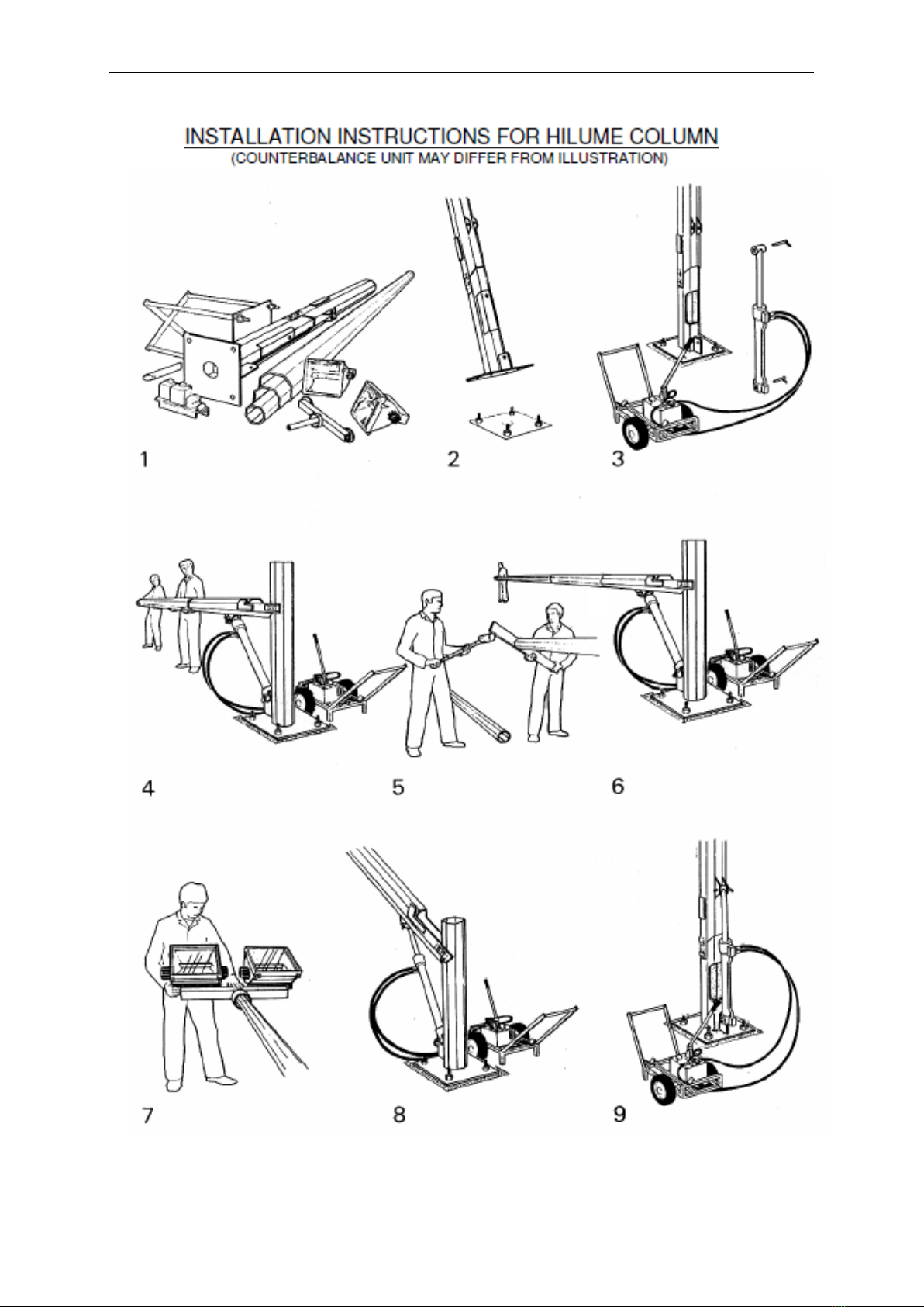
2.2. Mast Positioning ........................................................................................................................ 3
2.3. Mast Assembly ........................................................................................................................... 4
3. Operation .................................................................................................................. 7
3.1. General ........................................................................................................................................7
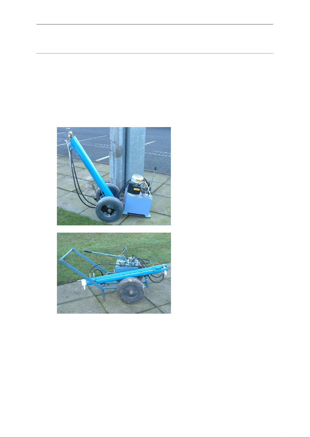
3.2. Moving the Counterbalance (RLH5 only) ................................................................................ 8
3.3. Checks Before Use ..................................................................................................................... 8
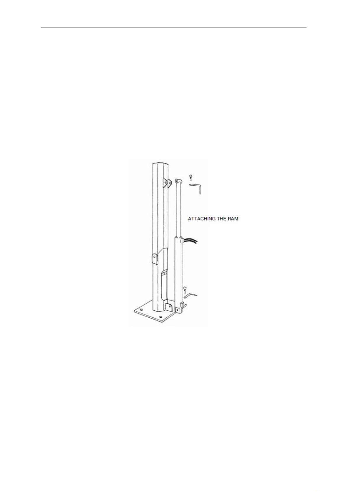
3.4. Fitting the Ram to the Mast ...................................................................................................... 9
3.4.1. HL250 Mast (RLH5 only) ..................................................................................................... 9
3.4.2. HL250 Mast (RLH7 only)...................................................................................................... 9
3.4.3. HL330 Mast ........................................................................................................................... 9
3.5. Lowering the Mast ....................................................................................................................10
3.6. Raising the Mast ....................................................................................................................... 11
3.7. Removing the Ram ...................................................................................................................12
3.7.1. HL250 Mast ..........................................................................................................................12
3.7.2. HL330 Mast ..........................................................................................................................12
3.7.3. Depressurising Procedure ....................................................................................................12
4. Maintenance ........................................................................................................... 14
4.1. Mast Type Identification ..........................................................................................................14
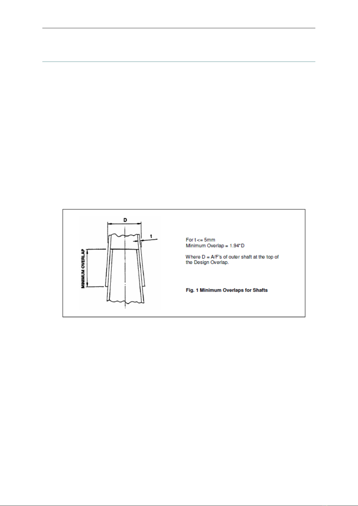
4.2. Masts ......................................................................................................................................... 15
4.2.1. Every Time the Mast is Lowered.......................................................................................... 15
4.2.2. Every 12 Months ................................................................................................................... 15
4.2.3. As Required ...........................................................................................................................15
4.3. Counterbalances .......................................................................................................................16
4.4. Hydraulic Hoses .......................................................................................................................19
5. EN 1090 Certificate of Conformity ..........................................................................20
6. CE Marking ............................................................................................................. 21
7. Environmental Advice............................................................................................. 22
7.1. General ..................................................................................................................................... 22
7.2. Information.............................................................................................................................. 22
8. Equipment Classification ........................................................................................ 23

Abacus Lighting, Sutton-in-Ashfield, Nottinghamshire, NG17 5FT, England. Tel: (+44) 01623 511111, www.abacuslighting.com
2
1. Safety
WE STRONGLY RECOMMEND THAT THESE REQUIREMENTS ARE READ
CAREFULLY BEFORE ATTEMPTING TO INSTALL, OPERATE AND MAINTAIN THIS
EQUIPMENT.
i) It is essential that all operators are trained and authorised in the safe use of the counterbalance unit.
ii) It is recommended that certified operator training be carried out by Abacus personnel.
iii) The counterbalance unit must only be used for the purpose intended, as described in these
operating instructions. Abacus Lighting Limited will not be held responsible for any misuse or abuse
of the unit. Similarly no repair, modification or maintenance work, other than that specified in these
instructions, must be carried out unless authorised by Abacus.
iv) During the lowering and raising operation the operator must ensure that all non essential
personnel and members of the public are kept clear from the areas adjacent to and in front of the
mast. These areas should be clearly defined and cordoned off to prevent access.
v) It is important that hands and loose items of clothing are kept away from moving parts, both on the
mast and counterbalance unit.
vi) Head protection must be worn at all times when operating a counterbalance unit on a raise and
lower mast.
vii) When manhandling or lifting the counterbalance the operator should ensure that they are
physically capable of carrying out the task. Ensure good manual handling techniques are employed at
all times and for heavy units two people should carry out the task.
viii) Refer to the appropriate performance data sheet, supplied on request, for details of maximum
permitted head-load weights and wind areas.
ix) The counterbalance must be visually checked, before and after use, for signs of damage or worn
parts. If repairs are necessary they must be carried out prior to using the counterbalance unit. For
hydraulic units it is essential that the ram be closed after use. Failure to do so could result in damage
to the piston rod and seals, which in turn could compromise the safe working of the unit.
x) It is recommended that the counterbalance unit be stored indoors when not in use.
xi) When using hydraulic counterbalance units it is essential that the operator is aware of the COSHH
regulations relating to the safe handling of hydraulic oil. Reference should be made to the COSHH
data sheet supplied in these instructions.

Abacus Lighting, Sutton-in-Ashfield, Nottinghamshire, NG17 5FT, England. Tel: (+44) 01623 511111, www.abacuslighting.com
3
2. Installation
2.1.General
The masts are used for sports lighting and general floodlighting applications typically up to 20m
in height. Each mast is supplied in kit form for on-site assembly. The foundation bolts should be
cast in concrete not less than 1 week prior to erection of the mast to allow time to cure sufficiently.
Foundation block sizes for a variety of ground conditions can be supplied on request.
Masts are constructed from steel to EN10025 grade S275 and S355, pressed to form a tapering
octagonal shaft. The shafts are slotted together and require no on site welding or bolting. The
mast and foundation bolts are finished galvanised with small fasteners being from stainless steel.
In the following instructions mention is made of the minimum permissible shaft overlap distances
relating to tapered octagonal shafts. In addition, because these masts are designed for specific
applications it is essential that reference is made to the engineering drawings during assembly.
These will give details of the shaft design overlaps. The overlaps achieved on site will vary due to
manufacturing tolerances.
For shafts of 5mm or less in thickness the minimum permissible overlap can be determined
from Fig 1.
2.2.Mast Positioning
It is essential that the area around the base is kept clear of obstructions at all times to allow for the
safe operation of mast and counterbalance. The illustration below gives details of the minimum
clearance zone around the mast, assuming a gear cabinet is installed and that the counterbalance
is positioned adjacent to the base.

Abacus Lighting, Sutton-in-Ashfield, Nottinghamshire, NG17 5FT, England. Tel: (+44) 01623 511111, www.abacuslighting.com
4
2.3.Mast Assembly
Reference should be made to the illustrations which follow the text.
1. Before commencement of assembly examine the items and ensure that there are no missing or
damaged parts. The following items of equipment will be required (not Abacus supply);
•Telescopic handler or similar to erect the base (typically 0.5 tonne)
•Torque wrench suitable for 310Nm on the HL250 and 850Nm on the HL330.
•Timber supports and packers
2. The holding down bolts are each fitted with two nuts and washers. The upper nuts and washers
and template should be removed. The threads should be examined for any damage and rectified
using a die nut if necessary. The nuts should be set in a level plane using a steel bar and spirit
level across each opposing pair of nuts. Check, referring to the counterbalance operating
instructions (see section 3.6), that the base section is fully closed and locked. Using a tele-handler,
lift the mast base and place over the foundation bolts and on to the lower set of nuts, ensuring the
direction of lowering is as required and that the mast will clear any obstructions.

Abacus Lighting, Sutton-in-Ashfield, Nottinghamshire, NG17 5FT, England. Tel: (+44) 01623 511111, www.abacuslighting.com
5
3. If the mast is supplied with a gear cubicle this should now be fitted. Ensure that the box sits on
the rear pair of bolts and that the cable entry gland between the box and mast is in place. Using
the fixing bracket as a guide, drill and tap M8 holes in the mast, as required, and secure the box
with the stainless steel screw provided. Fit the retaining washers and nuts to the 4 bolts and
roughly ‘plumb up’ the base section. Referring to the operating instructions fit the counterbalance
unit and lower the mast base to the horizontal.
4 - 5. Before assembly lay the shaft sections end to end on the ground and ensure by sighting from
one end that the shafts are straight. Check the overlap area for any signs of damage, excess zinc or
weld that may impede fitting of the shafts together and rectify if necessary. It may be necessary to
rotate one or all of the sections to achieve the best alignment. The orientation of the shaft seam
weld relative to the joining section is not important.
With the base section lowered, pick up, locate and slide home as far as possible the larger shaft
section. The minimum overlap distance must be achieved. It may be necessary to tap the shaft as
illustrated to achieve this. Repeat this exercise until all the shaft sections are in position.
6 - 7. Fit the floodlight mounting bracket to the top shaft section and secure with the screws
provided. It should be noted that the power supply cable can be installed during assembly or, if
preferred, after assembly is completed, but prior to fixing the floodlight bracket.
8 - 9. Follow the counterbalance operating instructions (see section 3.6) and raise the mast into its
vertical position and close the mast. Remove and store the counterbalance unit.
After completion of assembly and with the mast raised, recheck for vertical alignment. Use the
levelling nuts to accurately ‘plumb up’ the mast shaft. It should be noted that the shafts taper
approximately 14mm per metre overall, 7mm per side.
Once satisfactory, all bolts should be tightened to a torque setting of 310Nm on the HL250 and
850Nm on the HL330.
If the gap below the flange is to be grouted it is essential that adequate provision is made for
ventilation and drainage of any water collecting inside the base.
The mast can then be commissioned.
‘Plumbing up’ in hot weather or climates. To minimise the effect of the sun on one side of
the mast, which can cause considerable temporary curvature of the mast it is recommended that
the ‘plumbing up’ be carried out very early or late in the day.

Abacus Lighting, Sutton-in-Ashfield, Nottinghamshire, NG17 5FT, England. Tel: (+44) 01623 511111, www.abacuslighting.com
6

Abacus Lighting, Sutton-in-Ashfield, Nottinghamshire, NG17 5FT, England. Tel: (+44) 01623 511111, www.abacuslighting.com
7
3. Operation
3.1.General
The HL250 mast is lowered using the RLH5 counterbalance unit (electric) or the RLH7 (manual).
The HL330 mast is lowered using the RLH11 counterbalance unit. Both counterbalance units
consist of a double acting hydraulic ram mounted on a trolley, which also houses the electric
motor driven pump unit or, on the RLH7, the manual pump.
The ram on the counterbalance is individually colour coded (see section 4.3). In the event of a
hose failure a flow control valve, integral with the ram ensures that the mast lowers at a safe rate.
RLH5 counterbalance (for HL250 masts)
RLH7 counterbalance (for HL250 masts)

Abacus Lighting, Sutton-in-Ashfield, Nottinghamshire, NG17 5FT, England. Tel: (+44) 01623 511111, www.abacuslighting.com
8
RLH11 counterbalance (for HL330 masts)
3.2.Moving the Counterbalance (RLH5 only)
The upper ram anchor pin is lengthened to serve as a handle. To move the unit, pull the ram
backwards so that the weight bears on the axle of the chassis and, with the weight being balanced
by the pump unit, wheel the unit in the normal manner. The unit must never be moved with the
ram in the extended position.
3.3.Checks Before Use
1. Examine the trolley framework for damage. Check that the wheels are operating and retained in
position.
2. Examine the ram in particular the area around the seals for signs of damage and leakage of oil.
3. Check the oil level is to the centre of the level gauge with the tank top horizontal and the ram
closed.
4. Check the hydraulic hoses for damage and loose connections.
5. Check the electrical flex for damage or loose connections. Connect to a 240v supply and switch
on.
6. Check the function of the pump and control valve by extending the ram for a short distance i.e.
100mm. Retract the ram at the same time observe the pressure gauge. During extension it should
be 0 to 300psi and 1000psi minimum during retraction. As the ram reaches fully closed the
reading should build up to the relief valve pressure of 2500psi.
7. Check that the upper and lower ram anchor pins are the correct diameter and colour code.
IF ANY OF THESE CHECKS ARE FAILED THE COUNTERBALANCE MUST NOT BE USED.

Abacus Lighting, Sutton-in-Ashfield, Nottinghamshire, NG17 5FT, England. Tel: (+44) 01623 511111, www.abacuslighting.com
9
3.4.Fitting the Ram to the Mast
The ram attachment procedure differs between the HL250 and HL330 masts.
3.4.1. HL250 Mast (RLH5 only)
Wheel the unit up to the mast and park it conveniently to one side. Remove the mast door and
connect the unit to a suitable power source either from within the mast base or via a portable
generator, minimum 2.5Kva. Remove the upper and lower ram anchor pins and place next to
the base of the mast. Lift the ram from the trolley and place between the gussets at the base of
the mast.
Fit the lower ram anchor pin through the ram and gusset and insert the retaining pin. Support
the ram against the mast. Operate the control valve to extend the ram until it is possible to
insert the upper end of the ram between the two gussets and secure with the upper ram
anchor pin. Fit the retaining clips to the upper and lower ram anchor pins.
3.4.2. HL250 Mast (RLH7 only)
Fitting of the RLH7 ram is as per the RLH5 except the ram is operated manually.
3.4.3. HL330 Mast
Connect the unit to a suitable power source either from within the column base or via a
portable generator, minimum 2.5Kva. With the ram attached to the motor/pump unit as
described in the previous section, switch on the power supply and remove the lower ram
anchor pin. Wheel the unit up to the mast and align the ram with the ram anchor gusset on
the mast. Tilt the handles upwards and offer the lower end of the ram to the anchor gusset as
indicated. Align the holes and insert the lower ram anchor pin and secure with the retaining
pin provided. With the pump unit still inclined, operate the control valve to extend the ram
and allow the upper ram anchor pin to be released. Grasp the upper end of the ram and lift it

Abacus Lighting, Sutton-in-Ashfield, Nottinghamshire, NG17 5FT, England. Tel: (+44) 01623 511111, www.abacuslighting.com
10
towards the mast whilst simultaneously releasing the ram support/lifter bracket from the
lower location bracket on the motor/pump body.
The ram is finely balanced at this position and must therefore be supported against the
column by hand to prevent it being accidentally toppled backwards.
Extend the ram until the upper end is aligned with the upper ram anchor gusset. Insert the
pin and secure with its retaining pin.
3.5.Lowering the Mast
DO NOT ATTEMPT TO LOWER THE MAST IF THE WIND SPEED IS 30KPH (18MPH) OR
GREATER.
If the bearing plate has a locking screw, withdraw it using the door key sufficient distance to allow
the bearing plate to rotate. Turn the bearing plate through 90º so that the projection on the inside
of the bearing plate clears the fixed lug. The relative positions of the pivot bearing plates for the
various stages of the lowering and raising operation are shown in the operating sequence
diagrams at the end of this section and reference should be made to this throughout.
Operate the control valve or operate the manual pump to extend the hydraulic ram. As the ram
extends, the hinged part of the mast will be observed lifting relative to the fixed part of the base.
Continue to lift until the pivot reaches the limit of its travel. Rotate the bearing plate towards the
bearing lug as far as it will go. The bearing lug and projection inside the bearing plate should

Abacus Lighting, Sutton-in-Ashfield, Nottinghamshire, NG17 5FT, England. Tel: (+44) 01623 511111, www.abacuslighting.com
11
touch. A gap of 10mm should be visible between the lid and base at ‘X’ as illustrated. Hold the
bearing plate in position and retract the ram, maintaining a steady pressure on the control valve.
There may be some slight vibration of the mast shaft at commencement of lowering as the various
pivot and anchor pin clearances reverse, but this will cease very quickly to give a constant smooth
descent.
Once a smooth descent is underway the control valve may be released to stop the mast in any
desired position. When the mast reaches a horizontal position, place a suitable support below the
shaft at approximately 2/3 of the mast height and at an overlap joint.
3.6.Raising the Mast
Operate the control valve or operate the manual pump such that the ram extends and the hinged
part of the shaft is raised into a vertical position.
ENSURE AS THE RAISING PROGRESSES THAT THE FLEXIBLE CONDUITS DO NOT GET
TRAPPED BETWEEN THE FIXED AND HINGED PARTS OF THE MAST.
Fully extend the ram and wait for any shaft oscillations to decay. Swing the bearing plate through
90º away from the bearing lug and reverse the control valve to retract the ram. Check during
retraction that the hinged part of the shaft fully overlaps the fixed part of the base. A warning label
indicates the correct amount of overlap.
When the shaft has overlapped to the correct amount the ram anchor pins will loosen. Rotate the
bearing plate towards the bearing lug. The projection on the inside of the bearing plate should
locate under the bearing lug. If the bearing plate has a locking screw, align it with the hole and
tighten.

Abacus Lighting, Sutton-in-Ashfield, Nottinghamshire, NG17 5FT, England. Tel: (+44) 01623 511111, www.abacuslighting.com
12
3.7.Removing the Ram
CHECK THAT THE MAST IS PROPERLY DOCKED AND THE BEARING PLATES ARE IN
THEIR LOCKED POSITION.
The ram removal procedure differs between the HL250 and HL330 masts.
3.7.1. HL250 Mast
Remove the upper ram anchor pin and ease the ram out from between the gussets. Refit the
anchor pin and retaining clip. Support the ram against the mast and operate the control valve
(RLH5) or operate the manual pump (RLH7) until the ram is fully closed. Remove the
retaining clip and lower ram anchor pin and place conveniently near the pump unit. Remove
the ram from the mast and locate it on the gusset welded to the trolley unit. Support the ram
and fit the lower anchor pin through the ram and gusset. Secure with the retaining pin. Lean
the ram forward into its storage position. Disconnect from the electrical supply and stow the
cable. Refit the mast door.
The hydraulic system should be depressurised prior to storage (see 3.7.3).
3.7.2. HL330 Mast
Pull out the retaining pin and remove the upper ram anchor pin. Pull the ram out from
between the gussets and refit the anchor and retaining pin. Support the ram against the
column and operate the control valve to retract the ram. Release the control valve when the
ram is about 100mm short of being fully closed. Offer the lower location bracket on the
counterbalance up to the ram support/lifter bracket by swinging the ram backwards and
tilting the motor/pump unit handles upwards as necessary. With the weight of the ram
supported on the counterbalance, release the lower ram anchor pin and pull the unit away
from the mast. Refit the pin to the ram and secure with its retaining pin. Fully close the ram to
engage the upper anchor pin in the location bracket on the counterbalance. The ram must be
fully closed with the ram anchor pin fitted to securely fix it to the motor pump unit.
Switch off the electric motor and disconnect the power supply. Refit the door cover to the
mast, and secure with the retaining screw.
The hydraulic system should be depressurised prior to storage (see 3.7.3).
3.7.3. Depressurising Procedure
During periods of storage the hydraulic circuit, comprising the ram, pump and hoses, should
be fully depressurised.
To depressurise the system, disconnect the counterbalance from the power supply and
operate the control lever forwards and backwards a number of times. The hoses should
visibly relax and the pressure gauge will drop to zero.

Abacus Lighting, Sutton-in-Ashfield, Nottinghamshire, NG17 5FT, England. Tel: (+44) 01623 511111, www.abacuslighting.com
13

Abacus Lighting, Sutton-in-Ashfield, Nottinghamshire, NG17 5FT, England. Tel: (+44) 01623 511111, www.abacuslighting.com
14
4. Maintenance
4.1.Mast Type Identification
These masts are of galvanised steel construction with tapering slip joint type octagonal shafts.
They can be identified by measuring the width of the base at flange level. The width should be
approximately 250mm on the HL250 and 330mm on the HL330. The illustrations below show the
typical arrangement of the HL250 and HL330 mast bases.
HL250 HL330
Maintenance requirements are minimal but the following checks are recommended at the
intervals stated.

Abacus Lighting, Sutton-in-Ashfield, Nottinghamshire, NG17 5FT, England. Tel: (+44) 01623 511111, www.abacuslighting.com
15
4.2.Masts
4.2.1. Every Time the Mast is Lowered
1. Check that all external hinge components are present and undamaged before attempting to
lower the mast.
2. Check that the flexible conduits are not damaged.
4.2.2. Every 12 Months
1. Check that all hinge components are present and undamaged.
2. Check the anti float bar is present and the screws securing it to the pivot are present and
tight.
3. Check that the foundation bolts have not worked loose. The foundation bolt torque setting
is 310Nm (M30, grade 4.6) on the HL250 and 850Nm (M30, grade 8.8) on the HL330.
4. Check that the upper and lower ram anchor gussets are not damaged.
5. Check warning label is attached to the base.
6. Check the door cover is secure and that the screw functions satisfactorily. Lightly grease the
screw thread.
4.2.3. As Required
Paint the shafts and base. Aesthetically the galvanised finish will typically last 5 - 7 years
before painting is required. In polluted or saline environments this may be shorter and in a
mild climate considerably longer.
Lubrication of the hinge assembly is not recommended.

Abacus Lighting, Sutton-in-Ashfield, Nottinghamshire, NG17 5FT, England. Tel: (+44) 01623 511111, www.abacuslighting.com
16
4.3.Counterbalances
Technical details are as follows;
RLH5
RLH7
RLH11
To be used with
mast
HL250
HL250
HL330
Ram colour coding
Brown
White
Yellow
Bore
76 mm
76 mm
101 mm
Ram weight
39 Kg
39 Kg
53 Kg
Pin diameter
25 mm
25 mm
35 mm
Motor rating
0.75 KW (0.37 KW pre
2003)
N/A
0.75 KW
Supply voltage
240 V
N/A
240 V
Pressure relief
setting
170 bar (120 bar pre
2003)
170 bar (120 bar
pre 2003)
170 bar
Lifting capacity
46.3 KNm (33.0 KNm
pre 2003)
46.3 KNm (33.0
KNm pre 2003)
85.3 KNm
Tank capacity
15 litre
13 litre
23 litre
Hydraulic fluid (or
equiv.)
Renolin Hydraulic Oil
CL Range Ref CL46
Renolin Hydraulic
Oil CL Range Ref
CL46
Renolin Hydraulic Oil
CL Range Ref CL46
Tyre pressure
32 psi
32 psi
32 psi
The rating refers to the maximum turning moment about the hinge of the mast. For details of the
full range of safe working loads refer to the manufacturer's mast data. Note that the safe working
load for a counterbalance unit varies with mast height.
The unit is supplied ex works with Renolin Hydraulic Oil CL Range Ref CL46 (or equivalent) in
the tank. For export the unit is supplied empty and the tank must be filled with oil before use. The
correct oil level is 30mm below the upper face of the filler port with the tank horizontal. Note that
if this level is exceeded with the ram extended, oil will be ejected during operation of the
equipment. The pump incorporates a breather unit/filler port in the top of the tank and when not
in use the counterbalance should be stored with the tank in an upright position to avoid leakage.
The base of the ram is fitted with a flow control valve which will allow the mast to lower at a fixed
rate in the event of a major hydraulic failure such as a severed hose. The valve is of the fixed
orifice type and is not adjustable.
The hydraulic circuit is fitted with 3 filters. A suction strainer is fitted inside the reservoir, a return
line filter is located below the tank and a micro strainer is located inside the flow control valve
poppet. All filters are adequate for the life of this unit and will only need replacing if
contaminated oil has been used to refill the unit.
Due to its irregular usage it is difficult to specify a periodic maintenance schedule. Storage of the
counterbalance without use for long periods of time may lead to seals drying out. It is therefore
recommend that the following simple checks, including extending and retracting the ram, be
carried out at a minimum of 12 monthly intervals and any defective items replaced.

Abacus Lighting, Sutton-in-Ashfield, Nottinghamshire, NG17 5FT, England. Tel: (+44) 01623 511111, www.abacuslighting.com
17
Check the oil level in the tank and top up if necessary. This should be carried out with the tank as
near horizontal as possible and with the ram fully closed. The oil level should be to the centre of
the clear indicator panel on the tank side or to the level mark if one is provided. Note that if the
oil level is topped up with the ram extended, oil may be expelled from the filler cap during
lowering of the mast.
Examine the hydraulic hoses that link the ram to the pump unit control block and ensure that the
couplings and connections are firm, intact and free from leaks. Refer to 4.4 for detailed
information on hose inspection and replacement.
Check that the electrical flex and plug for damage and then connect it to the mains, ensuring the
correct voltage is being used. Check that the electric motor is running by operating the control
valve to extend the ram a short distance. Operate the control lever to retract the ram. Both
movements up and down should be smooth and jerk free.
Before attempting any work on the flow control valve ensure the ram is fully closed and supported
in the vertical position, with the flow control valve uppermost. Switch off the electric motor and
operate the flow control valve back and forth several times to depressurise the hydraulic circuit.
Clean the area around the large plug. Removing it will expose the spring and valve poppet. Check
that the micro filter inside the valve poppet is present and remove.
Clean and dry all components and check that the orifice (0.7mm bore) is unobstructed. Check
that the filter has not collapsed due to heavy contamination. Carefully reassemble the
components paying particular attention to cleanliness. Replace the bonded seal and plug and
tighten securely.
CAUTIONARY NOTE: THE RAM IS A SIGNIFICANT WEIGHT (see table above). ENSURE THE
CORRECT MANUAL HANDLING TECHNIQUES ARE USED AT ALL TIMES WHEN LIFTING
OR MOVING THE RAM.
The hydraulic ram can, if necessary be bled to remove any air that has entered the system. To do
this requires the ram to be removed from the trolley and laid horizontally with the flow control
valve blocks uppermost (see cautionary note above). The procedure is as follows;
•Slightly raise the top end of the ram and fully extend the piston.

Abacus Lighting, Sutton-in-Ashfield, Nottinghamshire, NG17 5FT, England. Tel: (+44) 01623 511111, www.abacuslighting.com
18
•Slightly raise the flow control valve end of the rams and fully close.
•The ram can then be returned to the trolley.
Check that the flow control valve is functioning correctly. This is accomplished by extending the
ram about 300mm then retracting it. During retraction the reading on the pressure gauge should
not be less than 1000psi. The pressure will increase to the relief valve pressure of 2500psi
(1750psi for pre 2003 units) as the end of the stroke is reached.
Ensure that the upper and lower ram anchor pins and are present and undamaged. The correct
pins are colour coded as shown in the table above.
Check that the relief valve pressure is correctly set at 2500 ± 100psi or for pre 2003 units 1750 ±
100psi, by operating the control valve to retract the rams when they are already fully closed. The
pressure should rise quickly and stabilise at the correct value. If the reading is incorrect adjust the
pressure relief valve setting as follows:-
The relief valve is located below or adjacent to the control valve. Some valves are fitted with a
screwed cap which must be removed to allow the adjustment to be made. Hold the centre
adjusting screw with an Allen key and slacken the locknut. With the ram fully closed, operate the
control valve such that the relief valve pressure can be read on the pressure gauge. Turn the Allen
key clockwise to increase the relief valve pressure and anticlockwise to decrease it. When the
correct reading has been obtained, tighten the locknut and recheck the pressure setting. Refit the
screwed cap if provided.
Examine the hydraulic ram, in particular the area around the seal, for any signs of damage and oil
leakage. Fully extend the piston rod and check the polished surface for signs of bruising and
corrosion pitting. Either will cause failure of the gland seals.
Check that the wheels on the unit are operational and retained in position. The tyres should be
fully inflated to a maximum pressure of 32psi.
DO NOT USE THE UNIT UNLESS ALL THESE CHECKS ARE SATISFACTORY.
IN THE EVENT OF DAMAGE TO COMPONENTS OR FOR FURTHER ADVICE CONTACT THE
ABACUS TECHNICAL DEPARTMENT AT THE ADDRESS BELOW.

Abacus Lighting, Sutton-in-Ashfield, Nottinghamshire, NG17 5FT, England. Tel: (+44) 01623 511111, www.abacuslighting.com
19
4.4.Hydraulic Hoses
Hydraulic hoses have a finite life and must be inspected, tested and replaced in accordance with
the table below;
Age
Recommendation
Up to 3 years
Use without further testing
3 to 5 years
Use after representative samples subjected to
a proof pressure test.
5 to 8 years
Use after representative samples subjected to
proof, impulse and burst pressure tests and
cold bend and electrical tests.
Over 8 years
Scrap
This manual suits for next models
5
Table of contents
Other ABACUS Outdoor Light manuals
Popular Outdoor Light manuals by other brands

Serralunga
Serralunga Bonheur quick start guide

Spitzer LIGHTING
Spitzer LIGHTING POST TOP Series installation manual

BEGA
BEGA 24 063 Installation and technical information

Lena Lighting
Lena Lighting TYTAN LED Installation instruction

Evolve
Evolve A Series installation guide

Quoizel
Quoizel LaSalle LLE8409WT Assembly instruction sheet