ABB ArcSwitch User manual

—
ELECTRIFICATION SERVICE SOLUTIONS
ArcSwitch® manual


—
Table of contents
04 Introduction
05 Declaration of conformity
06 Warnings
07– 08 International symbols
09 ArcSwitch panel unit
10 Meter layout
11 Testing
12 Using ArcSwitch meter
13 Electrical specification
14– 15 Maintenance
16– 18 Quick start guide
(installation notes)
19 Warranty
20 Repair and calibration
21 Troubleshooting
22 Drawings
23 Demo setup
24 General specification

4ARCSWITCH®MANUAL
ArcSwitch® enables to operate from a safe
distance between personnel and equipment
during switching operations and provides the
most effective means of avoiding injury by
keeping people out of harm’s way.
—
Introduction
Easily integrated on new switchgear or installed
base, it is used to switch medium and low voltage
circuit breakers remotely.

DECLARATION OF CONFORMITY 5
—
Declaration of conformity
Manufacturer Caldwell Power & Energy Ltd.
Manufacturer address
Manufactured for ABB
Caldwell Power & Energy Ltd
Limerick Ireland,
Product model ArcSwitch® Meter
Product model ArcSwitch® Panel Unit
Safety Requirements
Safety Requirements
Electromagnetic
Conformance
RoHS
L.V.D. DIRECTIVE
E.M.C. DIRECTIVE
R.E.D. DIRECTIVE
R.o.H.S. DIRECTIVE
(The above-mentioned products conform to the following product
specifications)
(The products herewith comply with the requirements of the following
Eu provisions of directives)
—
Supplementary information

6ARCSWITCH®MANUAL
—
Warnings
Caution beware before use
• The operator should not misuse the ArcSwitch®
meter. Improper use may cause shock, fire, or
personal injury and will void your warranty.
• You should know the load you want to switch
and do not overload the ArcSwitch® meter with
unknown loads, as the consequences could
damage the ArcSwitch® meter or cause serious
personal injury.
• The operator should read and fully understand
this manual before operating.
• The operation of the ArcSwitch® meter should
only be used by a qualified competent
Electrician or Electrical Engineer.
• The intended use of the ArcSwitch® meter is to
switch a contact in parallel to the Open and
Close button, this allows the operator to be
removed when switching remotely.
• The operator should Inspect the ArcSwitch®
meter and test leads for damage before
operating. If it operates abnormally, or if you
have doubt, you should replace the meter.
• The operator should keep their fingers behind
the finger guards at all times when using the
test leads, or crocodile connectors.
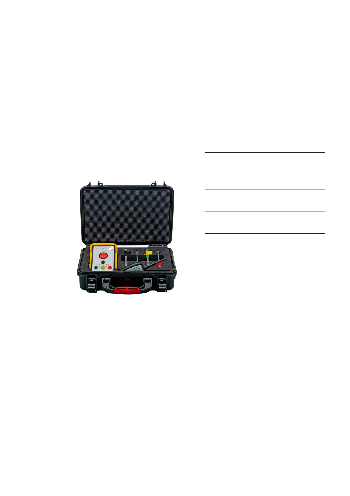
• The ArcSwitch® meter is a portable meter and is
not intended or implied to be handheld when
operating or switching.
• The operator should use great care when
connecting the leads if voltage is present.
• Unused output jacks may present a shock injury
or personal risk. An operator should not place
their fingers over unused outputs as a shock
hazard could be present.
• The operator should not connect the ArcSwitch®
meter in reverse and switch, as this may
damage the ArcSwitch® meter. Current flow is
intended to flow from the common jack to
either output jack.
• DO NOT WORK ALONE.
• The operator should beware when switching
racking or withdrawing a circuit breaker; they
should still be wearing arc flash protection
P.P.E. in accordance with employer or country,
and/or state regulations.

7INTERNATIONAL SYMBOLS 7
—
International symbols
The ArcSwitch® Meter and the ArcSwitch® Panel unit will have the following symbols
on the overlay and on the rear product labels. You should make yourself familiar with
these symbols and this manual before using the ArcSwitch® Meter, ArcSwitch®
Transmitter or ArcSwitch® Panel Unit.
Icon Meaning
AC (Alternating Current)
DC (Direct Current)
ATTENTION! (Warning about a danger, refer to manual)
CAUTION! (Dangerous voltage risk of electric shock, refer to manual)
CLOSE / A CLOSE OR A OUTPUT JACK (Output jack for green output lead)
OPEN / B OPEN OR B OUTPUT JACK (Output jack for red output lead)
BATTERY SYMBOL (Battery powered)
WEEE DIRECTIVE (End of life needs to be recycled responsibly)
CAT III IEC OVERVOLTAGE CATEGORY III (Transient overvoltage protection)
CAT IV IEC OVERVOLTAGE CATEGORY IV (Transient overvoltage protection)
EARTH OR GROUND JACK (Input jack for yellow green input lead)
CONFORMITY MARK (Conforms to EU Directives)
COM COMMON JACK (Input jack for black input lead)
DOUBLE INSULATED (Double Reinforced Insulation)
POWER SWITCH (Controls on / off meter)
MANUAL SYMBOL (Refer to instruction manual)
OPEN CONTACT (Open power contact)
—
International electrical symbols

8ARCSWITCH®MANUAL
ARCSWITCH METER
OPENING
MADE IN IRELAND • PATENT PROTECTED
Caldwell Power & Energy Ltd
ARCSWITCH PANEL
SHOULD BE CARRIED OUT BY A
QUALIFIED ELECTRICIAN
MADE IN IRELAND
Caldwell Power & Energy Ltd

ARCSWITCH PANEL UNIT 9
—
ArcSwitch panel unit
The ArcSwitch® panel unit, can be retrofitted to medium or low voltage switchgear
very easily. It can be commissioned very quickly during a maintenance schedule
without adding extra time to the outage period.
The ArcSwitch® panel Unit, is designed so the
operator can connect the ArcSwitch® meter with
ease, and switch with no tools or switchgear
Electrician has to do is magnetically clip the
the test leads following the colour codes, starting
with the ground first, then the outputs and finally
the com input.
The Electrician is then ready to close or open the
circuit breaker, when they are ready to switch
with the ArcSwitch® meter, all personnel should
be removed to a safe distance, and a final sweep
should be done when switching is ready to take
place.
switching with the ArcSwitch® meter, the greater
the distance you have between you and the circuit
breaker you are switching the safer you are. A
defined minimum distance should be agreed by
specific arc flash study and switching procedure,
this will be different for every site.
The Electrician can then arm the ArcSwitch®
meter, by pressing the master on/off button and
once at a safe distance can then switch safely
with the ArcSwitch® Transmitter.
—
Connecting ArcSwitch®
meter to ArcSwitch®
Panel unit
—

10 ARCSWITCH®MANUAL
—
Meter layout
—
ArcSwitch® meter kit
—
Carry case
ArcSwitch® meter
Protective jacket
Custom foam inlay
User manual
ArcSwitch® Transmitter
Magnetic Hanger
The test leads and connectors provided with in
this kit, conform to IEC 61010 – 031: 2015. and
offer the operator a level of protection in
accordance to CE standards. Only test leads and
connections provided in this kit should be used,
and you should use them only as instructed by the
manufacturer, DO NOT USE test leads or
connectors that are not provided with this kit.
The ArcSwitch® meter kit, will come with the
following items listed in (fig 2.) On receipt of your
kit, you should confirm that all parts are present.

TESTING 11
—
Testing
To test the Close and Open contact
of the ArcSwitch® meter
—
Contact continuity test
ArcSwitch® meter
NOTE: You should be aware that this test will not
help you find a single welded or damaged contact
as there are two contacts in series to create a
power contact.
You can see how to connect to do this test by
• To test the contact of an ArcSwitch® meter.
• First turn on and set the Multimeter to the
continuity function.
• Then connect the Multimeter to the ArcSwitch®
meter across the common jack and the output
jack.
• You are now ready to test.
• Now you can activate the Transmitter for the
Close contact, this should bell out upon
activation and stop once you deactivate the
Transmitter.
• You have now proven the contact has changed
state and you can repeat this on the other
contact.
If the contacts bell out without activation of the
Transmitter, then the contact may be damaged or
welded closed. In such instances you should not
use the ArcSwitch® meter and the ArcSwitch®
meter you should be replaced.
When you are going to use your ArcSwitch® meter,
it is good practice for you to check the contacts
before use, so you know that the ArcSwitch®
meter is functioning correctly and is not
damaged.
Connect your Multimeter up to the ArcSwitch™
and Beep test the contacts to check for contact
operation and welded contacts before use.
—

12 ARCSWITCH®MANUAL
—
Using ArcSwitch meter
The ArcSwitch® meter and transmitter comes
paired together in the manufacturing process
with test leads and connections that are
manufactured in accordance with IEC
Which offer protection to the operator that
should not be reduced. DO NOT USE any other
leads or connectors other than what was
specified and supplied with the ArcSwitch®
meter.
Before use you should Inspect the ArcSwitch®
meter, transmitter, test leads and connectors for
damage. You should also check the outer coating
To turn the ArcSwitch® meter on, press the on
button and the green LED will come on. To turn
off the ArcSwitch® meter, hold the off button till
the green LED goes off.
Before connecting up the ArcSwitch meter® do
not connect the ArcSwitch® meter up and bypass
safety critical interlocks.
How to connect up the ArcSwitch® meter
• The operator should always use best practice
and test the ArcSwitch® meter is working
correctly before use.
• Place the ArcSwitch® meter in the upright
vertical position and magnetically hang it on the
switchgear, while having the ArcSwitch®
Transmitter in your possession.
• Connect the ArcSwitch® meter to the
ArcSwitch® panel Unit to prevent operator error.
• Make sure the ArcSwitch® meter is switched off.
• Take the green and yellow lead and connect
from the ArcSwitch® meter ground jack and
connect it to the ground jack of the ArcSwitch®
panel unit.
• Take the green lead and connect from the
ArcSwitch® meter green output jack and
connect it to the green jack of the ArcSwitch®
panel unit.
• Take the red lead and connect from the
ArcSwitch® meter red output jack and connect
it to the red jack of the ArcSwitch® panel unit.
• Take the black lead and connect from the
ArcSwitch® meter black com jack and connect it
to the black jack of the ArcSwitch® panel unit.
• When all the colours of the test leads and jacks
are correct you are now ready to switch,
• Arm the ArcSwitch® meter by turning it on and
clear the area of personnel,
• you can now switch with the ArcSwitch®
Transmitter from a safe distance.
if you not using the ArcSwitch® panel unit and
connecting straight to terminals and if voltage is
present and the supply cannot be isolated, the
operator should use protective insulating gloves
when connecting or disconnecting.

ELECTRICAL SPECIFICATION 13
—
Electrical specification
ArcSwitch® meter
Power contact
Power contact material Silver Alloy
Mechanical life
Electrical life
Operating voltage
Frequency
Overvoltage protection (III)
Overvoltage protection (IV)
Current
Fuse type
Surge protection
Contacts Normally Open
Contact protection R.C. Snubber Protection
Contact protection Magnetic Arc Quenching
Contact sequence
Contact load type Resistive Loads / Inductive Loads*
ArcSwitch® panel unit
Working voltage
Current
Frequency
Safety
EMC
RoHS.
*NOTE: The opening and closing coils should be in a healthy and operational state.

14 ARCSWITCH®MANUAL
—
Maintenance
The ArcSwitch® meter should be cleaned with a
damp cloth only.
The ArcSwitch® meter is to be used indoors! if it
gets wet, dry it off immediately. DO NOT USE IT
until it is fully dry! if the meter is fully immersed in
water, it should not be used and should be
replaced.
The ArcSwitch® meter should be stored in normal
damage and shorten the life of the electronics.
Use only new batteries on the ArcSwitch® meter.
Low battery power will make the contacts not
work and the meter will not work correctly or may
not operate at all.
Customers are not permitted to modify,
disassemble or repair the ArcSwitch® meter.
Doing so may cause fire, electric shock, or injury,
and will void the warranty.
If the Fuse is blown, disconnect the leads before
opening the cover. DO NOT OPEN the meter if the
leads are connected.
replaced with a higher current rated fuse. If you
need a replacement fuse, please contact us
directly to purchase a replacement fuse.
Replacing the fuse on the ArcSwitch® meter
• Make sure the ArcSwitch® meter is switched off
and it is not connected to a circuit.
• If the test leads are connected remove them
from the ArcSwitch® meter.
• Remove the silicon outer protective boot.
• Turn the ArcSwitch® meter over and remove the
holding on the back cover.
• Remove the back cover. And you should see the
fuse mounted on the printed circuit board.
Remove the defective fuse with an appropriate
fuse puller.
• If the fuse is blown, please eliminate the cause
of this before replacing.
•
rating recommended by the manufacturer.
• DO NOT REPLACE WITH A HIGHER RATED,
UNAPPROVED OR MAKESHIFT FUSE.
• Replace the covers and turn the ArcSwitch®
meter on. Test that the contacts are changing
state and working correctly.
Replacing the battery on the ArcSwitch® meter
see (fig 4.)
• Make sure the ArcSwitch® meter is switched off
and it is not connected to a circuit.
• If the leads are connected, remove them from
the ArcSwitch® meter.
• Remove the silicon outer protective boot.
• Turn the ArcSwitch® meter over and remove the
battery door.
• Remove the battery from the mini snap
connection and replace with a new battery.
• Replace the battery door.
• Replace the silicon outer protective boot.
• Turn the ArcSwitch® meter on and test the
contacts are opening and closing.
—
Replacing the 9V battery
in the ArcSwitch® Meter
—

MAINTENANCE 15
Replacing the battery on the ArcSwitch®
transmitter
• Upon activation of transmitter button and the
battery LED flashes you should replace the
batteries.
• Make sure the ArcSwitch® meter is switched off
and it is not connected to a circuit.
• Turn the ArcSwitch® Transmitter over and
cover see (fig 5.)
• Then remove 2 black screws and lift off battery
door.
•
batteries of the same make and pay attention to
the polarity and that the cables do not get
damaged.
• Replace the battery door and tighten the 2 black
screws.
•
do not get pinched by the back cover.
• Turn the ArcSwitch® meter on and test the
contacts are opening and closing when
commanded by the ArcSwitch® Transmitter.
• If you are storing the ArcSwitch® meter for an
batteries to prevent damage due to possible
leaking of the electrolyte on to the electronic
components inside.
—
Replacing the battery
in the ArcSwitch®
Transmitter
—

16 ARCSWITCH®MANUAL
—
ArcSwitch basic
connection drawing
—
Quick start guide (installation notes)
Rules for the correct installation of the
ArcSwitch panel unit™
In order to guarantee the correct and reliable
operation of the ArcSwitch Panel unit™, the
installation should be carried out by a qualified
electrician and they should follow the
instructions supplied in this document.
Safety requirements
ATTENTION:
Read the manual carefully before starting to use.
and Keep the instructions for future reference.
Do not open the device, touching any internal
components can cause electric shock. Contact
reduce the risk of electric shock, do not dismantle
the back of the device for any reason there is no
service usable parts inside. Moreover, opening
will void the warranty.
Before connecting the device to the power
supply, make sure that all the connections are
correct. Always disconnect the unit from the
supply before any cabling modification.
Any work on the equipment must be
entrusted to a qualified Electrician.
Failure to comply with these instructions can
cause damages, fires or electric shock, and
possible serious injuries or death!
Power supply:
sure the power cable is not damaged, knotted, or
pinched. Do not tamper with the power cable.
Never disconnect the unit by pulling the cable,
avoid touching the pins. Do not carry out any
connecting / disconnecting with wet hands. To
disconnect the device, do not use objects such as
levers. Immediately disconnect the device if you
service.
USE SHOULD BE RESERVED TO QUALIFIED
PERSONNEL ONLY:
The purchased goods are a sophisticated
electronic device that is totally unsuitable to be
must be carried out by a specialist Engineer or
Qualified Electrician.
CB opening circuit CB closing circuit
Closing button
ArcSwitch
panel meter
Closing coil
DC positive
DC negative
Ground / earth
Opening button
Opening coil
Protection trip
—

QUICK START GUIDE (INSTALLATION NOTES) 17
Location
Install of The ArcSwitch Panel Unit ™ indoors, in a
place protected from water splashes and sun
the parameters stated in this manual. Position on
a stable surface, far from any possible vibrations.
Position the ArcSwitch Panel Unit™ so it can be
reached by an operator without the use of a
ladder.
Repairs
Do not open the ArcSwitch Panel Unit™ For any
fault, there is no service usable parts inside. The
opening of the ArcSwitch Panel Unit™ and or the
removal of the warranty label entails the
automatic forfeiture of the warranty. The
Warranty seal is applied to all devices.
Fitting the panel unit
The ArcSwitch Panel Unit™ must be fitted on a LV
control panel and is designed for indoor use
only and it should be fitted by a Qualified
Electrician complying with the following
Rear electrical connections
The Connections on the rear of the ArcSwitch
Panel Unit™
• Common terminal is connected to the DC
Positive Feed.
• Ground terminal is connected to Ground /
Earth.
• Close terminal is connected to the switched
side of the closing button.
• Open terminal is connected to the switched
side of the opening button.
Polarity needs to be observed because you are
switching the dc positive through the Portable
ArcSwitch Meter™ to the opening and closing
coils.
Front electrical connections
The Connections on the front of the ArcSwitch
Panel Unit™
• COM is connected to the COM on the Portable
ArcSwitch Meter™
• Ground is connected to Ground on the Portable
ArcSwitch Meter™
• Close output is connected to Close output on
the Portable ArcSwitch Meter™
• Open output is connected to the Open output
on the Portable ArcSwitch Meter™
All connections on the front of the ArcSwitch
panel Unit™ to the Portable ArcSwitch Meter™
should be made by the leads provided in the
Portable ArcSwitch Meter kit™
when retrofitting.
If you are cutting metal beware of metal swarf
and clean as you go.
Fit the ArcSwitch Panel Unit™ into the cutout and
secure with the blocks supplied.
You can connect ArcSwitch Panel Unit™ by
paralleled across the open and close buttons
Wire up the rear terminals as follows
• Ground, To the ground / Earth on door
•
• Switched wire to the Close terminal
• Switched wire to the Open terminal
When wiring up the ArcSwitch Panel Unit™ DO
NOT wire it in a fashion where electrical control
interlocks are bypassed as this could cause injury
or death.
—
—
—
Panel mounting
ArcSwitch Panel Unit
—
ArcSwitch Panel Unit
rear electrical connector

18 ARCSWITCH®MANUAL
• The ArcSwitch Panel Unit™ enclosure should be
secure and tight in the panel.
• The Electrical connections are tight and
secured at the back of the ArcSwitch Meter™.
• The Plug is tight and secured to the rear socket.
• The DC Control Voltage is present at the front
Com socket and Positive Polarity is correct.
• You can now connect the ArcSwitch Meter™ to
the front input jacks and test open close
operations of the main circuit breaker.
You have now Commissioned the remote opening
and closing of your circuit breaker.
Operating
Should only be carried out by a Qualified
Electrician.
The operation of ArcSwitch Panel Unit™
and the ArcSwitch Meter™ operates by
switching the dc positive through a
closing coil and opening coil fitted
internally of the circuit breaker via a
control ArcSwitch Transmitter.
Note: the input jacks colours and test leads
colours should be obsereved.
Installation rules:
Every ArcSwitch Panel Unit ™ must be connected
with wire cabling having a minimum section of
Installation
Should only be carried out by a Qualified
Electrician.
—
When installing the ArcSwitch Panel Unit™ the
control voltages in the low voltage compartment
system should be in place before work should
commence to prevent accidental shock or
electrocution when installing.
Retrofitting
Should only be carried out by a Qualified
Electrician.
The advantage with the ArcSwitch Panel Unit™ is
you can install it during a maintenance outage
period, without increasing the time period
needed for your maintenance outage providing
the installation has been planned accordingly.
Commissioning
Should only be carried out by a Qualified
Electrician.
To Commission the ArcSwitch Panel Unit™ you
should check for the following bullet Points as a
minimum.
The ArcSwitch Panel Unit™ is paralleled off the
opening and closing button on the front door of
the LV Control compartment. When operating via
ArcSwitch Transmitter the operator should put
they are switching.
Commissioning of the remote opening and
closing of the system is the sole responsibility of
the system electrical engineer and no
responsibility is implied or taken by the
manufacturer.
—
ArcSwitch Panel
Unit front electrical
connections

WARRANTY 19
—
Warranty
Limited warranty and limitiation of liability
The ArcSwitch® Meter is warranted to the original
purchaser against defects in material and
purchase. This warranty does not cover fuses,
disposable batteries or damage from accident,
neglect misuse, alteration, contamination or
switching unrated loads, abnormal conditions of
operation or failures caused by negligent, or
normal wear and tear of mechanical components.
This warranty covers the original purchaser only
and is not transferable. Resellers are not
behalf of Arcswitch®
This warranty is your only remedy. No other
warranties, such as fitness for a particular
liable for any indirect, incidental or consequential
damages or losses, arising from any theory or
cause.
The manufacturer shall not be liable for loss of
use of the instrument or other incidental or
loss, or for any claim or claims for such damage,
countries laws vary, so the above limitations or

20 ARCSWITCH®MANUAL
—
Repair and calibration
For warranty repair during the warranty period,
contact the place of purchase and obtain
authorization information, arrange to return the
product with proof of purchase to the place of
purchase or an authorized service centre or
the following should be accompanied your name,
company name, address, telephone number and
service required.
Additionally, please include a brief description of
the problem or service requested and include the
full test kit, with leads, connectors, and
repair or replacement charges will apply. Before
sending for repair please check your batteries.
The ArcSwitch® meter should not be opened or
repaired as there is no internal serviceable parts
BATTERY) see maintenance section above on how
to replace the fuse and the battery.
Table of contents
Other ABB Construction Equipment manuals