abco STR1800 LPG User manual

!
19.02.2019
Operating manual
GB
STR1800 LPG

3
Contents
1 Introduction/Usage conformant with intended purpose.3
2 Safety instructions.............................................................3
2.1 General safety instructions......................................3
2.2 General safety instructions......................................4
2.3 Symbols in the operating manual……………………….5
2.4 Protective devices........................................................5
3 Environmental protection....................................................5
4Device description…………………………….................................5
4.1 Function...............................................................................5
4.2 Technical specifications................................................6
4.3 Control and functional elements................................6
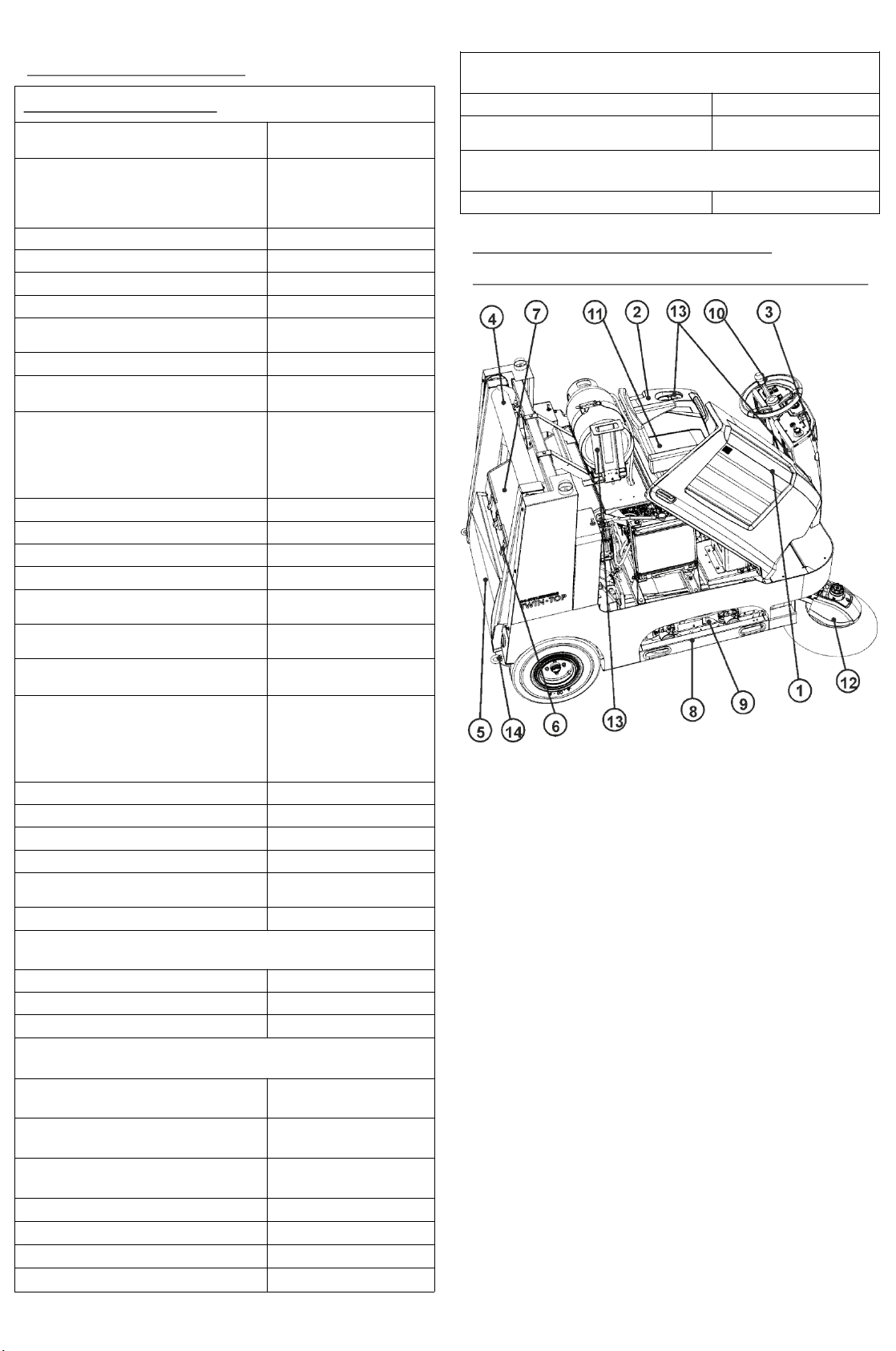
4.3.1 Overview of control and functional elements……6
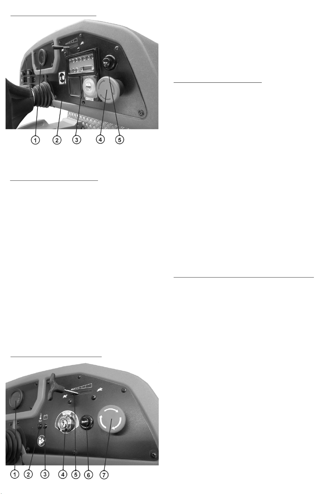
4.3.2 control panel diesel…………..………..……………………7
4.3.3 control panel unit diesel…...….…..……………………7
4.3.4 control panel LPG…………..….………….………………….…7
4.3.5 control panel petrol……….…………….………………………7
4.3.6 control panel left hand…....…………..………………………7
4.4 Unloading the machine..................................................9
4.5 Initial operation..........................................................9
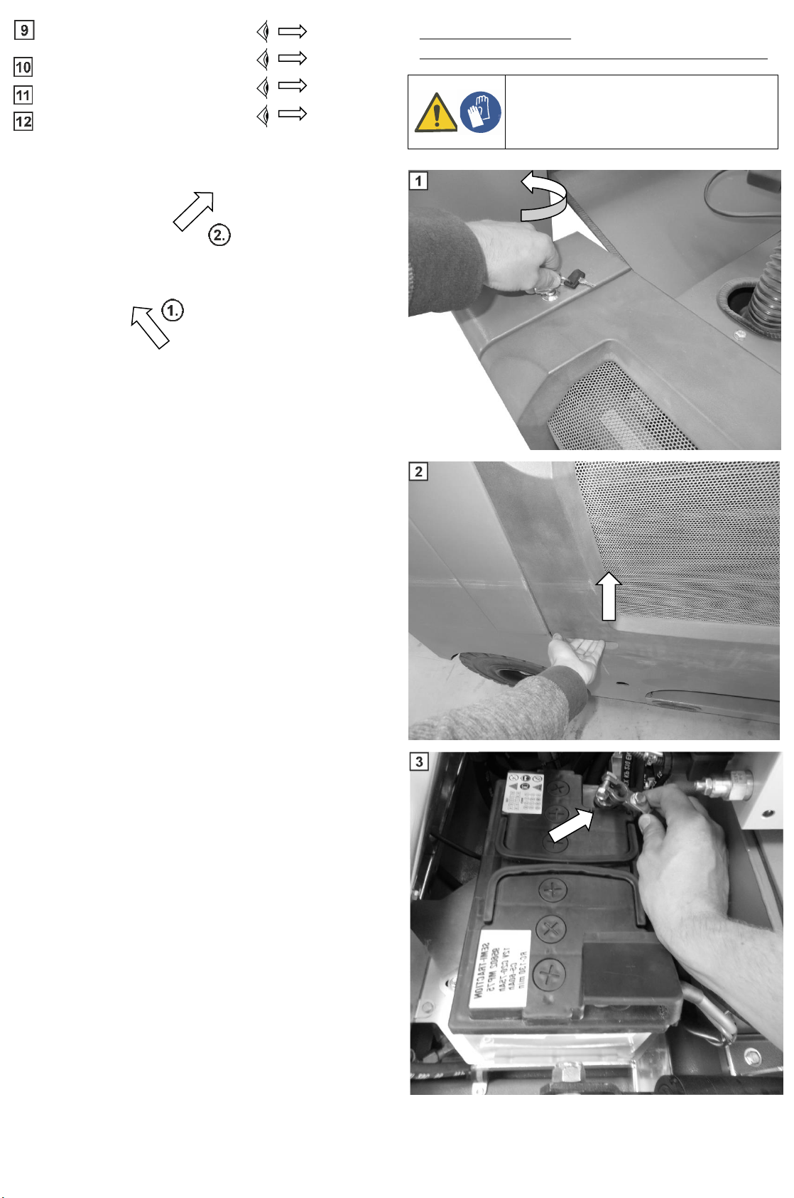
4.5.1 Establishing the machine-battery connection……9
4.5.2 Fuel fill............................................................................10
4.5.3 Gas cylinder assembly................................................10
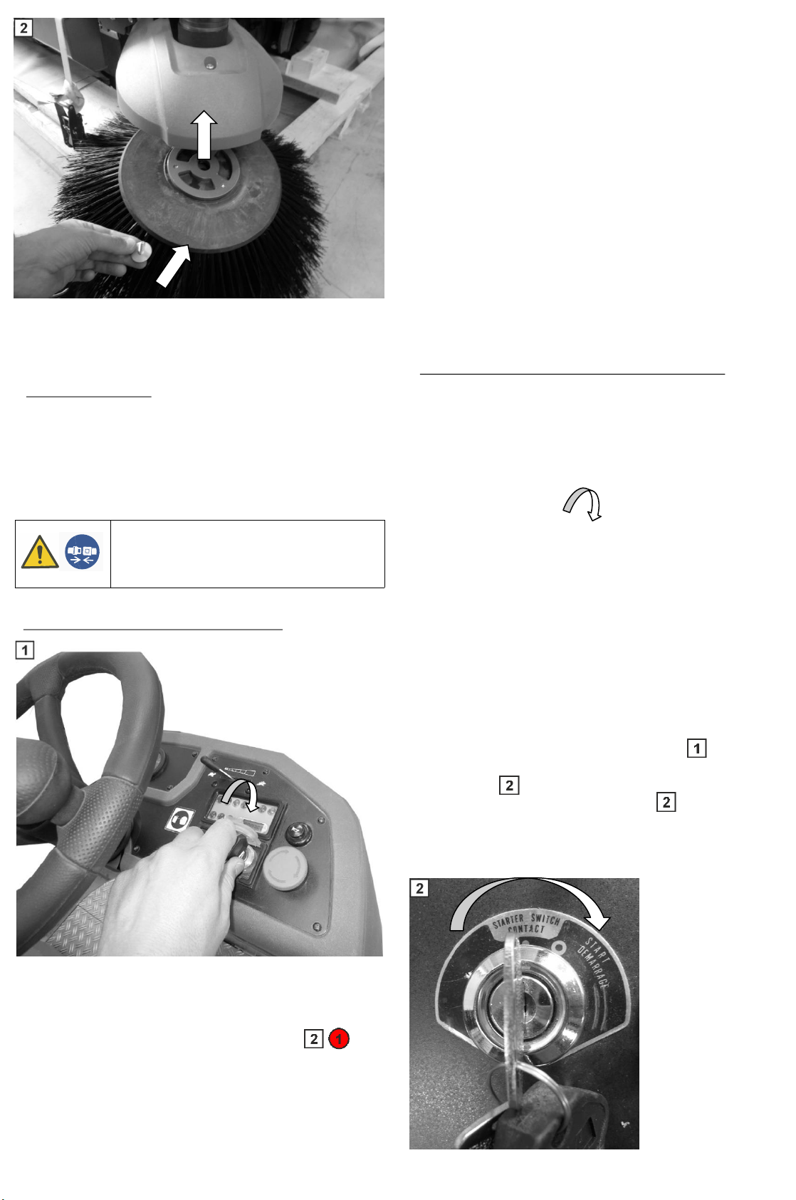
4.5.4 Mounting the side brush......................................10
5 Operation …………….…………………………………………..………..11
5.1 Drive system……………………......................................11
5.1.1 Starting the sweeper unit diesel.......................11
5.1.2 Starting the sweep LPG/diesel version…….……...11
5.1.2 Drive Modus ………………………………………………………12
5.1.3 Parking the sweeper....................................12
5.2 Sweeping system ……………………..………………….....13
5.2.1 Sweeping wet materials …..………………………….13
5.2.2 Height adjustment of the sweeping roller….....13
5.2.3 Operation of the sweeper roller drive…….………13
5.2.4 Dismantling of the Sweeper rollers ………….……14
5.2.5 Installation of the Sweeper rollers …….…..……16
5.2.6 Height adjustment of the side brush..…………….16
5.2.7 Operation of the side brush drive………………….17
5.2.8 Dismantling the side brush……………….………………17
5.2.9 Installation of the side brush……………………………18
5.3 Dust suction……………………………………….………….…….18
5.3.1 Operation of the fan ………..……….………………….18
5.3.2 Operation of the Filter vibrator ………….……………18
5.3.3 Dismantling the filter……..…………………………………18
5.3.4 Installation of the filter……..……...………………………19
5.3.5 Filter cleaning….………………………………………………20
5.4 High-dumping system …………………..………………..…..20
5.4.1 Operation of the high-dumping system .…………20
5.4.1 Cleaning the refuse container ……………..………21
5.4.2 Maintenance support….…………………..…………………21
5.5 Fuse box…………………….…………………………….……………22
6 Cleaning and maintenance……….........................………………22
6.1 Safety instructions for cleaning and maintenance…..22
6.2 General cleaning and maintenance instructions…22
7 Faults, fault indications and remedy……………………24
8 Maintenance intervals ……………………………………………25
8.1 daily maintenance instructions……………………..…25
8.2 Additionally every 50 operating hours ……………...25
8.3 Additionally every 100 operating hours………..…...25
9 Nameplate………………………………………….…………….……………25
10 Accessories and spare parts ………………………....…………….25
11 Warranty …………………………………………….……………….………25
12 Transport of the sweeper …………..…….……………….………26
13 EC Declaration of Conformity ……………..……….………..…27
Introduction/Intended use
1
This operating manual contain instructions for using the sweeper.
Our products are subject to continuous improvement. Therefore,
design changes that were made after this manual went to print could
not be incorporated.
If you have any questions, please contact our Service department.
The operating manual must be read and applied by all persons who
operate the sweeper.
Apart from the operating manual and the regulations for accident
prevention applicable in the country of use and the location of use, the
common, recognised rules for safe and technically correct
working must also be followed.
The appliance is intended exclusively for sweeping on solid surfaces
(for example.: parking areas, walkways, shop floors).
The area to be swept should not be wet.
The sweeper may only be used by reliable and instructed personnel.
Prevent use by children, teenagers and other unauthorized persons,
e.g. by removing the key after use.
Any other or additional use is considered to be improper (see. safety
instructions Ch. ). The manufacturer shall not be liable for resulting
damages.
The operator is solely responsible for the risk.
Intended use also includes compliance with the operating manual, the
safety instructions and the inspection and maintenance requirements.
Only drive on routes and places that have been expressly assigned.
Notes on appropriate surfaces (asphalt, screed, industrial flooring,
concrete, paving stones, carpets, artificial grass, etc.)
Safety instructions
2
2.1 General safety instructions
•Only use the machine in perfect condition and as
intended, while being aware of safety and dangers, and in
compliance with this operating manual!
•The machine does not have road use homologation.
•In addition to the operating manual, also note the
generally applicable statutory and other binding
regulations relating to accident prevention and
environmental protection!
•It is forbidden to sweep flammable, toxic or explosive
substances, as well as flammable gases or undiluted
acids and solvents, burning or smouldering objects!

READ THE OPERATING MANUAL!
WARNING: HOT SURFACES!
WARNING: RISK OF HAND INJURIES!
4
•The device is not suitable for holding liquids, ropes,
twine, wire or the like.
•Use the machine exclusively with the hopper inserted, to
prevent injuries from flying parts.
•The transport of loads with the sweeper is not
permissible.
•Faults, in particular those that may impair safety, must be
remedied immediately!
•Do not perform any modifications, additions or
conversions on the machine without approval from the
manufacturer.
•Spare parts must meet the requirements defined by the
manufacturer. This is always guaranteed with original
spare parts.
•Accessories and spare parts may only be installed by an
authorized service centre.
•Ensure a safe and environmentally friendly disposal of
operating and auxiliary materials as well as replaced
parts, especially the batteries!
•Suitable, non-slip footwear must be worn to avoid
accidents.
•Persons (including children) who, due to their physical,
sensory or mental abilities or their inexperience or
ignorance, are not able to use the machine safely, may
not use this machine without supervision or instruction
by a responsible person! Children should be supervised
to ensure they do not play with the machine.
•Caution: Loose clothing may be drawn-in by rotating
parts.
•The operating instructions of the battery manufacturer
for his product, as well as the specifications of the
legislator for the handling of rechargeable batteries
must be observed!
•Please observe the fact that the accumulators are filled
with battery acid!
•Always keep the batteries clean and dry, in order to
prevent leakage currents! Never short-circuit the battery
terminals!
•If you need to charge the battery, only charge it in well-
ventilated rooms and using a charger that is approved by
the manufacturer. Keep it away from naked flames and
electrical sparks.
•Smoking, eating and drinking must be avoided in the
area around the battery charging station must be
avoided to prevent damage to health.
•Observe the maximum gradient and maximum possible
oblique inclination specified in the technical data when
driving along a slope Abrupt or excessive steering,
especially on slopes, may cause the machine to tip over.
Adapt your driving style and speed to the circumstances.
•Never reach under the machine while it is running
(danger of entanglement).
•In areas which are susceptible to dust, always switch on
the dust extractor, shake regularly and wear a breathing
mask.
•Always disconnect the battery when carrying out
maintenance work or replacing components. Wear a face
mask and gloves while you are doing this and ensure
that the machine cannot roll away (chocks).
•Do not use the machine in the rain and do not clean it
with (a) water (jet).
•When the machine is parked (especially on slopes), it
must be secured with the chocks.
•In the event of a fault message (red indicator light comes
on), switch off the machine immediately and diagnose
the fault.
•Ensure that sufficient breaks are taken during use.
•The interior of the machine must only be accessible to
trained specialist personnel. This is ensured by a
separate key. This may only be given to personnel who
have received training in this.
•The machine may never be used without dust filters or
other attachments.
2.2 Symbols on the device

5
Environmental protection.
3
Recycling of packaging materials. Do not dispose packaging
materials in the household rubbish and recycle it instead.
Used devices contain valuable recyclable materials which
should be salvaged for recycling. Batteries, oil and similar
substances may not be released into the environment.
Please dispose used devices in suitable collection systems.
Device description
4
The TT1800 is a sweeper with a fully hydraulic drive system
driven by a combustion engine, which is equipped with the
tandem roller sweeping system. It is equipped with an
automatically lowering sweeping roller and a powerful dust
extractor.
In the TRS-Flex system, the sweeping rollers adapt to the
unevenness of the ground. The dirt is first transported by
the side brushes (1) from the corners and edges of the
sweeping area to the centre of the machine and thus to the
two sweeping rollers (2) rotating against each other. The
dirt is picked up by them and transported to the refuse
container (3) behind them. The dust that is whirled up by the
sweeping process is sucked in by two fans (4), filtered
through a flat-pleated filter (5) and thereby separated from
the clean air. A cleaning system (6) releases the dust cake
adhering to the lamella filter and drops it into the refuse
container. The refuse container is emptied with the high-
dumping system (7).
4.1 Function
2.4 Safety Devices
The tipping function of the dust container can only be
operated if the dust container is almost extended.
The high-dumping system must be fixed by a mechanical
support during maintenance work when the high-dumping
system is extended.
All protective devices of the machine must not be bridged
or put out of service!
2.3 Symbols in the operating manual
WARNING! ATTENTION! DO NOT TRANSPORT
BY FORKLIFTTRUCK!
WARNING! ATTENTION! DANGER!
THE DESCRIBED INSTRUCTIONS MUST BE
OBSERVED!
WARNING: RISK OF HAND INJURIES!
WARNING: POTENTIALLY FLAMMABLE
SUBSTANCES!
WARNING: ELECTRICAL VOLTAGE!
WARNING: HOT SURFACES!
WARNING: GAS CYLINDERS!
WEAR PROTECTIVE GOGGLES!
USE A RETENTION SYSTEM
WEAR PROTECTIVE GOGGLES!
USE PROTECTIVE FOOTWEAR
WEAR GLOVES
The sweeper can only be started if...
a) the operator is seated in the driver's seat.
b) the start key is turned clockwise.
c) the emergency stop switch is not operated.

6
DEVICE SPECIFICATIONS
Model: TT1800D
Combustion engine Kohler KDW1003
3-Cylinder
water-cooled 19,5KW/
26,1PS 3600U/Min
Length / Width / Height [mm]
2095/1145/1520
Net weight [kg] 1110
Transport weight [kg] 1205
Permissible total weight [kg] 1600
consumption
(Information manufacturer) [l/h] 4,3
Runtime (calculated) [h] 2,3
Modell: TT1800LPG
Combustion engine Kubota DF752
3-Cylinder water-
cooled
17,5KW/ 23,8PS
3600U/Min
Length / Width / Height [mm] 2095/1145/1555
Net weight [kg] 1035
Transport weight [kg] 1130
Permissible total weight [kg] 1600
Consumption
(Information manufacturer) [kg/h] 3,89
Runtime
(calculated 11kg-gas cylinder)[h] 2,8
Modell: TT1800
petrol
Combustion engine Kohler ELH 775
2-V-Cylinder
water-cooled
22,4KW/ 30PS
3600U/Min
Length / Width / Height [mm]
2095/1145/1520
Net weight [kg] 1050
Transport weight [kg] 1145
Permissible total weight [kg] 1600
consumption
(Information manufacturer) [l/h] 4,8
Runtime (calculated) [h] 2,08
DRIVING CHARACTERISTICS
Speed [km/h] 10
Turning radius [m] 1,55
Max. gradient. [%] 20
SWEEPING PROPERTIES TRS
-Flex-System
Sweeping width
without sidebrush [mm]
1000
Sweeping width with
1 side brush[mm] 1400
Sweeping width with
2 side brushes [mm]
1800
Hopper volume [l]
380
Filter type [-]
Flat-fold filter
Filter area [m²] 8,8
Net cleaning surface [m²]
125.000
4.2 Technical specifications
ELECTRICAL PROPERTIES
Total current consumption [V]
12
Battery [-] Battery Eternity 12V
75Ah (C20) acid
Emissionen
Sound pressure level LWA[dB] 100
4.3 Control and functional elements
1 Fuse box
2 Brake pedal
3 Parking brake
4 Reverse pedal
5 Forward pedal
1 Right side fairing 8 Fender
2 Left side fairing 9 Sweep roller system
3 Front fairing 10 Steering wheel
4 High-dumping system 11 Driver's seat
5 Dust container 12 Side brush
6 Rain flap locks 13 Gas cylinder holder
and filter box cover (LPG version)
7 Filter system 14 Towing lugs
4.3.1 Overview of control and functional elements

7
1 Elapsed-hour meter
2 Coolant temperature indicator light
3 Generator indicator light (charge voltage)
4 Ignition switch
5 Gas lever
6 Horn
7 Emergency stop switch
1 Level indicator 4 Emergency stop switch
2 Gas lever 5 Horn
3 Control panel unit diesel
4.3.2 Control panel unit diesel
1 Elapsed-hour meter
2 Level indicator
3 Generator indicator light (charge voltage)
4 Ignition switch
5 Gas lever
6 Horn
7 Emergency stop switch
4.3.5 Control panel unit petrol
4.3.4 Control panel LPG version
Note: Some indicator lamps not working
1 Preheating indicator lamp 6 Warning lamp
2 Warning lamp 7 Obstruction indicator lamp
3 Oil overheating Air filter
4 Elapsed-hour meter 8 Ignition switch
5 Oil pressure indicator lamp
4.3.3 Control panel unit diesel
4.3.6 Control panel left side (all engine versions)
1 Sweeping roller ON/OFF 6 Retract high-dumping system
2 Side brush ON/OFF 7 Retract dust container
3 Vibrator ON 8 Extend high-dumping system
4 Fan ON 9 Tip out dust container
5 Front light ON/OFF

8
4.4 Unloading the machine
WARNING! - The sweeper must not be unloaded
from the pallet using a forklift truck! This will
result in damage to the machine! This increases
the risk of injury from tipping loads! Drive
carefully down the ramp. Damage to the machine
can be avoided by a 2nd person.

WARNING! –Wear protective gloves when
working around the battery to avoid injury.
9
4.5 Initial operation
4.5.1 Establishing the machine-battery connection
Fuel fill
Page 10 ; 4.5.3
Gas cylinder assembly
Page 9; 4.5.1
Establishing the machine-battery
connection Page 10; 4.5.2
Page 10; 4.5.4
Mounting the side brush

10
4.5.2 Fuel fill
4.5.4 Attaching the side brushes
4.5.3 Gas cylinder assembly
WARNUNG! –Caution: flammable substances.
Wear protective gloves, a face mark and
goggles when filling. Only fill the fuels
specified for your engine version.
WARNING! –The gas cylinder may only be
connected by qualified personnel! Take care
when using the assembly aid. There is a risk
of hand injuries if the device is not handled
properly.
-: Attach the gas cylinder and fasten with a lashing
strap. Ensure that the assembly aid engages securely. Ensure
that the gas hoses are not damaged. This is an explanation
for the deluxe version. In the standard version, the gas
cylinder must be securely mounted on the holder.
Movement ( - ) is not possible here.
: Remove the cable tie and watch for loose parts.

Before starting, open the shut-off valve on the gas
cylinder (LPG version only) and check all fluid
levels. Insert the key into the ignition switch ( ).
to start the engine. Turn the key clockwise to
position "0" ( ) to switch on the ignition. Turn
the ignition key further towards "Start" ( ). to
start the engine. After starting, release this. Do not
press the drive pedals.
Check all fluid levels before starting. Insert the key into the
ignition switch to start the engine. Turn the key clockwise
until it audibly engages. The signal lamps of the control panel
light up now. The "preheating" indicator lamp ( )
means that the engine combustion chamber is preheated to
ensure a smooth start. Please wait until the indicator lamp
goes off. Once it goes off, you can start the engine by turning
the key further clockwise. Do not press the drive pedals. After
starting, release the ignition key.
11
Operation
5
5.1 Drive system
Your sweeper is equipped with a combustion engine. We
recommend using the machine only in well-ventilated
rooms. The combustion engines must be retracted during
initial commissioning. The power consumption in the first
50 hours in service must not exceed 70% of the full load
power.
5.1.1 Starting the machine unit diesel
5.1.2 Starting the sweep LPG/Petrol version
ATTENTION! –Seat belts must always be
used during operation.

12
5.1.2 Drive System
The machine advances by pressing the right-hand drive
pedal.
The machine reverses by pressing the left-hand drive pedal.
Ensure that the parking brake is released. Do not apply the
brake while driving.
5.1.3 Parking the sweeper
Park the machine on dry and level ground (without slope).
Apply the parking brake ( ). ).
Secure the machine additionally with chocks ( - ).
They can be found inside the machine.
Regulate the rpm of the engine by using the throttle lever.

13
After parking the machine, remove the ignition key and lock
the side doors with the workshop key to prevent
unauthorised access. ( - ).
5.2 Sweeping system
5.2.1 Sweeping wet materials
ATTENTION! –Switch off the fan when
sweeping wet refuse.
This possibly will cause damage to the the
dust filter!
5.2.2 Height adjustment of the sweeping rollers
Your sweeper is equipped with the Tandem Roller Flex
System (TRS-Flex) and automatic lowering of the sweeping
roller. The sweeping rollers adapt to the ground, which
means there is no need for height adjustment. Nevertheless,
this may become necessary if the rollers are worn or
adjusted to a certain maximum sweeping pattern. Lift up the
left side door first. You can raise or lower the max. low point
by turning the adjusting screw ( ). Only adjust this when
the machine is switched off.
5.2.3 Operation of the sweeper roller drive
Press the switch to set the sweeping rollers to position I.
The sweeping rollers can be operated separately from the
operation of the side brush. The engine must be running for
operation.
ATTENTION! –Always wear face masks and
seat belts when sweeping.

14
5.2.4 Dismantling of the Sweeper rollers
2x
ATTENTION! –Always wear gloves, goggles
and a face mask during assembly.
2x

15

16
5.2.5 Installation of the Sweeper rollers
ATTENTION! –Always wear gloves, goggles
and a face mask during assembly. Ensure
that the sweeping rollers are installed in the
correct direction! ( )
The slots of the sweeping roller ( ) must be guided onto
drivers ( ). A torch may be a useful aid here ( ).
After installing the sweeping rollers, carry out the steps in
chapter 5.2.4 in reverse order.
5.2.6 Height adjustment of the side brush
You can adjust the height of the side brush. By loosening
the screw connection ( ) you can adjust the height of the
side brush in several steps using the eccentric. After
adjustment, retighten the screw connection. After loosening
several times, please replace the screw connection.

17
5.2.7 Operation of the side brush drive
Press the switch to set the side brush to position I. The side
brush can be operated separately from the operation of the
sweeping rollers. The side brush retracts automatically
when switched on. The engine must be running for
operation. Turn the switch to the 0 position to switch it off.
ATTENTION! –Always wear a face mask and
seat belt when sweeping.
5.2.8 Dismantling the side brush
ATTENTION! –Wear gloves, goggles and a
face mask during assembly. Loose parts must
be secured.

18
5.2.9 Installation of the side brush
5.3 Dust suction
5.3.1 Operation of the fan
Press the switch to set the fan to position I. The fan remains
active until you press it to the opposite position. Turn the
switch to the 0 position to switch it off. Generally leave the
fan switched on during sweeping. Switch off the fan when
sweeping wet refuse.
Press the switch to position I to activate the vibrator. Turn
the switch to position 0 to switch it off. When the vibrator is
switched on, the dust cake accruing in the filter
(accumulation of dust between the filter pleats) is vibrated
into the refuse container. High filter performance can only
be guaranteed in this way. Depending on the concentration
of dust, we recommend that vibration take place at intervals
of 5 to 10 minutes.
5.3.2 Operation of the filter vibrator
5.3.3 Dismantling the filter
ATTENTION! –Wear a face mask when
removing the filter.
ATTENTION! –Wear gloves, goggles and a
face mask during assembly. Loose parts must
be secured.

19
5.3.4 Installation of the filter
ATTENTION! –Wear a face mask when
removing the filter.
Never expose the filter to moisture. The
filter material can sustain irreparable
damage and adversely affect the air
cleaningproperties of the dust extractor.
Ensure that the filter is installed in the correct direction
( ). Install the filter in reverse order to the steps for its
removal. Before installation, please clean the contact
surfaces of the filter ( ). If it is necessary to adjust the
filter contact pressure, you can adjust it via the screw
connection ( ).
When removing the filter, be careful, do not damage the
gasket from below ( ).

ATTENTION! DANGER! –When working on
the high-dumping system, the refuse
container with high-dumping arms must be
secured against sudden pressure loss in the
hydraulics system (such as a hose rupture)
by the maintenance support
( 20/5.4.3). There is a danger of
body parts being crushed when the high-
dumping system is raised or lowered. A
second person must cordon off the swivel
space. The high-dumping system can be
loaded up to a maximum weight of 250 kg
(in the refuse container).
20
5.3.5 Filter cleaning
ATTENTION! –When cleaning the filter, wear
gloves and a face mask and ensure that the
environment is well ventilated.
5.4 High-dumping system
5.4.1 Operation of the high-dumping system
Press the switch to raise the refuse container ( ). Press
the switch ( ) to lower the refuse container. The engine
must be running for operation. Press the switch ( ) to
empty the refuse container (tipping). Press the switch ( )
to retract the refuse container. The tipping function can
only be used when the refuse container is almost
completely extended.
Clean the filter by tapping it by hand ( ). Then vacuum the
filter ( ). If the dirt cannot be removed or there is damage,
replace the filter. Check that the lower seal is free of damage.
Never clean the filter wet! If necessary, you can blow out the
filter with compressed air from the clean side.

21
5.4.2 Cleaning the refuse container.
Sweep out the refuse container with a hand brush. If there is
any stubborn dirt left in it, soften it with warm water. During
cleaning, please ensure that the area leading to the refuse
container ( ) is clear and cleaned.
5.4.3 Maintenance support
ATTENTION! DANGER! - Risk of crushing
parts of the body. Wear gloves .
Raise the high-dumping system completely. Loosen the mounting
bracket ( ) of the maintenance support and swivel it towards
the lifting cylinder ( ). Now lower the high-dumping system
slowly and guide the maintenance support along the lifting
cylinder tube until the high-dumping system is fixed securely
( ).
ATTENTION! –Only clean the refuse
container while wearing gloves, goggles and
a face mask. Never clean with compressed
air, as particles of dirt which are ejected can
lead to injuries and health impairments.
Table of contents
Popular Floor Machine manuals by other brands

Nilfisk-Advance
Nilfisk-Advance PBU 56384165 Operator's manual

COMAC
COMAC CS80 B Use and maintenance manual

Mitchell
Mitchell BRUMBY Operations Manual and troubleshooting guide

Nilfisk-ALTO
Nilfisk-ALTO SCRUBTEC 343E user manual

lavina
lavina 32-S-E user manual

Minuteman
Minuteman FR17115 OPERATING & SERVICE MANUAL

Edco
Edco TL-9 TURBO-LITE Operator's instruction manual

Tennant
Tennant 1200 Operator and parts manual

Nacecare
Nacecare Numatic TT 516 Owner's instructions

GÜDE
GÜDE KM 7.14 instructions

Nobles
Nobles SpeedGleam Operator and parts manual

Minuteman
Minuteman Lumina 20 Traction Drive Parts and instruction manual