Onfloor OF20SH User manual

2
Table of Contents
General Instructions .............................................................................................................. 3
Silica Vacuum Warning.......................................................................................................... 4
Important Safety Instructions................................................................................................ 5
Electrical Connections............................................................................................................ 6
Operating Instructions........................................................................................................... 7
Installation & Changing of Accessory Tools ............................................................................ 8
Changing and Installation of Attachments........................................................................... 8
Belt Changing Instructions.................................................................................................. 9
Inner Bowl Removal Instructions ...................................................................................... 10
Inner Bowl Bearing Replacement...................................................................................... 11
Pulley Bearing Replacement ............................................................................................. 14
General Safety Precautions.................................................................................................. 17
Machine Maintenance...................................................................................................... 17
OF20SL Handle & Base Assembly Drawing & Parts List ......................................................... 18
OF20SH Handle & Base Assembly Drawing & Parts List ........................................................ 19
OF20SL & SH Outer Bowl Drawing & Parts List ..................................................................... 20
OF20SL & SH Inner Bowl Drawing & Parts List ...................................................................... 21
Troubleshooting Guide ........................................................................................................ 22
Warranty Information ......................................................................................................... 23

3
General Instructions
READ & FOLLOW ALL INSTRUCTIONS BEFORE USING THIS FLOOR
MACHINE
This floor machine will afford you many years of trouble-free operating satisfaction if it is given proper
care. All parts have passed rigid quality control standards before being assembled to produce the
finished product. Prior to packaging, units are again inspected for assurance of flawless operation.
This floor machine was protectively packed to prevent damage in shipment. We recommend that upon
delivery, remove the unit from its carton and carefully inspect it for any possible damage in transit. A
warranty card is affixed to the handle. It is your responsibility to fill it out and send it to our office to
register your purchase andstart yourwarranty. Failure to send us this card in one week upon receipt of the
machine may void the warranty.
If damage is discovered, immediately notify the transportation company that delivered your floor
machine. As a shipper, we are unable to act upon any claim for concealed damage. You must originate any
claim within 5 days of delivery.
These instructions are for your protection and information. PLEASE READ
CAREFUL
L
Y! Failure to
follow these precautions could result in injury or discomfort.
Treat this floor machine as you would any other high-grade precision-made product. Throwing,
dropping, unreasonable bumping across thresholds and other misuse may result in a damaged unit and
invalidate the warranty.
[Thissectionintentionallyleftblank]

4
Silica Vacuum Warning
Grinding/sanding of masonry, concrete, metal and other materials with silica in
their composition may give off dust or mists containing crystalline silica.
Silica is a basic component of sand, quartz, brick, clay, granite and numerous other minerals and rocks.
Repeated and/or substantial inhalation of airborne crystalline silica can cause serious or fatal respiratory
diseases, including silicosis. In addition, California and some other authorities have listed respirable
crystalline silica as a substance known to cause cancer. When grinding such materials, always follow
respiratory precautions. Use appropriate NIOSH-approved respiratory protection and OSHA approved
vacuum where dust hazard may occur.
CALIFORNIA PROPOSITION 65 MESSAGE Some dust created by power sanding, sawing, grinding, drilling,
and other construction activities contain chemicals known (to the State of California) to cause cancer,
birth defects or other reproductive harm. Some examples of these chemicals are: • Lead, from lead-
based paints • Crystalline silica from bricks, cement and other masonry products • Arsenic and
chromium, from chemically treated lumber. For further information, consult the following sources:
http://www.osha.gov/dsg/topics/silicacrystalline/index.html
http://www.cdc.gov/niosh/docs/96-112/
http://oehha.ca.gov/prop65/law/P65law72003.html
http://www.dir.ca.gov/Title8/sub4.html
Your risk from these exposures varies depending on how often you do this type of work. To reduce your
exposure to these chemicals, work in a well-ventilated area, and work with approved safety equipment,
such as dust masks that are specially designed to filter out microscopic particles. The use of a dust
extraction device should always be used when grinding/sanding dry with Onfloor equipment. To achieve
a high level of dust collection, use an industrial HEPA vacuum cleaner.

5
Important Safety Instructions
To reduce the risk of fire, electric shock or injury:
Read all instructions before using this floor machine.
1) DO NOT leave the floor machine plugged in when not in use. Unplug the machine from the
outlet when not in use and/or before servicing.
2) Electric shock could occur if exposed to rain. Store indoors.
3) This is NOT a toy. Close attention is necessary when used around or near children.
4) Use only as described in this manual. Use only manufacturer's recommended attachments.
5) DO NOT use with damaged cord plug. If the floor machine is not working as it should because it
has been dropped, damaged, left outdoors, or dropped into water, contact the manufacturer or
authorized service center.
6) DO NOT handle the plug or operate with wet hands.
7) DO NOT pull or carry by cord, use power cord as a handle, close a door on cord, or pull cord
around sharp edges or corners. DONOT run floor machine over the cord. Keep cord away from
heated surfaces.
8) DO NOT unplug by pulling on cord. To un- plug, grasp plug, not the power cord.
9) DO NOT put any object into motor openings.
10) Keep hair, loose clothing, fingers and all parts of body away from moving parts.
11) DO NOT use a vacuum without the proper manufacturer’s filters in place.
12) DO NOT operate where anesthetics and oxygen are used.
13) DO NOT use around flammable or combustible liquids such as gasoline or use in areas
where they may be present.
14) Replace damaged or worn parts immediately with genuine Onfloorequipment parts to maintain
safety and protect your limited warranty.
15) Wood floor sanding can result in an explosive mixture of fine wood dust and air. Use a floor
sanding machine only in a well-ventilated area.
16) The OF20SL floor machine must be connected to a properly grounded 120V outlet only. (See
grounding method on page 6)

6
Electrical Connections
OF20SL
Improper use of the grounding plug can result in a risk of electric shock!
The OF20SL 120V machine must be grounded. Grounding provides a path of least resistance for
electrical current to reduce the risk of electric shock.
The OF20SL 120V machine is equipped with an equipment-grounded plug. The plug must be inserted into
an appropriate outlet that is properly installed and grounded in accordance with all local codes and
ordinances.
WARNING: Improper connection of the equipment-grounding
conductor can result in a risk of electrical shock. Check with a
qualified electrician or service person if you are in doubt as to
whether the outlet
is
properly grounded.
DO NOT
modify the plug
provided with the machine. If it will not fit the outlet, have a proper
outlet installed by a qualified electrician.
OF20SH
The OF20SH floor machines are for use on a nominal 208-240 volt single phase circuit. The Machine is
NOT designed for 230 volt three phase use.
The 5 hp machines are built with a male 30 amp plug (NEMA L6-30) on the cord.
If repair or replacement of the plug is necessary, make sure the grounding wire is connected to the
correct terminal. The insulated wire with an outer surface that is green with or without yellow stripes is
the grounding wire.

7
Operating Instructions
1) Clear the floor of any materials or objects.
2) Select and install the accessory tools required for the job. (See p 8 for installation instructions.)
3) Move the handle from the upright “storage” position to the angled “operating” position and lock in
place with the quick release pin.
4) Place your hands on the handle grips and apply slight pressure to lighten the load on the tools. DO
NOT lift the tools off of the ground!
5) Push the start switch toggle forward to “ON” position. Motor will start.
6) When the machine is running, remove handle pressure and lower completely onto the working
surface.
7) To stop the machine, pull start switch toggle backward to “OFF” position.
Note: If machine unexpectedly shuts down due to a circuit overload, check to see if the on-board circuit
breaker has opened. On the 20SL the circuit breaker is located on the handle beneath the handle grips.
On the 20SH there is a Red reset button on the box on the motor. If the button is extended out, wait 1
minute before pushing in to reset. If the breaker will not reset, wait several minutes before attempting
to reset again. If on-board breaker has not opened, check breaker box feeding the outlet that the
machine is plugged into. TURN MACHINE TOGGLE TO “OFF” POSITION BEFORE RESETTING CIRCUIT
BREAKER.
DO NOT attempt to operate this unit if the machine is not fully assembled.
When servicing or replacing accessories turn OFF the machine
and
disconnect
from the power
source.
[Thissectionintentionallyleftblank]

8
Installation & Changing of Accessory Tools
When installing or changing tools, turn OFF the
Machine and disconnect the power cord from the electrical outlet
Before Installation or Changing Attachments:
1. Unplug the machine from the wall outlet.
2. Ensure that the handle is in the storage position (straight up) and locked in place with the quick
release pin.
3. Tilt the machine back by bracing it with your foot until the handle is lying on the floor and the three
heads are fully exposed. Note: It is recommended that a towel or pad is placed under the machine to
protect the floor.
Changing and Installation of Attachments
Always wear protective gloves when installing or removing attachments-
1. Position the first attachment head at 12 o’clock position.
2. Using one hand as leverage and the other to reach beneath the bottom side of the attachment and
pull up towards yourself to free it from the mounting pins. Turn the attachment 180 degrees and pull up
again and the attachment will be freed.
3. Select the attachment required for the job, line up the holes on the attachment with the four metal
pins protruding from each of the three heads.
4. Push attachments on by hand and if necessary, carefully tap it into place with a rubber mallet.
5. Repeat steps 1 thru 4 with the remaining 2 attachments.
6. Carefully raise the handle, supporting the axle with your foot to control the head of the machine as it
is placed on the floor.
7. Since the attachments are different heights, you may need to adjust the dust skirt to make sure it is
level with the attachments. This will ensure clean and virtually dust-free operation.
8. To adjust the skirt, remove from machine by pulling the end away from machine. Align the skirt with
the center of the machine and wrap it around allowing bottom edge of skirt to contact floor.
9. Move the handle back to the operating position and lock in place with the quick release pin.

9
Belt Changing Instructions
1)Unplug the machine from power source.
2) Place handle in the straight up position and lock in place using the quick release
pin.
3) Using handle, tilt the machine back until handle is resting on the floor.
4) Remove tools from machine.
5) Remove (9) 1/4 -20 hex bolts and lock washers from the perimeter of cover plate. Remove plate from
machine.
6) Vacuum dust and debris from inner bowl.
7) If only the lower belt needs replacing, follow steps below. However, if center or top belt needs
replacing, it will be necessary to remove any belts beneath it in order to remove the failed belt.
8) On some older machines, retaining plates were not used on the face of driven pulleys. If your machine
is configured this way go to step 11.
9) On machines with old style retaining plates, each driven pulley has (3) Allen socket screws holding the
retainer plates in place. Remove these (9) screws and (3) retaining plates then go to step 11.
10) On machines with newer retaining plate design, only remove the single 1/4-20 hex bolt from each of
the driven pulleys. Then rotate the retaining plate slightly until keyhole openings in plate allow removal.
If plate will not rotate, loosen button head screws slightly and rotate plate. There is no need to remove
the button head screws.
11) With the retaining plates removed, and using gloves, pull the belt away from large pulley using a flat
screwdriver while slowly rotating pulley. Be careful not to pinch fingers between belt and pulley. Repeat
until belt is off driven pulley.
12) To install new belt(s) start with the belt closest to the motor. Wrap belt around center driving pulley
first. Then start the belt around the large driven pulley as far as possible. Then using gloves and grabbing
the center of the pulley hub, force the pulley to rotate. Belt should seat itself onto teeth of pulley.
Repeat steps on other pulleys as required.
13) Reinstall retainer plates if equipped.
14) Replace cover plate and hardware.
15) Replace tools and using handle tilt machine back to upright position.

10
Inner Bowl Removal Instructions
This procedure requires a set of retaining ring plyers and safety glasses to complete. If you do not have
retaining ring plyers they can be purchased at Lowes, Home Depot, Harbor Freight and other tool stores
for about $20.
1) Unplug machine from power source.
2) Place handle in straight up position and lock in place using the quick release pin.
3) Using the handle, tilt machine sideways until handle is resting on the floor to one side.
4) Remove tools from machine.
5) Remove the (9) ¼-20 hex bolts and lock washers from the perimeter of the cover plate. Remove plate
from machine.
6) Vacuum dust and debris from inner bowl.
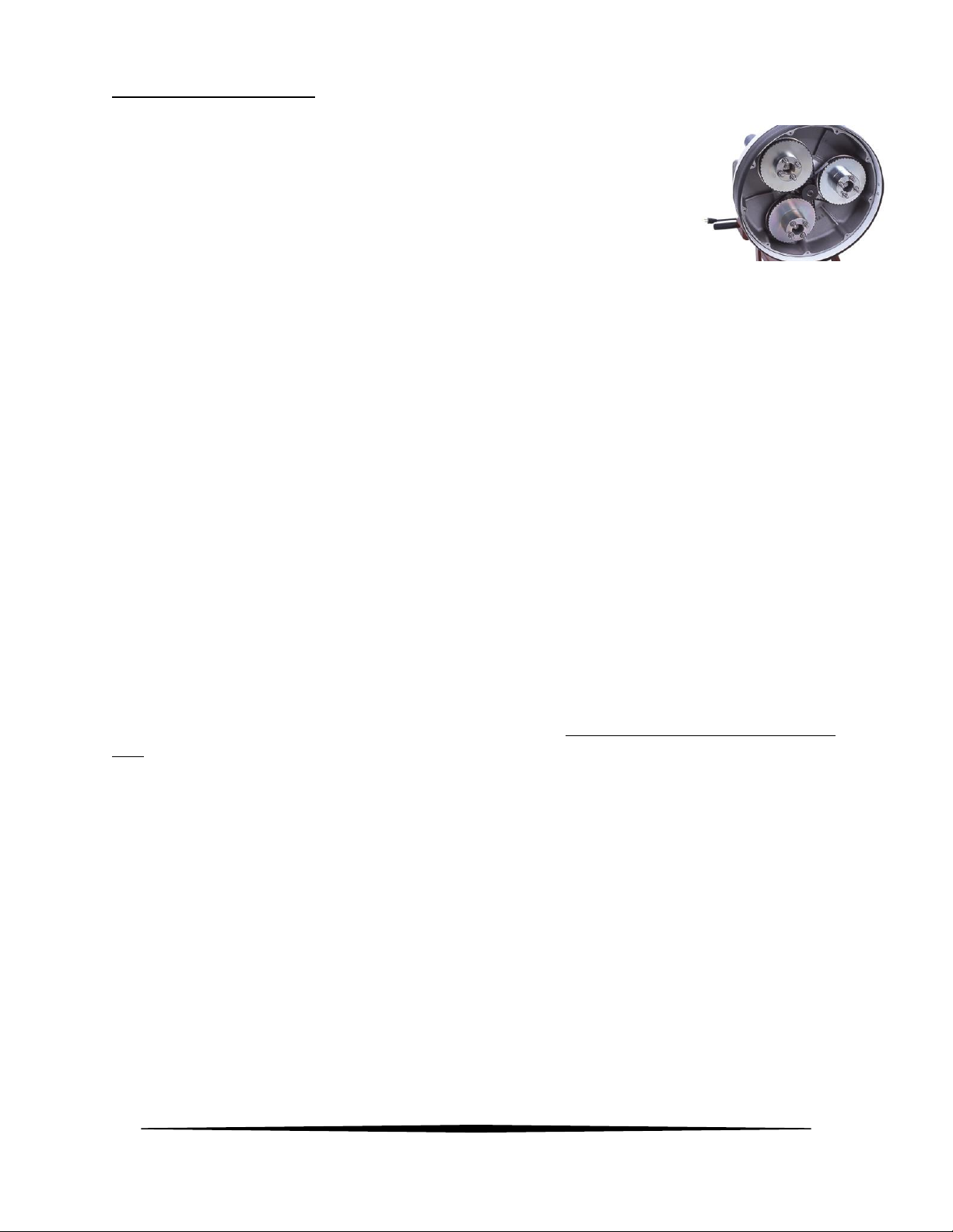
7) Locate bolt in center of center driving pulley. While holding one of the large driven pulleys to prevent
rotation, remove this center bolt and its flat washer. On some machines this removal requires a hex
(Allen) wrench while later machines require a 7/16 wrench or socket.
8) On some older machines, retaining plates were not used on the face of the driven pulleys. If your
machine is configured this way go to step 11.
9) On machines with old style plates, each driven pulley has (3) Allen socket screws holding the retainer
plates in place. Remove these (9) screws and (3) retaining plates then go to step 11.
10) On machines with newer retaining plate design, only remove the single ¼-20 hex bolt from each of
the driven pulleys. Then rotate the retaining plate slightly until keyhole openings in plate allow removal.
If plate will not rotate, loosen button head screws slightly and rotate plate. There is no need to remove
button head screws.
11) With retaining plates removed and using gloves, pull the belt away from large pulley using a flat
screwdriver while slowly rotating the pulley. Be careful not to pinch fingers between belt and pulley.
Repeat until belt is off pulley. Repeat this process until all three belts have been removed.
12) Remove center driving pulley from motor shaft. This may require prying behind pulley(s) with a large
flat screwdriver or a small pry bar. In some extreme cases it may even require the use of a pulley puller
tool. Also remove square key.
13) With center pulley removed, locate retaining ring at center of bowl (just behind where center pulley
was before removal). Wear safety glasses. Using a pair of retaining ring plyers, remove this retaining
ring.
14) Using a clean cloth, wipe away any dust or dirt from the groove where retaining ring was located.
15) Using two of the large pulleys as handles, pull away from machine. This should allow entire inner
bowl with large pulleys intact to slide out of machine. If bowl will not slide out try lifting up on pulleys at
the same time while pulling away from machine. In rare instances it may require renting a Harmonic
Balancer Removal tool from an auto parts store to extract the bowl. If this type of difficulty is
experienced contact factory for further guidance.

11
Inner Bowl Bearing Replacement
With the bowl removed, upper bowl bearings can be serviced.
This job requires a set of retaining ring plyers, safety glasses and the proper replacement bearings. The
bearings used here are 6009 bearings with double seals. These are available from Onfloor, part number
245666. It is very important to wear the safety glasses especially when removing and installing the
retaining rings. If you do not have retaining ring plyers they can be purchased at Lowes, Home Depot,
Harbor Freight, and other tool stores for about $20.
The steps to remove the inner bowl are covered on page 10 so we will address what to do after removal
is accomplished.
When replacing the bearings in the top of the Inner Bowl there are some things that should be pointed
out to insure longer life and better performance. The first has to do with the method used to remove
and install the new bearing. Remove the retaining ring and proceed to the steps below.
Installation Using a Press
The best method to remove and install new bearings is to take the inner bowl assembly to a hydraulic
press and press the bearings in and out. When using this method, it is important to properly support the
cast aluminum bowl so as to prevent cracking the casting. This is accomplished by supporting the casting
as close as possible to the center while allowing room for the bearings to exit. See illustration A. When
pressing the old bearings out it is acceptable to use almost any device as a pushing tool as long as it will
fit through the center opening without touching the casting. This means a piece of metal tubing or rod
or even a piece of wood that will fit through a 2-11/16” diameter hole. We do not need to be cautious
about damaging the old bearings to remove.
When installing the new bearings, first clean the surface of the opening where the bearings are to enter.
Support the casting properly (See illustration A on page 12). Use a pusher device that will contact the
OUTER RACE. It is important that you do NOT press on the inner race to install the bearings. This will
damage the bearings and shorten their life. The best choice for a pushing tool is a round rod/pipe or
piece of wood that is just under 3” diameter that will pass through the 2.95” opening in the casting.
Many people find a large socket that makes contact with the outer race but fits through the opening.
The first bearing must be pressed all the way down to the bottom of the cavity, followed by the spacer
ring (you don’t want to forget this) then, finally the last bearing. When properly installed the last bearing
will be below the retaining ring groove and the retaining ring should go in easily.
Installation without a Press
When using this method, use a short piece of wood and a mallet/hammer to drive the old bearings from
the cast inner bowl. I suggest wood to prevent causing damage to the casting during this step. Support
the casting on 2 blocks of 2 x 4 or 4 x 4 lumber (see illustration on page 12). We don’t have to be
cautious about damaging the old bearings. When installing the new bearings, first clean the surface of
the opening where the bearings are to enter. Turn the bowl over and rest its center on a short block of 4
x 4 lumber. (See illustration A on page 12). Place the first bearing in the center opening and place a flat
piece of wood or steel across the top of the bearing. It is important that you drive the bearing in straight
AND that you do this by applying force to the outer race. It is OK that the flat steel or wood is contacting
the inner race as long as the outer race is also in contact. Tap the wood/steel plate with the hammer

12
and slowly drive the bearing until it is flush with the top of the casting. Now there are 2 ways to
proceed. One is to find a round object (large socket, steel tube, steel rod, etc.) that will contact the outer
race and also fit through the opening in the casting and use this object to further tap the bearing to the
bottom of the cavity. The other way is to use a short wooden dowel ½ or ¾” in diameter and to tap the
outer race with small taps as you work the dowel around the perimeter of the outer race as you
gradually drive the bearing down to the bottom. When the first bearing is installed, follow with the
spacer ring (you don’t want to forget this) then; repeat the same process with the top bearing. Then
install the retaining ring.
An Important Detail
After the bearings and retaining ring has been installed but before the bowl is installed, it is very
important that you cover the top of the upper bearing with grease. It makes no difference what the
quality of the grease is because it is not being used for lubrication it is serving as a barrier to prevent air
born concrete dust from reaching the top bearing. We suggest using grade 3 wheel bearing grease with
a putty knife and fill the entire cavity (about 3/16” deep) that exists above the top bearing. This will
prevent dust infiltration which is the main cause of this bearing’s failure. The attached Photo shows the
top bearing before and after grease has been applied.

13

14
Pulley Bearing Replacement
This job requires a set of retaining ring plyers, safety glasses and the proper replacement bearings as
well as some general hand tools. The bearings used here are 6203 bearings with double seals. These are
available from Onfloor, part number 245321. It is very important to wear the safety glasses especially
when removing and installing the retaining rings. If you do not have retaining ring plyers they can be
purchased at Lowes, Home Depot, Harbor Freight, and other tool stores for about $20.
Once the bearings are determined to be in need of replacement, follow the steps below to remove the
pulley(s) that need replacement bearings:
1. With the handle in the straight up position, tilt the machine to its side so the machine is resting
on the side of the outer bowl and one of the handle grips. This makes the machine stable and
less likely to tip over.
2. Remove the tools.
3. Remove the 9 fasteners around the perimeter of the dust cover. On some machines these were
Philips head screws. On later machines these are ¼-20 hex head bolts requiring a 7/16 socket
and rachet or a 7/16 wrench. Remove dust cover.
4. Remove belt keeper plates on the face of each pulley. To do this you will need to remove the 3
small screws on older machines. On later model machines it is only necessary to remove the
single hex head bolt on each pulley. Then rotate the keeper plate a few degrees until the
keyhole openings in the plate align with the remaining screw heads and lift the plate off. An
upgrade kit is available to change to this new keeper plate system. For all 16” machines built
since 2007 and for 20” machines built prior to the heavy-duty belt system the part number for
the upgrade kit is 603775. For 20” machines with heavy duty belt systems the kit number is
603783. There are some much older machines built before 2007 that have pulleys without
holes that the kits will not work on.
5. Wear gloves to work the belt off the pulley teeth while slowly rotating pulley. Belt will come off
the large pulley. Be careful not to pinch your fingers.
6. To remove pulley, use a deep well 15/16 socket wrench to remove the locking hex nut located
down inside the pulley center opening. The flat washer located behind the nut is a 16mm flat
washer and not a standard SAE type so be careful not to lose them as they may be challenging
to purchase locally. Pull the pulley straight out and away from the machine. There is also a small
spacer located behind the pulley. Be careful not to lose this as well.
With the pulley removed we can proceed with bearing replacement. Look at the pulley from the back
and you will see the retaining ring that secures the bearings in place. Wearing your safety glasses and
using the retaining ring plyers remove the retaining ring.
Installation Using a Press
The best method to remove and install new bearings is to take the pulley to a hydraulic press and press
the bearings in and out. When using this method, it is important to properly support the pulley to allow
space for the old bearings to exit. This is accomplished by supporting the pulley as close to the center as

15
practical using 2 pieces of 2 x 4 lumber or 2 pieces of equal thickness steel. When pressing the old
bearings out it is acceptable to use almost any device as a pushing tool as long as it will fit through the
center opening without touching the pulley. This means a piece of metal tubing or rod or even a piece of
wood that will fit through a 1.29” diameter hole. The same 15/16 socket used to remove the nuts works
well for this. We do not need to be cautious about damaging the old bearings to remove. (see
illustration page 16)
When installing the new bearings, first clean the surface of the opening where the bearings are to enter.
If your pulley has the 4 drive pins installed, I suggest removing them for this process. You will need a
7/16 deep well socket for this. Stand the pulley in the press resting on its front face. Use a pusher device
that will contact the OUTER RACE. It is important that you do NOT press on the inner race to install the
bearings. This will damage the bearings and shorten their life. The best choice for a pushing tool is a
round rod/pipe or piece of wood that is 1-1/2” diameter that will pass through the 1.57” opening in the
pulley. (see illustration on page 16) Many people use a large socket that makes contact with the outer
race but fits through the opening. The first bearing must be pressed all the way down to the bottom of
the cavity, followed by the spacer ring (you don’t want to forget this) then, finally the last bearing. Be
careful not to over press especially if you left the drive pins in the pulley. When properly installed the
last bearing will be below the retaining ring groove and the retaining ring should go in easily.
Installation without a Press
When using this method, use a short piece of wood (or 15/16 socket) and a mallet/hammer to drive the
old bearings from the cast inner bowl. Support the pulley on a piece of wood to prevent damaging it.
We don’t have to be cautious about damaging the old bearings. When installing the new bearings, first
clean the surface of the opening where the bearings are to enter. Turn the pulley over and rest its front
face (or drive pins if present) on the piece of wood. Place the first bearing in the center opening and
place a flat piece of wood or steel across the top of the bearing. It is important that you drive the
bearing in straight AND that you do this by applying force to the outer race. It is OK that the flat steel or
wood is contacting the inner race as long as the outer race is also in contact. Tap the wood/steel plate
with the hammer and slowly drive the bearing until it is flush with the top of the pulley. Now there are 2
ways to proceed. One is to find a round object (large socket, steel tube, steel rod, etc.) that will contact
the outer race and also fit through the opening in the pulley and use this object to further tap the
bearing to the bottom of the cavity. The other way is to use a short wooden dowel ½ or ¾” in diameter
and to tap the outer race with small taps as you work the dowel around the perimeter of the outer race
as you gradually drive the bearing down to the bottom. When the first bearing is installed, follow with
the spacer ring (you don’t want to forget this) then; repeat the same process with the top bearing. Then
install the retaining ring.
Reinstall drive pins, pulley, belts, keeper plates, dust cover in reverse order of removal.

16

17
General Safety Precautions
This machine is designed for surfacing concrete and sanding wood floors. All
operators and maintenance personnel should read and understand the safety
procedures with this floor machine.
1) All personnel in the immediate work area must wear safety glasses with side shields whenever the
machine is in operation. Protective clothing is also recommended. Long sleeve shirts and safety shoes
should be worn. Avoid wearing loose clothing.
2) DO NOT attempt to service or replace attachments while the machine is running or connected to a
power source.
3) DO NOT operate this floor machine in the rain or in areas where liquids could enter the electrical
components of the machine.
4) Keep the power cord away from the revolving heads to avoid damage.
5) Check main power supply to assure that you are connecting the equipment to a proper dedicated
service.
Machine Maintenance
1) Unplug the machine.
2) After each use, wipe off machine with a clean cloth.
3) Empty the vacuum you are using in accordance with specific manufacturer’s safety & operation
instructions.
4) Remove the dust cover from the bottom of the machine and vacuum out the inner bowl.
5) Check for loose parts and fasteners.
6) Check the power cord for any breaks in the wire. Breaks will most likely occur near the plug
or switch. Repair or replace any breaks immediately.

18
OF20SL Handle & Base Assembly Drawing & Parts List
ITEM
DESCRIPTION
QTY
PART
NO.
ITEM
DESCRIPTION
QTY
PART
NO.
1
HANDLE ASSY LO SPEED 115 VOLT
1
296791
15
SCREW, #10-24 X 1
1
335169
2
QUICK RELEASE PIN W/CABLE
1
456896
16
SWITCH BOX PLATE
1
281903
3
CIRCUIT BREAKER, 25 AMP
1
607495
17
SCREW, #8-32 X 1/2
4
385387
4
STRAIN RELIEF
1
285420
18
BRONZE BUSHING
2
491055
5
30 FT POWER CORD W/PLUG
1
491160
19
SHOULDER BOLT .37-16 X 1/2
2
491063
6
MOTOR CORD W/FEMAL PLUG
1
490210
20
WHEEL BASE ASSY
1
296570
7
WIRE NUT
1
350648
21
6 X 2 WHEEL
2
490903
8
TERMINAL, FLAG
2
379166
22
PALNUT
2
490881
9
WIRE, JUMPER
1
435120
23
NUT, STAR WASHER #10
2
331201
10
TERMINAL, RING #16-14
1
217751
24
WIRE RETAINER ASSY
1
479152
11
TOGGLE SWITCH
1
490148
25
SCREW, ALLEN HD 1/4-20 X 5/8
1
457310
12
RUBBER HANDLE GRIP
2
490180
26
LOCK WASHER 1/4
1
342858
13
DRIVE RIVET
2
490202
27
TERMINAL, RING #12
1
217778
14
GUARD, SWITCH
1
491233
28
GROMMET
1
491099
29
LOCKWASHER,# 8,INT TOOTH
4
380709

19
OF20SH Handle & Base Assembly Drawing & Parts List
ITEM
DESCRIPTION
QTY
PART
NO.
ITEM
DESCRIPTION
QTY
PART
NO.
1
HANDLE ASSY 230 VOLT HI SPEED
1
296732
14
GROMMET
1
490199
2
QUICK RELEASE PIN W/CABLE
1
456896
15
SCREW, #10-24 X 1
1
335169
3
SWITCH COVER PLATE
1
221767
16
SWITCH BOX PLATE
1
281903
4
STRAIN RELIEF
1
285420
17
SCREW, #8-32 X 1/2
4
385387
5
50 FT POWER CORD
1
493163
18
BRONZE BUSHING
2
491055
6
MOTOR CORD W/FEMALE PLUG
1
490229
19
SHOULDER BOLT .37-16 X 1/2
2
491063
7
SCREW, #6-32 X .37, TRS PHLP
2
377155
20
WHEEL BASE ASSY
1
296570
8
TERMINAL, SPADE, INSUL 14-16 GA
4
490245
21
6 X 2 WHEEL
2
490903
9
PLUG, 30 AMP MALE (5 HP MOTOR)
1
468800
22
PALNUT
2
490881
10
TERMINAL, RING XXX
1
429015
23
NUT, STAR WASHER #10
2
331201
11
TOGGLE SWITCH
1
479187
24
WIRE RETAINER ASSY
1
479152
12
RUBBER HANDLE GRIP
2
490180
25
SCREW, ALLEN HD 1/4-20 X 5/8
1
457310
13
WASHER, TOOTH LOCK, #8
4
380709
26
LOCK WASHER 1/4
1
342858

20
OF20SL & SH Outer Bowl Drawing & Parts List
ITEM
DESCRIPTION
QTY
PART
NO.
ITEM
DESCRIPTION
QTY
PART
NO.
1
2 HP MOTOR ASSY, 115 V (1760 RPM)
1
299774
20
ROUND HEAD SCREW, 1/4-20 X 3/4
3
342831
5 HP MOTOR ASSY, 230V (3450 RPM)
1
299782
21
SOCKET CAP SCREW 1/4-20 X 5/8
4
457310
2
GASKET, CAP
1
349496
22
NUT, NYLOCK 1/4-20
3
380784
3
CAP
1
349585
23
FLET GASKET
1
493066
4
HOSE ADAPTER
1
349445
24
1.75 EXTERNAL SNAP RING
1
491292
5
RIVET
6
318906
25
RUBBER DUST SKIRT
1
491926
6
KEY, SQUARE .19 X 2.05
1
491306
26
MALE HOOK & LOOP STRIP
1
491659
7
SET SCREW (2 HP ONLY)
2
490849
27
BALDOR FAN COVER FOR 230V MOTOR
1
246468
8
MOTOR SHAFT EXT. (2 HP ONLY)
1
490857
28
CAPACITOR COVER BALDOR MOTOR
2
295671
9
KEY, SQUARE .19 X 1.5 (2 HP ONLY)
1
606243
29
COOLING FAN BALDOR MOTOR
1
605840
10
MOTOR MOUNT PLATE ASSY
1
490326
30
CAPACITOR, START, BALDOR 3450 RPM
1
271938
11
MOUNTING BRACKET
2
606227
CAPACITOR, RUN, BALDOR 3450 RPM
1
241946
12
BOWL HANDLE
2
490385
CAPACITOR, START, LEESON 1760 RPM
1
606820
13
WEIGHT KNOB
3
491632
CAPACITOR, RUN, LEESON 1760 RPM
1
606812
14
20" OUTER BOWL ASSY
1
291641S
31
STRAIN RELIEF
1
497657
15
LOCK WASHER 5/16
4
316113
32
PIGTAIL W/MALE PLUG
1
495786
16
SOCKET CAP SCREW 5/16-18 X 1
4
490350
33
NUT, WIRE (QTY 2 REQ'D ON 1.5 HP)
3
350648
17
FLAT WASHER .37 ID X .87 OD
4
327433
34
EXHAUST PORT
2
310999
18
LOCK WASHER 3/8
4
368849
35
GASKET, EXHAUST PORT
2
320986
19
3/8-16 X 1" HEX BOLT
4
368830
28# WEIGHT (OPTIONAL) NOT SHOWN
1
492442
This manual suits for next models
1
Table of contents
Other Onfloor Floor Machine manuals
Popular Floor Machine manuals by other brands

U.S. Products
U.S. Products KING COBRA 310 Information & operating instructions

Nobles
Nobles Marksmant 412 Specifications

BETCO
BETCO E12327-00 BIG BERTHA XSM30 Operator and parts manual

NSS
NSS CHARGER 2717 DB Operation manual

Nilfisk-Advance
Nilfisk-Advance SR 2000 Instructions for use

Clemas & Co
Clemas & Co GUMPAK Operator's manual