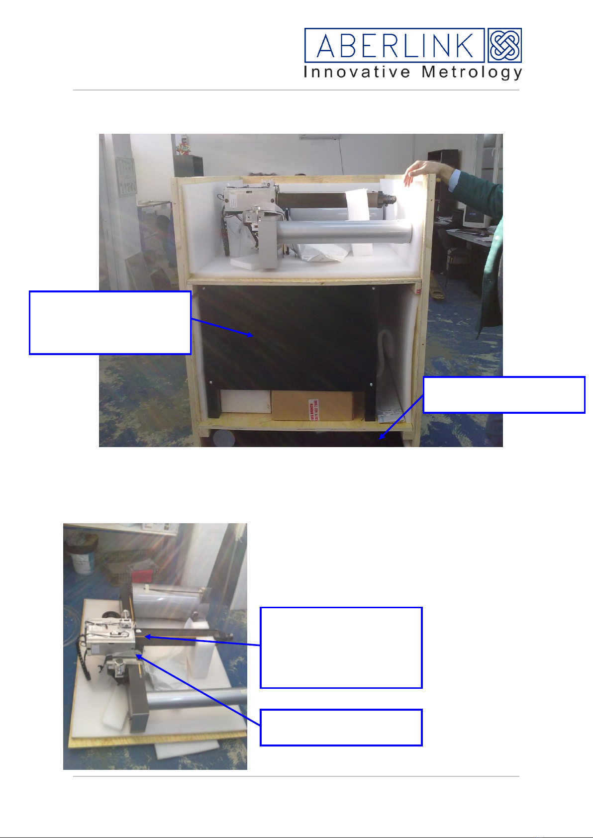
manuals.online logo
Brands
  1. Home
  2. •
  3. Brands
  4. •
  5. ABERLINK
  6. •
  7. Measuring Instrument
  8. •
  9. ABERLINK Axiom Too User manual

ABERLINK Axiom Too User manual

Popular Measuring Instrument manuals by other brands

Powerfix Profi 278296 Operation and safety notes

Powerfix Profi

Powerfix Profi 278296 Operation and safety notes

Test Equipment Depot GVT-427B user manual

Test Equipment Depot

Test Equipment Depot GVT-427B user manual

Fieldpiece ACH Operator's manual

Fieldpiece

Fieldpiece ACH Operator's manual

FLYSURFER VIRON3 user manual

FLYSURFER

FLYSURFER VIRON3 user manual

GMW TG uni 1 operating manual

GMW

GMW TG uni 1 operating manual

Downeaster Wind & Weather Medallion Series instruction manual

Downeaster

Downeaster Wind & Weather Medallion Series instruction manual

Hanna Instruments HI96725C instruction manual

Hanna Instruments

Hanna Instruments HI96725C instruction manual

Nokeval KMR260 quick guide

Nokeval

Nokeval KMR260 quick guide

HOKUYO AUTOMATIC UBG-05LN instruction manual

HOKUYO AUTOMATIC

HOKUYO AUTOMATIC UBG-05LN instruction manual

Fluke 96000 Series Operator's manual

Fluke

Fluke 96000 Series Operator's manual

Test Products International SP565 user manual

Test Products International

Test Products International SP565 user manual

General Sleep Zmachine Insight+ DT-200 Service manual

General Sleep

General Sleep Zmachine Insight+ DT-200 Service manual

Sensa Core Lacto Spark user manual

Sensa Core

Sensa Core Lacto Spark user manual

VOLTCRAFT UTS-1980 operating instructions

VOLTCRAFT

VOLTCRAFT UTS-1980 operating instructions

EBCHQ 94915 Operation manual

EBCHQ

EBCHQ 94915 Operation manual

Balluff BIP LD2-T017-01-EP-S4 Series user guide

Balluff

Balluff BIP LD2-T017-01-EP-S4 Series user guide

Pulsar IMP Lite Series instruction manual

Pulsar

Pulsar IMP Lite Series instruction manual

ETCR 6800 user manual

ETCR

ETCR 6800 user manual

manuals.online logo
manuals.online logoBrands
  • About & Mission
  • Contact us
  • Privacy Policy
  • Terms and Conditions

Copyright 2025 Manuals.Online. All Rights Reserved.

ABERLINK LTD |VATCH LANE |EASTCOMBE |GLOUCESTERSHIRE |GL6 7DY |UK
Tel : +44 (0)1453 884461 | Fax : +44 (0)1453 882348 |
Email : [email protected] | Web : www.aberlink.com
Registered in England No. 7642245 |
VAT Registration No. GB 108 3075 37
Axiom Too installation manual
Includes HS spec.
Last update 1st March 2017
Issue 2
ABERLINK LTD |VATCH LANE |EASTCOMBE |GLOUCESTERSHIRE |GL6 7DY |UK
Tel : +44 (0)1453 884461 | Fax : +44 (0)1453 882348 |
Email : sales@aberlink.co.uk | Web : www.aberlink.com
Registered in England No. 7642245 |
VAT Registration No. GB 108 3075 37
The machine will arrive in a single crate,
Package 1 Wooden crate
Contents Granite
Bench
Computer equipment
Machine Accessories
Bridge
Unpacking Package 1
Remove the lid of the crate by removing the screws to reveal the bridge
Tools Required.
15mm Spanner
Set of metric allen keys
5.5mm Spanner
Large flat blade screwdriver
Lifting equipment
Small flat blade screwdriver
Calibration equipment
Wire cutters
Cross head screwdriver
Next, remove this end panel, notice the
position of the bridge, the other sides will
have the shelf supports, do not remove
those
ABERLINK LTD |VATCH LANE |EASTCOMBE |GLOUCESTERSHIRE |GL6 7DY |UK
Tel : +44 (0)1453 884461 | Fax : +44 (0)1453 882348 |
Email : sales@aberlink.co.uk | Web : www.aberlink.com
Registered in England No. 7642245 |
VAT Registration No. GB 108 3075 37
Once this panel is removed you can unload the parts, starting with the bridge. Use the
packaging to place the bridge on whilst setting up machine.
Notice in this picture the z axis is still being
supported. Also place some foam under the x axis
so that the back of the carriage is not touching the
floor. Also notice the supports on the bridge for
transit.
Bench, and all loose
packages including the pc
controller, covers etc.
Granite base located at the
bottom of the crate
Carriage is tightly strapped
in two positions
Transit screws lock the z
axis, two screws which
have tags on retain a piece
of plastic which clamps the
z quill
ABERLINK LTD |VATCH LANE |EASTCOMBE |GLOUCESTERSHIRE |GL6 7DY |UK
Tel : +44 (0)1453 884461 | Fax : +44 (0)1453 882348 |
Email : sales@aberlink.co.uk | Web : www.aberlink.com
Registered in England No. 7642245 |
VAT Registration No. GB 108 3075 37
Locating the machine.
Locate the bench where the machine is to be positioned, allow additional room for when
the bridge is fitted. See below for minimum clearance.
Once you have
removed the bridge, the
shelf can slide out.
Remove the bench and
loose boxes, then
remove the next shelf
(remove screws). Then
it is possible to remove
remaining sides to get
easy access to the
granite.
In this picture the
location studding is
attached to the granite,
in some cases it will be
placed in a box.
Front
Allow 500mm
Allow 400mm
Allow 300mm
Monitor arm option,
allow room as shown
Allow 250 mm
Allow 600 mm
ABERLINK LTD |VATCH LANE |EASTCOMBE |GLOUCESTERSHIRE |GL6 7DY |UK
Tel : +44 (0)1453 884461 | Fax : +44 (0)1453 882348 |
Email : sales@aberlink.co.uk | Web : www.aberlink.com
Registered in England No. 7642245 |
VAT Registration No. GB 108 3075 37
Lifting the granite
The granite can be either solid granite or honeycomb, the weights are as follows
Honeycomb Solid
600 Y axis 95 kg 600 Y axis 350 kg
900 Y axis 127kg 900 Yaxis 470 kg
1200 Y axis 590 kg
1500 Y axis 705 kg
Honeycomb granite will be attached to the bench with M10 studding, Solid granite will be
supported via rubber feet, also supplied will be anti tip feet.
Solid Granite
Do not attempt to manually lift solid granite, it will be necessary to use hydraulic lifting
equipment. The bench is not designed to be moved with the granite in place.
When loading the granite, be sure to set enough clearance on the feet to enable the fork
lift forks to be removed once the granite is lowered.
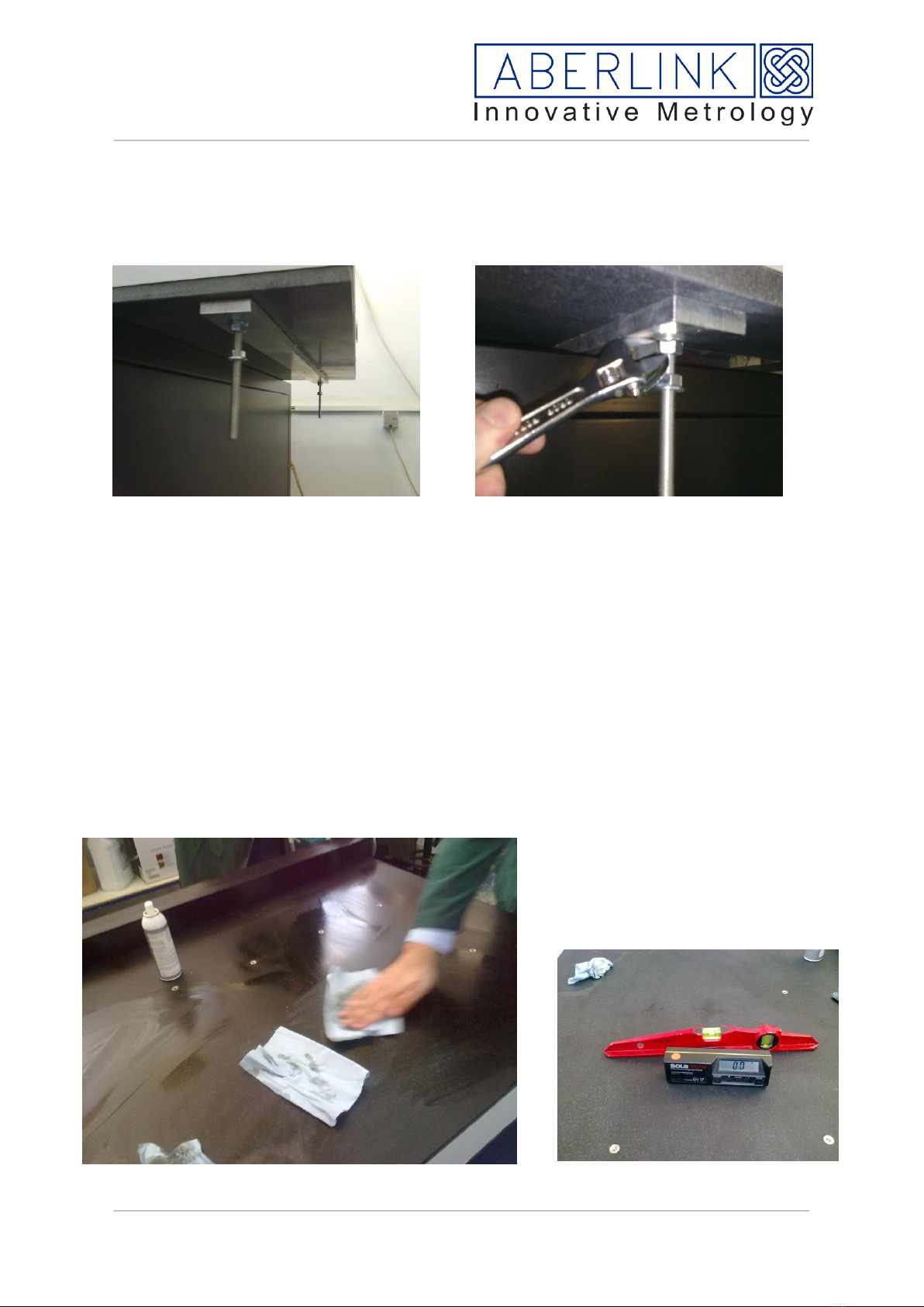
To aid levelling, set all feet to the same height
Have the anti-tip feet set lower than the location feet, and raise once the granite is located
and levelled.
Position the granite so the front of the granite overhangs the front by 20mm, and have the
granite located equi-distance from the left and right side.
Once in position, clean the granite and the y axis scale on the right hand side.
Honeycomb granite
The 600mm machine can be lifted quite comfortably by 4 people if necessary.
Once the granite is lifted you can locate the studding, there are two holes at the front of the
machine and one at the back in the centre position. If placing the granite onto the bench
for this task, then position on an angle to allow access.
Screw in the stud until it stops then unwind one-quarter turn, then attach and lock with the
supplied M10 nut, use 15mm spanner. Also attach another M10 nut with the flange facing
down. Set all to the same distance, allow for fork clearance if using fork lift.
ABERLINK LTD |VATCH LANE |EASTCOMBE |GLOUCESTERSHIRE |GL6 7DY |UK
Tel : +44 (0)1453 884461 | Fax : +44 (0)1453 882348 |
Email : sales@aberlink.co.uk | Web : www.aberlink.com
Registered in England No. 7642245 |
VAT Registration No. GB 108 3075 37
Up to Dec 2012
If using a scissor table, it is possible to remove the printer shelf by removing 6 bolts
located under the bench, and also by removing the keyboard tray –release the plastic
fingers on the tray runners, one finger up, the other down. Next it is possible to wheel the
granite into position, and easily locating the studs over the three holes, and lowering the
granite with good control, by releasing the valve on the scissor table.
From Jan 2013 (new design of bench)
It is possible to move the bench and granite together with a pallet truck to achieve position.
The pallet truck must come in from the side, do no insert from front or back as there is no
support.
Clean the granite surface, and also
clean the gold scale tape. Contact
Aberlink for supply of special
granite cleaner.
ABERLINK LTD |VATCH LANE |EASTCOMBE |GLOUCESTERSHIRE |GL6 7DY |UK
Tel : +44 (0)1453 884461 | Fax : +44 (0)1453 882348 |
Email : sales@aberlink.co.uk | Web : www.aberlink.com
Registered in England No. 7642245 |
VAT Registration No. GB 108 3075 37
The purpose of levelling the granite is to aid the dynamics of the machine, so the motors
are not working against gravity. High tolerance levels are not necessary. Check in y
direction and x direction, and use the nuts on the studding to adjust. Once done, fit the
last M10 nut and tighten against the underside of the bench.
Locate the regulator set and fit to the rear
of the machine in the holes provided.
See below for benches manufactured after
2014
Prior to pressure sensor
8mm O/dia tube to airbearings –
connect pipe from the machine
6mm O/dia tube to the z
balance –connect pipe
from the machine
Short length of
6mm tube
Air supply in.
Fitted with 8mm
push connector,
placed in ¼ bsp
port
Tee piece
Solenoid
block, if CNC
= Air Flow
Regulator with filter and
gauge
Continuous supply to z balance
ABERLINK LTD |VATCH LANE |EASTCOMBE |GLOUCESTERSHIRE |GL6 7DY |UK
Tel : +44 (0)1453 884461 | Fax : +44 (0)1453 882348 |
Email : sales@aberlink.co.uk | Web : www.aberlink.com
Registered in England No. 7642245 |
VAT Registration No. GB 108 3075 37
After pressure sensor
Design from 2014, regulator fitted to
side of bench, also in situ is the Z
balance regulator. At the rear of the
bench is an 8mm push fit union.
Customer to supply 8mm o/dia tubing, or
remove fitting and screw into ¼ BSP
fitting
Inside the bench you can also see the
solenoid and a pressure sensor.
Assembled at the factory, the air
pressure sensor has additional cable to
connect to the PC, this links the I/O to
the IO1 connector on the deva card
Picture of solenoid and pressure
sensor. Sensor is connected via
input 1 on the deva card. It will
disable the drives in case of
pressure drop.
8mm O/dia tube to airbearings –
connect pipe from the machine
6mm O/dia tube to the z
balance –connect pipe
from the machine
Air supply in.
Fitted with 6mm
push connector,
placed in ¼ bsp
port
Tee piece
Solenoid
block
= Air Flow
Regulator with filter
and gauge
Continuous supply to z balance
Pressure sensor,
set to 0.3 Mpa
Twin core cable to
PC
Z
balance
regulator
ABERLINK LTD |VATCH LANE |EASTCOMBE |GLOUCESTERSHIRE |GL6 7DY |UK
Tel : +44 (0)1453 884461 | Fax : +44 (0)1453 882348 |
Email : sales@aberlink.co.uk | Web : www.aberlink.com
Registered in England No. 7642245 |
VAT Registration No. GB 108 3075 37
The pressure sensor should be set to around 0.35, there is gauge on the unit itself. See
below.
The gauge position can be adjusted by loosening the locking nut, then turning the screw.
If you also use input 1 on axistuner input/output screen, you should see at what pressure
on the regulator the input is switched.
ABERLINK LTD |VATCH LANE |EASTCOMBE |GLOUCESTERSHIRE |GL6 7DY |UK
Tel : +44 (0)1453 884461 | Fax : +44 (0)1453 882348 |
Email : sales@aberlink.co.uk | Web : www.aberlink.com
Registered in England No. 7642245 |
VAT Registration No. GB 108 3075 37
Locating the bridge
The bridge can be located onto the machine with two people, with one person on each leg
of the machine. The person holding the right leg locates the leg over the granite rail, while
the second person holding the left leg maintains the bridge so that the top of the x axis is
level, and keep the bridge square to the granite rail, this is very important to do as very
little clearance between the airbearings on the right leg and the rail. If the left side is not
held square and level the angle will prove impossible to locate.
Consideration must be paid to the trailing cables, and also the airbearings, the bearings
are held against the leg by small pieces of double sided tape, check the tape is still
capable of holding the bearing, otherwise replace with a new piece. DO NOT ADJUST
THE SCREWS BEHIND THE BEARINGS –THEY ARE FACTORY SET FOR XY
SQUARENESS
The left leg packaging should stay on the leg and only be removed once the bridge is
located.
If you are careful you can remove the protective
paper without losing the air bearing location.
Remove 3 sides of the sticking tape then apply
a small amount of lift to the x beam whilst
pulling on the last piece of tape.
Once removed please ensure the airbearing is
located properly, if not located properly form
errors will be present during inspection.
Only remove
once the bridge
is on the
machine