Abit BX6 User manual

PartNo:MN-116-2B1-61 Rev:1.11
Theinformationinthisdocumentissubjecttochangewithoutnotice and
doesnotrepresentacommitmentonpartofthevendor,whoassumesno
liabilityorresponsibilityforanyerrorsthatmay appearinthismanual.
Nowarrantyorrepresentation,eitherexpressedorimplied,ismadewith
respecttothequality,accuracyorfitness foranyparticularpartofthis
document.Innoeventshall themanufacturerbeliablefordirect,
indirect,special,incidentalorconsequentialdamagesarisingfromany
defectorerrorinthismanualorproduct.
Productnamesappearinginthismanualareforidentificationpurposeonly
and trademarksand productnamesorbrand namesappearinginthis
documentarepropertyoftheirrespectiveowners.
ThisdocumentcontainsmaterialsprotectedunderInternationalCopyright
Laws.All rightsreserved.Nopartofthismanualmay bereproduced,
transmittedortranscribedwithouttheexpressedwrittenpermissionofthe
manufacturerand authorsofthismanual.


BX6 Pentium®II Mainboard
USER’SMANUAL
TableofContents
Chapter1IntroductionofBX6Features
¬Specifications.....................................................……...1-1
-Layoutdiagram............................................................1-3
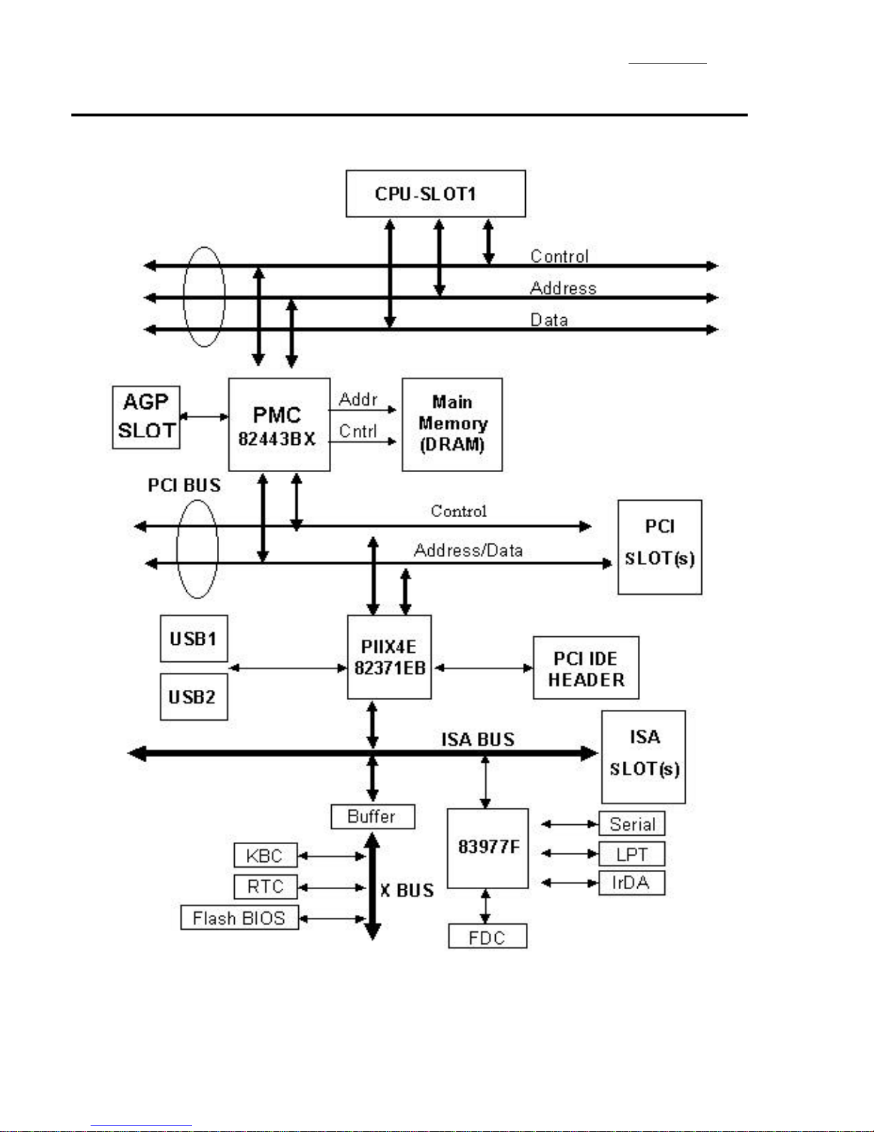
®Thesystemblockdiagram.............................................1-4
Chapter2InstallingtheMainboard
¬InstallingtheMainboardtotheCasing.........................2-3
-StandardExternalConnectors......................................2-4
®JumperandSwitches....................................................2-9
¯InstallationoftheCPU...............................................2-11
°InstallingSystemMemory
¡i
DRAMMemory
¡j
2-14
Chapter3IntroductionofBIOS
¬CPUSetup ¡i CPUSOFTMENU™II ¡j………… 3-3
-StandardCMOSSetup Menu…………………..…..…3-7
®BIOSFeaturesSetup Menu…………………..……….3-9
¯ChipsetFeaturesSetup Menu…………………..……3-15
°PowerManagementSetup Menu…………….………3-17
±PCI&OnboardI/OSetup ……………………………3-22
²LoadBIOSDefaults………………………………….3-26
³LoadSetup Defaults……………………………….. ..3-26
´PasswordSetting…………………………………….3-27
µIDEHDD AutoDetection……………………………3-28
Chapter4BusMasterIDEDriver

AppendixAQuickInstallation
AppendixBGeneralDiscussionaboutHDD Installation
AppendixCFlashBIOSUserInstructions
AppendixDHowtoinstall UltraDMA/33 drive
AppendixEHowtoinstall thePCIbridgedriverfor440BXchipset
AppendixFTechnicalSupport

IntroductionofBX6Feature1-1
Chapter1Introduction ofBX6Feature
ThismainboardisdesignedforthenewgenerationCPU.ItsupportstheIntelCPU
SLOT1(PentiumII),up to512MBofmemory,superI/O,andGreenPCfunctions.The
mainboardprovideshighperformance fortheserversystemandmeetstherequirements
ofthedesktopsystemformultimediainthefuture.
¬Specifications
1.
CPU
lCPUSOFTMENU™II eliminatestheneedforjumpersorDIPswitches
neededtosetCPUparameters
lEmploysswitchingtyperegulatorstostabilize CPUoperation
lSupports66MHzand100MHzCPUexternalclockspeeds
lSupportsPentiumII 350~400MHzprocessorcartridge(Basedon100 MHz)
andPentiumII 233~333MHzprocessorcartridge(Basedon66 MHz).
2.
Chipset
lIntel440BXchipset(82443BXand82371EB)
lSupportsUltraDMA/33 IDEprotocol
lSupportsAdvancedConfigurationandPowerManagementInterface(ACPI)
lAcceleratedGraphicsPortconnectorsupportsAGP1xand2xmode
(Sideband)3.3Vdevice
3.
CacheMemory
lLevel1andLevel2cachebuiltintoIntelPentiumII processorpackage.
4.
Memory(DRAM)
lFour168-pinDIMM socketssupportSDRAM
lSupportsup to512MBytes
lECC support

1-2Chapter1
5.SystemBIOS
lAWARDBIOS
lSupportsPlug-and-Play(PnP)
lSupportsAdvancedConfigurationPowerInterface (ACPI)
lSupportsDesktopManagementInterface (DMI)
lYear2000 Compliant
6.
MultiI/O Functions
lFloppyportsupportsup to2.88MB,and3modefloppy
lUltraDMA/33 busmasterIDEsupportsup to4IDEdevices
(IncludingLS-120 MBfloppydrive)
lBuilt-inStandard/EPP/ECPparallelportconnector
lTwobuilt-in16550 fastUARTcompatibleserialportconnectors
lBuilt-inPS/2keyboardandPS/2mouseportconnectors
lBuilt-instandardIrDATX/RXheader
lTwobuilt-inUSBconnectors
7.
Miscellaneous
lATXformfactor
lOneAGPslot,FourPCIslotsandThree ISAslots
lReservedcircuitryforLDCMfeature
lHardwaremonitoring–Includedfanspeed,voltages,andsystem
environmenttemperature
lBoardsize:305 *245mm
Note:All brandnamesandtrademarksarethepropertyoftheirrespectiveowners.
*Above100/66 MHzbusspeedsupportedbutnotguaranteedduetothePCIspecs.

IntroductionofBX6Feature1-3
-LayoutDiagram
Figure 1-1ComponentLocations

1-4Chapter1
®TheSystemBlock Diagram

InstallingtheMainboard2-1
Chapter2Installing theMainboard
ThisBX6mainboardnotonlyprovidesall standardequipmentforclassic
personalcomputers,butalsoprovidesgreatflexibilityformeetingfutureupgrade
demands.Thischapterwill introduce stepbystepall thestandardequipment
andwill alsopresent,ascompletelyaspossible,futureupgradecapabilities.
Thismainboardisabletosupportall IntelPentiumII processorsnowonthe
market.(Fordetails,see specificationsinChapter1.)
Thischapterisorganizedaccordingthefollowingfeatures:
ŒInstallingtheMainboardtotheCasing
•Standardexternalconnectors
ŽJumpersandswitches
•InstallingoftheCPU.
ºInstallingthesystemmemory.
NNNN
Before proceedingwiththeinstallation
Beforeinstallingthemainboardpleasebesuretoturnoff ordisconnectthe
powersupplyunit.Beforemakinganymodificationstothehardware
configurationofthemainboard,thepowersupplytoanyareasofthemainboard
youplantomodifyshouldbeturnedoff toavoidunnecessarydamagetothe
hardware.

2-2Chapter2
&
User friendlyinstructions
Ourobjectiveistoenablethenovice computerusertoperformthe
installationbythemselves.Wehaveattemptedtowritethisdocumentin
averyclear,conciseanddescriptivemannertohelpovercomeanyobstacles
youmayface duringinstallation.Pleasereadourinstructionscarefully
andfollowthemstep-by-step.

InstallingtheMainboard2-3
¬
InstallingtheMainboardtotheCasing
Mostcomputercaseswill haveabaseonwhichtherewill bemanymounting
holesthatallowsthemainboardtobesecurelyattachedandatthesametime,
preventsshortcircuits.
Therearetwowaystoattachthemainboardtothebase.
lwithspacers
lorwithbolts
Inprinciple,thebestwaytoattachthemotherboardiswithbolts,andonlyif
youareunabletodothisshouldyouattachtheboardwithspacers.Takea
carefullookatthemainboardandyouwill see manymountingholesonit.Line
theseholesup withthemountingholesonthebase.Iftheholeslineup,and
therearescrewholesthismeansyoucanattachthemainboardwithbolts.Ifthe
holeslineup andthereareonlyslots,thismeansyoucanonlyattachthe
mainboardwithspacers.Takethetipofthespacersandinsertitintotheslots.
Afterdoingthistoall theslots,youcanslidethemainboardintopositionaligned
withtheslots.Afterthemainboardhasbeenpositioned,checktomakesure
everythingisOKbeforeputtingthecasingbackon.
Note:Ifthemainboardhasmountingholes,butdon’tlineup withtheholes
onthebaseandtheirarenoslotstoattachthespacers,don’t
worry,youcanstill attachthespacerstothemountingholes.Justcut
thespacers(alongthedottedline)(thespacermaybealittlehardso
becarefulofourhands).Inthiswayyoucanstill attachthe
mainboardtothebasewithoutworryingaboutshortcircuits.

2-4Chapter2
-
StandardExternalConnectors
Insidethecaseofanycomputerseveralcablesandplugshavetobe
connected.Thesecablesandplugsareusuallyconnectedone-by-oneto
connectorslocatedonthemainboard.Youneedtocarefullypay
attentiontoanyconnectionorientationthecablesmayhaveand,ifany,
notice thepositionofthefirstpinoftheconnector.Intheexplanations
thatfollow,wewill describethesignificance ofthefirstpin.
PN2(Pin4-5-6-7)-Speaker Connector
AttachthesystemspeakertoconnectorPN2.
PinnumberNameorsignificance ofsignal
4+5VDC
5Ground
6Ground
7Speakerdata

InstallingtheMainboard2-5
PN2(Pin1-2)-Hardware ResetConnector
Attachthecablefromthecase’sResetswitchtothisconnector.Press
andholdtheresetbuttonforatleastonesecondtoresetthesystem.
PinnumberNameorsignificance ofsignal
1Ground
2Resetinput
PN1(Pin13-14)-Hardware SuspendSwitch(SMISwitch)
Attachthecablefromthecase’ssuspendswitch(ifthereisone)tothis
switch.Usethisswitchtoenable/disablethepowermanagementfunctionby
hardware.
PinnumberNameorsignificance ofsignal
13 Ground
14 Suspendsignal
PN1(Pin1-2-3-4-5)-KeylockandPower LEDConnector
Attachthecase’skeylocktotheconnector.
PinnumberNameorsignificance ofsignal
1+5VDC
2Noconnection
3Ground
4Keylockinhibitsignal
5Ground
PN1(Pin7-8)-HDD LEDConnector
Attachthecablefromthecase’sHDD LEDtothisconnector.
PinnumberNameorsignificance ofsignal
7
LEDpower
8
HDD active

2-6Chapter2
PN1(Pin10-11)-Power Switch
PinnumberNameorsignificance ofsignal
10 Ground
11 PowerSwitchsignal
PN2(Pin9-10)-GreenLED
PinnumberNameorsignificance ofsignal
9LEDPower
10 GreenLEDActive
MOUSE-PS/2MouseConnector
AttachaPS/2mousetothis6-pinDin-connector.
PinnumberNameorsignificance ofsignal
1Mousedata
2Noconnection
3Ground
4+5VDC
5Mouseclock
6Noconnection

InstallingtheMainboard2-7
KB-PS/2KeyboardConnector
Attachakeyboardtothis6-pinDin-connector.
PinnumberNameorsignificance ofsignal
1Keyboarddata
2Noconnection
3Ground
4+5VDC
5Keyboardclock
6Noconnection
ATXPWR-ATXPower inputConnector
AttachtheconnectorsfromthepowersupplytoATXPWR.
PinnumberNameorsignificance ofsignal
1+3.3V
2+3.3V
3Ground
4+5V
5Ground
6+5V
7Ground
8Powergood
9+5V
10 +12V
11 +3.3V
12 -12V
13 Ground
14 ON/OFF controlsignal
15 Ground
16 Ground
17 Ground
18 -5V
19 +5V
20 +5V
Caution: Ifpowersupplyconnectors arenotproperlyattachedto
ATXPWR,thepowersupplyoradd-on cardsmaybedamaged.

2-8Chapter2
FAN1(CPUFAN),FAN2,FAN3:DC-FAN Power Connector
PinnumberNameorsignificance ofsignal
1Ground
2+12V
3Sensesignal
IR-IRConnector(Infrared)
PinnumberNameorsignificance ofsignal
1+5Vcc
2Noconnection
3IR_RX
4Ground
5IR_TX
I/O portconnectors
NamePinnumberDescription
IDE140 IDEchannel1connector
IDE240 IDEchannel2connector
FDC34 Floppydiskconnector
LPT25 Parallelport
COM19SerialportCOM1connector
COM29SerialportCOM2connector
USB8UniversalserialBus
Notes:*IDE1,IDE2arehighperformance PCIIDEconnectors.Upto
fourIDEinterface devicesaresupported.

InstallingtheMainboard2-9
®
Jumper and Switches
Youcansetjumperswitchesonthemainboardtoconfigurevarious
hardwareoptions.See Figure1-1forjumperlocations.
Throughoutthissection,thefollowingsymbolsareusedtoindicatejumper
settings.
For3-pinjumpers,thesymbolsbelowareused:
For2-pinsjumpers,thefollowingsymbolsareused:
Note:Toavoidlosingjumpercaps,attachtheremovedjumpercaptoone
ofthejumperpins.
ShortPins1and2withajumpercap.
ShortPins2and3withajumpercap.
Place thejumpercapoverthetwopinsofthe
jumpertoShortthejumper.
RemovethejumpercaptoOpenthejumpercap.

2-10 Chapter2
CCMOS1-CMOSDischargeJumper
JumperCCMOSdischargeCMOSmemory.Whenyouinstall themainboard,
makesurethisjumperissetforNormalOperation(1-2).See thejumper
below.
SettingCCMOS
NormalOperation
(Default)
DischargeCMOS

InstallingtheMainboard2-11
¯
InstallationofthePentium
II CPU
1.Mountthetwoblackplasticpegsontothemainboard.Thesepegswill
beusedtoattachthefanheatsinksupports.Notice thatoneholeand
thebaseofonepegarelargerthantheotherholeandpegbase.Push
eachpegintoitsholefirmlytotheenduntil youhearit“click”into
place.
2.Slideablackplasticsupportontoeachendof
thefanheatsink,makingsurethattheholeandclipareontheoutside
edgeofthesupport.Slideeachsupporttowardthecenterofthe
processoruntil thesupportissecuredtotheoutsidegrooveofthefan
housing.
Retention
mechanism
Largepegand
hold
TopofProcessor
Grooveinfanhousing

2-12 Chapter2
3.Slidetheclip(A)oneachsupporttowardtheprocessor,exposingthe
holethatwill fitthepegonthemainboard.Pushthelatches(B)onthe
processortowardthecenteroftheprocessoruntil theyclickintoplace.
4.Holdtheprocessorsothatthefanshroud isfacingtowardthepegson
themainboard.Slidetheprocessor(DirectionC)intotheretention
mechanismandpress evenlyandgently.Ensurethatthepegsonthe
mainboardslideintotheholesontheheatsinksupportandthatthe
alignmentnotchintheprocessorfitsovertheplug inSlot1.
Other manuals for BX6
1
Table of contents
Other Abit Motherboard manuals
Popular Motherboard manuals by other brands

Texas Instruments
Texas Instruments TPA3156D2EVM user guide

SOYO
SOYO 82430 HX/P54C User's guide & technical reference

Fairchild
Fairchild FEBFAN7688SJXA_CP14U306 user guide

STMicroelectronics
STMicroelectronics STEVAL-GLA001V1 user manual

Asus
Asus ROG STRIX B350-I GAMING manual

Digilent
Digilent Cmod S7 Reference manual