Abit A-S78H User manual

Hardware Setup BIOS Setup Driver & Utility Multilingual QIG Appendix
A-S78H
Motherboard
AMD Socket AM2+/AM2
User’s Manual
AMD 780G Chipset / ATI
Radeon HD 3200 Graphics
5200MT/s HT3.0
Dual Channel DDR2 1066
HDMI / DVI / VGA
Gigabit LAN
SATA 3Gb/s RAID
USB 2.0
5.1-Channel HD Audio
abit SoftMenu™ Technology
abit EQ Technology
Vista Premium HW Ready

ii A-S78H
Copyright and Warranty Notice
The information in this document is subject to change without notice and does not represent a commitment on part of
the vendor, who assumes no liability or responsibility for any errors that may appear in this manual.
No warranty or representation, either expressed or implied, is made with respect to the quality, accuracy or fitness for
any particular part of this document. In no event shall the manufacturer be liable for direct, indirect, special,
incidental or consequential damages arising from any defect or error in this manual or product.
Product names appearing in this manual are for identification purpose only and trademarks and product names or
brand names appearing in this document are the property of their respective owners.
This document contains materials protected under International Copyright Laws. All rights reserved. No part of this
manual may be reproduced, transmitted or transcribed without the expressed written permission of the manufacturer
and authors of this manual.
If you do not properly set the motherboard settings, causing the motherboard to malfunction or fail, we cannot
guarantee any responsibility.
Directive 2002/96/EC on Waste Electrical and Electronic Equipment (WEEE): (The mark and
information are applicable for EU-member states only.)
The use of the symbol indicates that this product may not be treated as household waste. By Ensurin
g
this product is disposed of correctly, you will help prevent potential negative consequences for the
environment and human health, which could otherwise be cause by inappropriate waste handlin
g
of this
product. For more detailed information about recycling of this product, please contact your local city
office, your household waste disposal service or the shop where you purchased the product.
Best Management Practices for Perchlorate Materials:
Perchlorate Material – special handling may apply. See www.dtsc.ca.gov/hazardouswaste/perchlorate/.
环保使用期限标识说明 (The mark and information are applicable for People's Republic of China only.)
环保使用期限标识是根据<电子信息产品污染控制管理办法>以及<电子信息产品污染控制标识要
求>(SJ/T11364-2006) ,<电子信息产品环保使用期限通则>制定的,适用于中国境内销售的电子
信息产品的标识。
只要按照安全及使用说明内容在正常使用电子信息产品情况下、从生产月期算起,在此期限内产
品中含有的有毒有害物质不致发生外泄或突变、不致对环境造成严重污染或对其人身、财产造成
严重损害。产品正常使用后,要废弃在环保使用年限内或者刚到年限的产品,请根据国家标准采
取适当的方法进行处置。另外,此期限不同于质量/功能的保证期限。
有毒有害物质含有表 (This information is applicable for People's Republic of China only.)
产品中有毒有害物质或元素的名称及含量
有毒有害物质或元素
部件名称 铅(Pb) 汞(Hg) 镉(Cd) 六价铬(Cr(VI)) 多溴联苯(PBB) 多溴二苯醚
(PBDE)
PCB 板○○○○○○
结构件 ○○○○○○
芯片及其他主动件 ×○○○○○
连接器 ×○○○○○
被动电子元器件 ×○○○○○
焊接金属 ○○○○○○
线材 ×○○○○○
光盘 ○○○○○○
助焊剂、散热膏、标签及
其他耗材 ○○○○○○
○:表示该有毒有害物质在该部件所有均质材料中的含量均在 SJ/T11363-2006 标准规定的限量要求以下。
×:表示该有毒有害物质至少在该部件的某一均质材料中的含量超出 SJ/T11363-2006 标准规定的限量要求。

Hardware Setup BIOS Setup Driver & Utility Multilingual QIG Appendix
A-S78H iii
Contents
1. Hardware Setup ............................................................... 1-1
1.1 Specifications............................................................................... 1-1
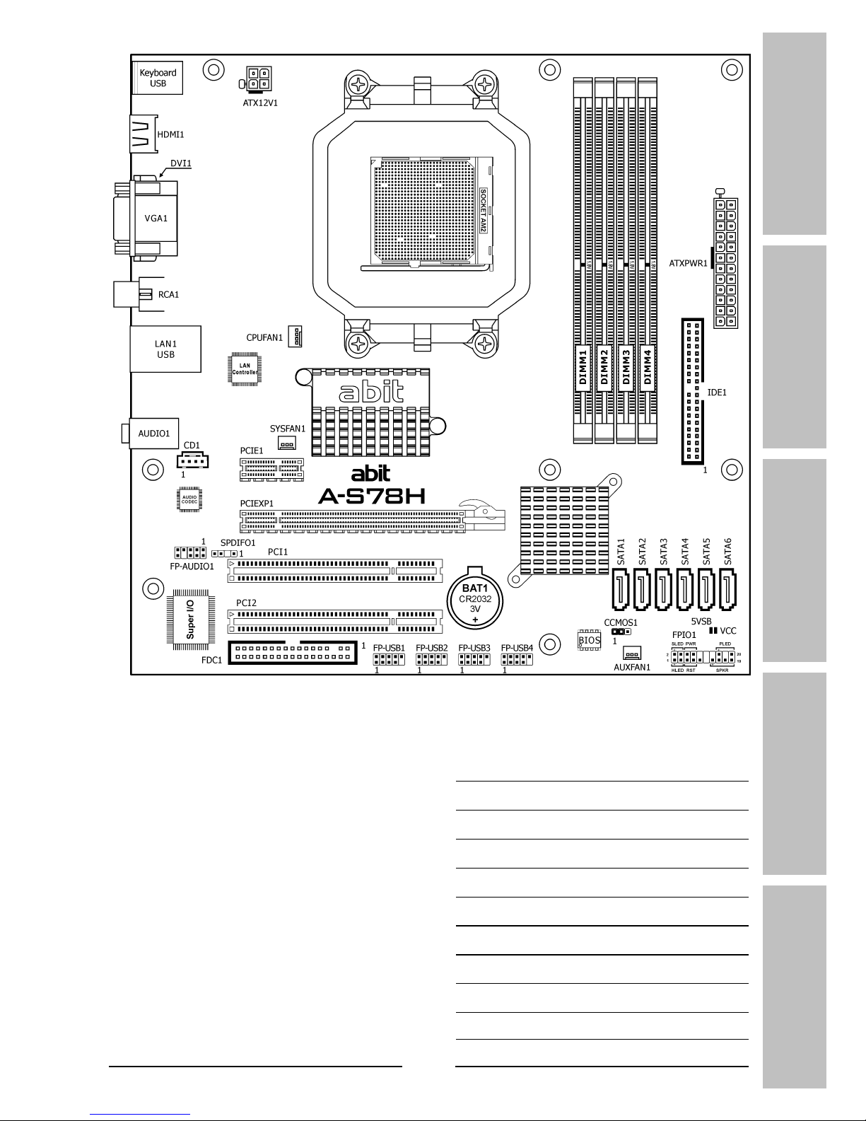
1.2 Motherboard Layout ..................................................................... 1-2
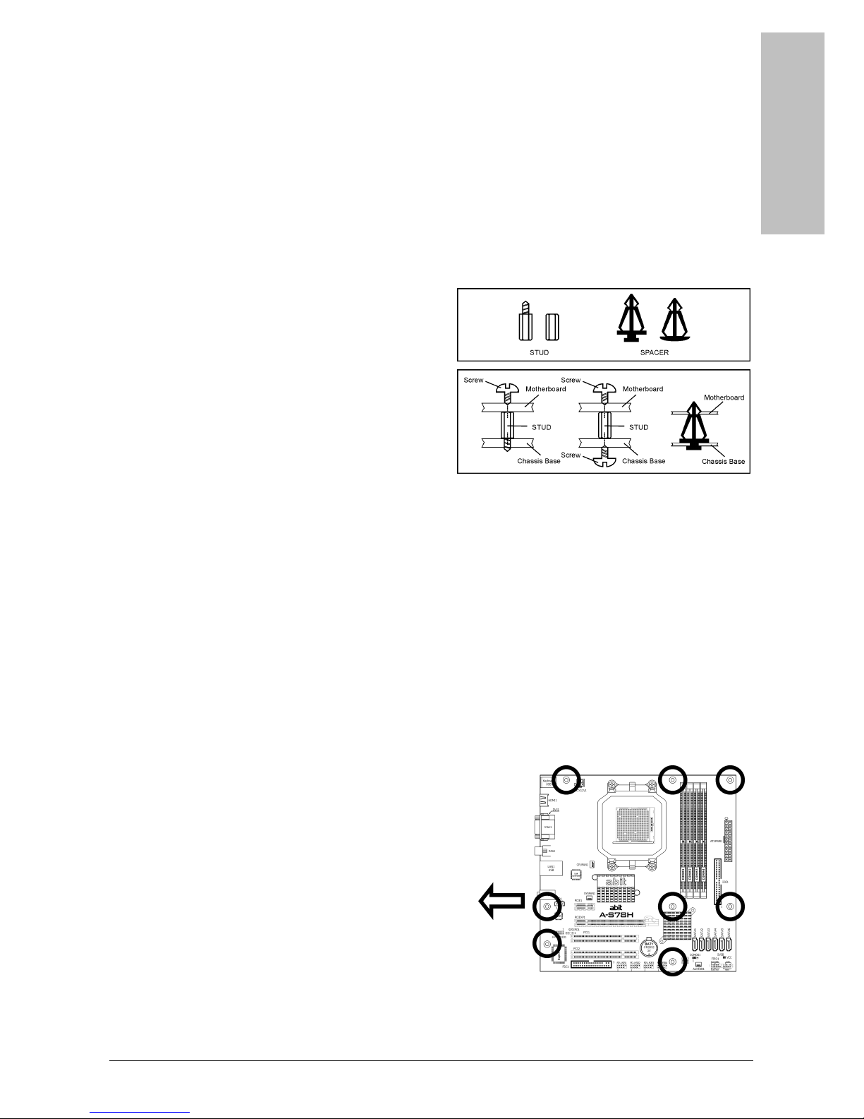
1.3 Choosing a Computer Chassis ....................................................... 1-3
1.4 Installing Motherboard ................................................................. 1-3
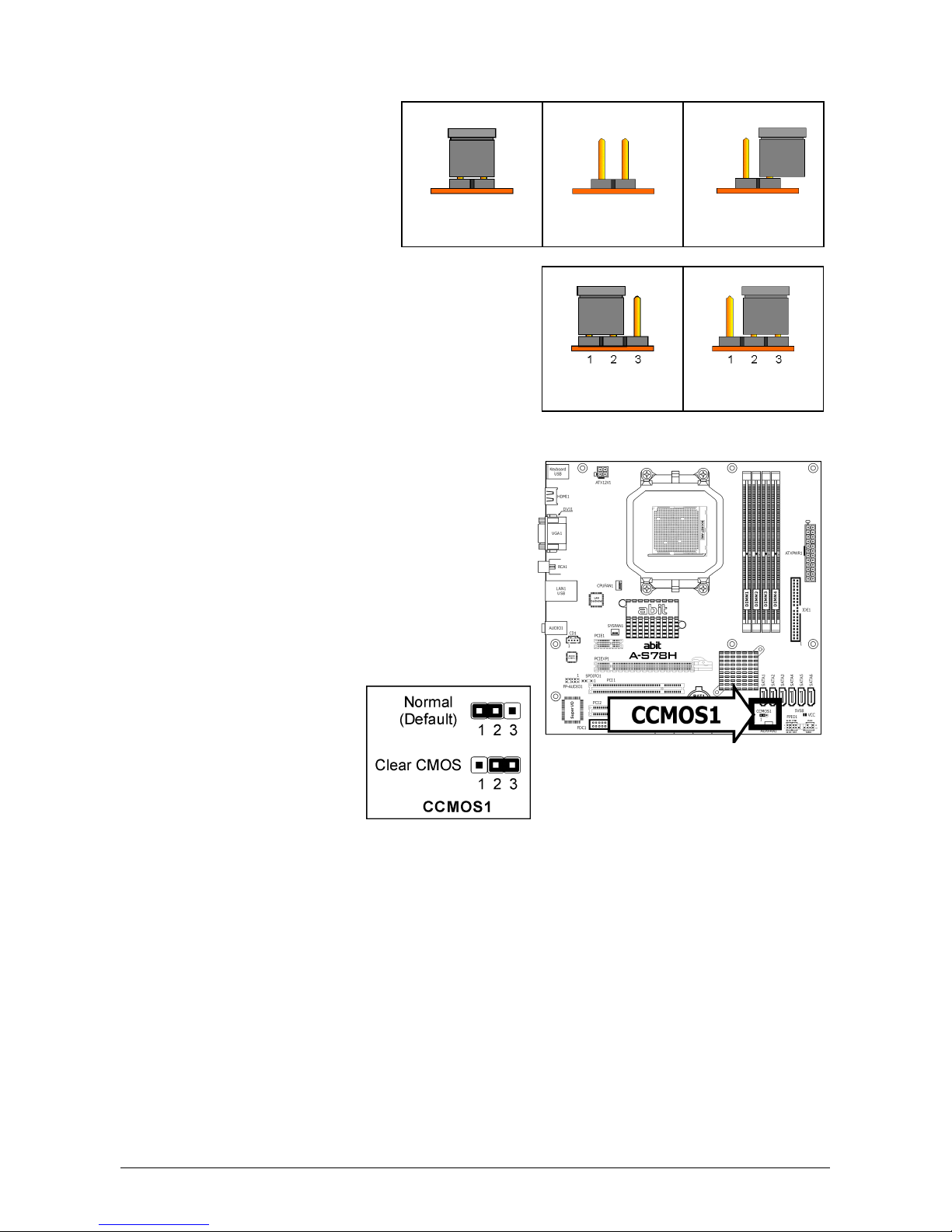
1.5 Checking Jumper Settings............................................................. 1-4
1.5.1 CMOS Memory Clearing Header and Backup Battery .............. 1-4
1.6 Connecting Chassis Components ................................................... 1-6
1.6.1 Power Connectors ............................................................... 1-6
1.6.2 Front Panel Switches & Indicators Headers ........................... 1-7
1.6.3 FAN Power Connectors ........................................................ 1-8
1.7 Installing Hardware...................................................................... 1-9
1.7.1 CPU Socket ......................................................................... 1-9
1.7.2 DDR2 Memory Slots........................................................... 1-11
1.8 Connecting Peripheral Devices .................................................... 1-12
1.8.1 Floppy and IDE Disk Drive Connectors ................................ 1-12
1.8.2 Serial ATA Connectors ....................................................... 1-13
1.8.3 Additional USB 2.0 Port Headers......................................... 1-14
1.8.4 Internal Audio Connectors.................................................. 1-14
1.8.5 Front Panel Audio Connection Header ................................. 1-15
1.8.6 S/PDIF Output Connection Header...................................... 1-15
1.8.7 PCI and PCI Express X16, X1 Slots ..................................... 1-16
1.9 Onboard Indicators .................................................................... 1-17
1.9.1 Power Source Indicators .................................................... 1-17
1.10 Connecting Rear Panel I/O Devices ........................................... 1-18
2. BIOS Setup....................................................................... 2-1
2.1 SoftMenu Setup ........................................................................... 2-2
2.2 Standard CMOS Features.............................................................. 2-3
2.3 Advanced BIOS Features .............................................................. 2-6
2.4 Advanced Chipset Features........................................................... 2-8
2.5 Integrated Peripherals................................................................ 2-11
2.6 Power Management Setup .......................................................... 2-14
2.7 PnP/PCI Configurations .............................................................. 2-16
2.8 PC Health Status ........................................................................ 2-17
2.9 Load Fail-Safe Defaults............................................................... 2-18
2.10 Load Optimized Defaults........................................................... 2-18
2.11 Set Password ........................................................................... 2-18
2.12 Save & Exit Setup..................................................................... 2-18
2.13 Exit Without Saving .................................................................. 2-18
3. Driver & Utility ................................................................. 3-1
3.1 CD-ROM AUTORUN ...................................................................... 3-1
3.2 Q-Install ...................................................................................... 3-2
3.3 Microsoft.NET Framework............................................................. 3-2
3.4 AMD South Bridge Driver .............................................................. 3-3
3.5 AMD VGA Driver........................................................................... 3-3

iv A-S78H
3.6 Marvell LAN Driver ....................................................................... 3-3
3.7 Realtek Audio Driver (AMD HDMI Driver)....................................... 3-4
3.8 AMD RAID Driver ......................................................................... 3-5
3.9 Cool’n’Quiet Driver ....................................................................... 3-5
3.10 USB 2.0 Driver ........................................................................... 3-6
3.11 Acrobat Reader 8.0 .................................................................... 3-7
3.12 AMD RAID Utility ........................................................................ 3-7
3.13 abitEQ (The Hardware Doctor Utility) .......................................... 3-8
3.14 FlashMenu (BIOS Update Utility) ................................................. 3-9
3.15 SATA RAID Driver (for Windows Vista) ...................................... 3-10
3.16 SATA RAID Driver (for Windows XP, 2003, or 2000) ................... 3-10
4. Multilingual Quick Installation Guide .............................. 4-1
4.1 Français//Guide d'Installation Rapide............................................. 4-1
4.2 Deutsch//Kurze Installationsanleitung............................................ 4-2
4.3 Italiano//Guida all’installazione rapida ........................................... 4-3
4.4 Español//Guía rápida de instalación............................................... 4-4
4.5 Português//Guia de instalação rápida ............................................ 4-5
4.6 Русский//Краткое руководство по установке .............................. 4-6
4.7 Eesti//Kiirpaigaldusjuhend ............................................................ 4-7
4.8 Latviski//Ātrās instalēšanas instrukcija........................................... 4-8
4.9 Lietuvių//Trumpas instaliavimo vadovas ........................................ 4-9
4.10 Polski//Instrukcja szybkiej instalacji........................................... 4-10
4.11 Magyar//Gyorstelepítési útmutató.............................................. 4-11
4.12 Türkçe//HızlıKurulum Kılavuzu.................................................. 4-12
4.13 اللغة العربية//دليل التركيب السريع....................... 4-13
4.14 فارسی// راﻩنمای نصب سریع............................................... 4-14
4.15 日本語//クイックインストールガイド ...................................... 4-15
4.16 한국어//빠른 설치 가이드 ....................................................... 4-16
4.17 Bahasa Malaysia//Panduan Pemasangan Ringkas ....................... 4-17
4.18 ไทย//คู่มือการติดตั้งอย่างย่อ ........................................................ 4-18
4.19 繁體中文................................................................................. 4-19
4.19.1 規格............................................................................... 4-19
4.19.2 快速安裝略說.................................................................. 4-20
4.20 简体中文................................................................................. 4-21
4.20.1 规格 ............................................................................... 4-21
4.20.2 快速安装略说.................................................................. 4-22
5. Appendix .......................................................................... 5-1
5.1 ATI Hybrid CrossFireX Technology................................................. 5-1
5.1.1 Setup Requirements ............................................................ 5-1
5.1.2 Desktop Performance .......................................................... 5-1
5.1.3 Setup Procedures ................................................................ 5-1
5.2 Troubleshooting (How to Get Technical Support?).......................... 5-3
5.2.1 Q & A ................................................................................. 5-3
5.2.2 Technical Support Form....................................................... 5-6
5.2.3 Contact Information............................................................. 5-7

Hardware Setup
A-S78H 1-1
1. Hardware Setup
1.1 Specifications
CPU
• Supports Socket AMD AM2+/AM2
Processor using Hyper Transport™
Technology up to 5200MT/s*
*
AM2+ running HT3.0 5200MT/s
*
AM2 running HT1.0 2000MT/s
• Supports AMD CPU Cool ‘n’ Quiet
Technology
Chipset
• AMD 780G Chipset with ATI Radeon HD
3200 Graphics (RS780) / SB700
Memory
• 4x 240-pin DIMM slots support
maximum memory capacity up to 8GB
• Supports Dual Channel DDR2
1066*/800/667 Un-buffered
ECC/Non-ECC memory
*
DDR2 1066 is supported by AM2+ CPU only.
Graphics
• ATI RV610-based Graphics Engine
• ATI Hybrid CrossFireX Technology
• ATI UVD (Unified Video Decoder)
hardware for H.264, VC-1, and MPEG-2
decode
• Two independent display controllers for
CRT and HDMI/DVI interfaces
LAN
• Onboard Gigabit LAN
Audio
• Onboard 5.1-CH HD Audio CODEC
Serial ATA
• 6x SATA 3Gb/s supports AHCI and RAID
0/1/0+1
Expansion Slots
• 1x PCI-E X16 slot (PCI Express 2.0)
• 1x PCI-E X1 slot
• 2x PCI slots
Internal I/O Connectors
• 1x Floppy port
• 1x Ultra ATA 133 IDE connector
• 6x SATA 3Gb/s connectors
• 4x USB 2.0 headers
• 1x FP-Audio header
• 1x CD-In connector
• 1x S/PDIF Out Header
Rear Panel I/O
• 1x PS/2 Keyboard connector
• 1x HDMI connector
• 1x D-Sub connector
• 1x DVI connector
• 1x RCA Out connector
• 1x RJ-45 LAN connector
• 4x USB 2.0 connectors
• 1x 5.1-CH HD Audio connector
abit Engineered
• abit Softmenu™Technology
• abit EQ Technology
RoHS
• 100% Lead-free process and RoHS
compliant
Miscellaneous
• Micro ATX form factor (244mm x
244mm)
• Windows Vista Premium HW Ready
※ Specifications and information contained herein are subject to change without
notice.

1-2 A-S78H
1.2 Motherboard Layout

Hardware Setup
A-S78H 1-3
1.3 Choosing a Computer Chassis
• Choose a chassis big enough to install this motherboard.
• As some features for this motherboard are implemented by cabling connectors on the
motherboard to indicators and switches or buttons on the chassis, make sure your chassis
supports all the features required.
• If there is a possibility of adopting some more hard drives, make sure your chassis has
sufficient power and space for them.
• Most chassis have alternatives for I/O shield located at the rear panel. Make sure the I/O
shield of the chassis matches the I/O port configuration of this motherboard. You can find
an I/O shield specifically designed for this motherboard in its package.
1.4 Installing Motherboard
Most computer chassis have a base with many
mounting holes to allow the motherboard to be
securely attached, and at the same time, prevent
the system from short circuits. There are two
ways to attach the motherboard to the chassis
base: (1) with studs, or (2) with spacers.
Basically, the best way to attach the board is
with studs. Only if you are unable to do this
should you attach the board with spacers. Line up the holes on the board with the mounting
holes on the chassis. If the holes line up and there are screw holes, you can attach the board
with studs. If the holes line up and there are only slots, you can only attach with spacers. Take
the tip of the spacers and insert them into the slots. After doing this to all the slots, you can
slide the board into position aligned with slots. After the board has been positioned, check to
make sure everything is OK before putting the chassis back on.
※ Always power off the computer and unplug the AC power cord before adding or
removing any peripheral or component. Failing to so may cause severe damage
to your motherboard and/or peripherals. Plug in the AC power cord only after
you have carefully checked everything.
To install this motherboard:
1. Locate all the screw holes on the
motherboard and the chassis base.
2. Place all the studs or spacers needed on
the chassis base and have them tightened.
3. Face the motherboard’s I/O ports toward
the chassis’s rear panel.
4. Line up all the motherboard’s screw holes
with those studs or spacers on the chassis.
5. Install the motherboard with screws and
have them tightened.
※ To prevent shorting the PCB circuit,
please REMOVE the metal studs or
spacers if they are already fastened
on the chassis base and are without
mounting-holes on the motherboard
to align with.
Face the chassis’s rear panel.

1-4 A-S78H
1.5 Checking Jumper Settings
• For a 2-pin jumper, plug the
jumper cap on both pins will
make it CLOSE (SHORT).
Remove the jumper cap, or
plug it on either pin
(reserved for future use) will
leave it at OPEN position.
SHORT OPEN
OPEN
• For 3-pin jumper, pin 1~2 or pin 2~3 can be
shorted by plugging the jumper cap in.
Pin 1~2 SHORT
Pin 2~3 SHORT
1.5.1 CMOS Memory Clearing Header and Backup Battery
The time to clear the CMOS memory occurs when (a)
the CMOS data becomes corrupted, (b) you forgot the
supervisor or user password preset in the BIOS menu,
(c) you are unable to boot-up the system because the
CPU ratio/clock was incorrectly set in the BIOS menu,
or (d) whenever there is modification on the CPU or
memory modules.
This header uses a jumper cap to clear the CMOS
memory and have it reconfigured to the default values
stored in BIOS.
• Pins 1 and 2 shorted
(Default): Normal
operation.
• Pins 2 and 3 shorted:
Clear CMOS memory.
To clear the CMOS memory and load in the default values:
1. Power off the system.
2. Set pin 2 and pin 3 shorted by the jumper cap. Wait for a few seconds. Set the jumper
cap back to its default settings --- pin 1 and pin 2 shorted.
3. Power on the system.
4. For incorrect CPU ratio/clock settings in the BIOS, press <Del> key to enter the BIOS
setup menu right after powering on system.
5. Set the CPU operating speed back to its default or an appropriate value.
6. Save and exit the BIOS setup menu.

Hardware Setup
A-S78H 1-5
CMOS Backup Battery:
An onboard battery saves the CMOS memory to keep the BIOS information stays on even after
disconnected your system with power source. Nevertheless, this backup battery exhausts after
some five years. Once the error message like “CMOS BATTERY HAS FAILED” or “CMOS
checksum error” displays on monitor, this backup battery is no longer functional and has to
be renewed.
To renew the backup battery:
1. Power off the system and disconnect with AC power source.
2. Remove the exhausted battery.
3. Insert a new CR2032 or equivalent battery. Pay attention to its polarity. The “+” side is its
positive polarity.
4. Connect AC power source and power on the system.
5. Enter the BIOS setup menu. Reconfigure the setup parameters if necessary.
CAUTION:
※ Danger of explosion may arise if the battery is incorrectly renewed.
※ Renew only with the same or equivalent type recommended by the battery
manufacturer.
※ Dispose of used batteries according to the battery manufacturer’s instructions.

1-6 A-S78H
1.6 Connecting Chassis Components
1.6.1 Power Connectors
For a fully configured system, we recommend that
you use a power supply of ATX12V 2.0 (or newer)
specification compliant and of providing minimum
400W power output capability.
※ The following motherboard photos are
served for DEMO only, and may not be
the same type or model as the one
described in this user’s manual.
[ATXPWR1]: 24-pin power connector
You may connect either a 20-pin (ATX12V
1.3) or 24-pin (ATX12V 2.0) power source.
However, it is recommended to connect the
24-pin ATX12V power source to meet the
240VA protection limits.
Plugged from a 24-pin
ATX12V power.
Plugged from a 20-pin
ATX12V power.
[ATX12V1]: 8-pin power connector
This connector supplies +12V power to CPU.
You may connect either a 4-pin ATX12V or
an 8-pin EPS12V power source. However, it
is recommended to connect the 8-pin
EPS12V power source to meet the 240VA
protection limits.
Plugged from a 4-pin
ATX12V power.
Plugged from an 8-pin
EPS12V power.

Hardware Setup
A-S78H 1-7
1.6.2 Front Panel Switches & Indicators Headers
This header is used for connecting switches and LED indicators on the chassis front panel.
Watch the power LED pin position and orientation. The mark “+” align to the pin in the figure
below stands for positive polarity for the LED connection. Please pay attention when connecting
these headers. A wrong orientation will only result in the LED not lighting, but a wrong
connection of the switches could cause system malfunction.
• HLED (Pin 1, 3):
Connects to the HDD LED cable of chassis front panel.
• RST (Pin 5, 7):
Connects to the Reset Switch cable of chassis front panel.
• SPKR (Pin 13, 15, 17, 19):
Connects to the System Speaker cable of chassis.
• SLED (Pin 2, 4):
Connects to the Suspend LED cable (if there is one) of chassis front panel.
• PWR (Pin 6, 8):
Connects to the Power Switch cable of chassis front panel.
• PLED (Pin 16, 18, 20):
Connects to the Power LED cable of chassis front panel.

1-8 A-S78H
1.6.3 FAN Power Connectors
These connectors each provide power to the cooling fans installed in your system.
• CPUFAN1: CPU Fan Power Connector
• SYSFAN1: System Fan Power Connector
• AUXFAN1: Auxiliary Fan Power Connector
※ These fan connectors are not jumpers. DO NOT place jumper caps on these
connectors.
※ Either a
3-pin
or
4-pin
CPU cooling fan connected to the “CPUFAN1” connector
is still capable of having its fan speed controlled. Please refer to the BIOS setup
route: “PC Health Status” “CPU FANEQ Control” “CPU FAN Type” to select
the one of your own.

Hardware Setup
A-S78H 1-9
1.7 Installing Hardware
※ DO NOT scratch the motherboard when installing hardware. An accidentally
scratch of a tiny surface-mount component may seriously damage the
motherboard.
1.7.1 CPU Socket
※ DO NOT touch or bend the delicate pins on the CPU whenever you are holding it.
The installation procedures vary with different types of CPU fan-and-heatsink assembly. The
one shown here is served for DEMO only. For detailed information on how to install the one
you bought, refer to its installation guidelines.
1. Pull out the socket lever away from the
socket and fully lift it up over 90-degree
angle.
Locate and align the triangle mark with
both the CPU and the socket body.
Vertically place the CPU with its pin-side
down into the socket.
Be careful to insert the CPU into the
socket. The CPU only fits in one
orientation with the socket. DO NOT
force the CPU into the socket.
2. After placing the CPU into position, push
the socket lever down into its locked
position to secure the CPU. The lever
clicks when it’s locked into position.
3. The heatsink for CPU may have thermal
interface material attached to its
bottom. If not, applying a few squeeze
of thermal paste to the CPU die will help
to increase the contact.

1-10 A-S78H
4. Place the heatsink and fan assembly
onto the retention frame. Match the
heatsink clip with the socket
mounting-lug. Hook the spring clip to
the mounting-lug.
5. On the other side, push the retention
clip straight down to lock into the plastic
lug on the retention frame.
6. Connect the CPU cooling fan power
cable to the [CPUFAN1] connector on
this motherboard.
※ Either a
3-pin
or
4-pin
CPU cooling
fan connected to the [CPUFAN1]
connector is still capable of having
its fan speed controlled. Please refer
to the BIOS setup route: “PC Health
Status” “CPU FANEQ Control”
“CPU FAN Type” to select the one of
your own.
Also, please watch out for the
orientation when inserting 3-Pin
plug into this 4-Pin fan connector.
※ The motherboard in this illustration is served for DEMO only, may not be the
same type or model as the one described in this user’s manual.
※ A higher fan speed will be helpful for better airflow and heat-dissipation.
Nevertheless, stay alert to not touch any heatsink since a high temperature
generated by the working system is still possible.

Hardware Setup
A-S78H 1-11
1.7.2 DDR2 Memory Slots
To reach the performance of Dual Channel DDR2, the following rules must be obeyed:
• For a 2-DIMM dual-channel installation:
Populate DIMM modules of the same type and size on slots [DIMM1]+[DIMM2], or slots
[DIMM3]+[DIMM4].
• For a 4-DIMM dual-channel installation:
Populate 2 DIMM modules of the same type and size on slots [DIMM1]+[DIMM2], and
another 2 DIMM modules of the same type and size on slots [DIMM3]+[DIMM4].
※ [DIMM1] and [DIMM2] slots are made of the same color.
[DIMM3] and [DIMM4] are made of another same color.
Usually there is no hardware or BIOS setup requires after adding or removing memory modules,
but you will have to clear the CMOS memory first if any memory module related problem
occurs.
To install system memory:
1. Power off the computer and unplug the
AC power cord before installing or
removing memory modules.
2. Locate the DIMM slot on the board.
3. Hold two edges of the DIMM module
carefully, keep away from touching its
connectors.
4. Align the notch key on the module with the rib on the slot.
5. Firmly press the module into the slots until the ejector tabs at both sides of the slot
automatically snap into the mounting notch. Do not force the DIMM module in with extra
force as the DIMM module only fits in one direction.
6. To remove the DIMM modules, push the two ejector tabs on the slot outward
simultaneously, and then pull out the DIMM module.
※ Static electricity can damage the electronic components of the computer or
optional boards. Before starting these procedures, ensure that you are
discharged of static electricity by touching a grounded metal object briefly.

1-12 A-S78H
1.8 Connecting Peripheral Devices
1.8.1 Floppy and IDE Disk Drive Connectors
Connect your floppy drive to the [FDC1] port by a floppy cable.
※ Check the pin-1 orientation before connecting. Make sure to align with the
pin-1 mark on both the [FDC1] port and floppy drive connector.
Connect your IDE drive(s) to [IDE1] port by an IDE
cable.
Each of the IDE port connects up to two IDE drives
by an IDE cable. Connect the single end of the
cable’s longer length to the [IDE1] port, and then
connect the other two ends to your IDE drives.
※ Make sure to configure the “Master” and “Slave” relation before connecting
two drives by one cable.
※ Check the pin-1 orientation before connecting. Make sure to align with the
pin-1 mark on both the [IDE1] port and IDE drive connector.

Hardware Setup
A-S78H 1-13
1.8.2 Serial ATA Connectors
Each SATA connector serves as one single channel to connect one SATA device by SATA cable.
To connect SATA device:
1. Attach either end of the signal cable
to the SATA connector on
motherboard. Attach the other end to
the SATA device.
2. Attach the SATA power cable to the
SATA device and connect the other
end from the power supply.
※ The motherboard in this photo is served for DEMO only, and may not be the
same type or model as the one described in this user’s manual.

1-14 A-S78H
1.8.3 Additional USB 2.0 Port Headers
Each header supports 2x additional USB 2.0 ports by connecting bracket or cable to the rear I/O
panel or the front-mounted USB ports of your chassis.
Pin Pin Assignment Pin Pin Assignment
1 VCC 2 VCC
3 Data0 - 4 Data1 -
5 Data0 + 6 Data1 +
7 Ground 8 Ground
10 NC
※ Make sure the connecting cable bears the same pin assignment.
1.8.4 Internal Audio Connectors
This connector connects to the audio output of internal CD-ROM drive or add-on card.

Hardware Setup
A-S78H 1-15
1.8.5 Front Panel Audio Connection Header
This header provides the front panel connection for HD (High Definition)
Audio, yet for AC’97 Audio CODEC connection, you must carefully check the
pin assignment before connecting from the front panel module. An incorrect
connection may cause malfunction or even damage the motherboard.
※ Please do not connect the “Ground” cable or “USB VCC” cable
from the front panel module to the Pin 4 “AVCC” of this
header.
Pin Pin Assignment
(HD AUDIO) Pin Pin Assignment
(AC’97 AUDIO)
1 MIC2 L 1 MIC In
2 AGND 2 GND
3 MIC2 R 3 MIC Power
4 AVCC 4NC
5 FRO-R 5 Line Out (R)
6 MIC2_JD 6 NC
7 F_IO_SEN 7 NC
9 FRO-L 9 Line Out (L)
10 LINE2_JD 10 NC
※ To configure AC’97 front panel audio connection, please enter the BIOS setup
menu and select the option [AC97] via route: “Integrated Peripherals”
“FP-Audio”.
1.8.6 S/PDIF Output Connection Header
This header provides the S/PDIF output connection to your add-on HDMI VGA card.
(Available
for A-N78HD only)
Pin Pin Assignment
1 VCC (5V)
2 x
3 S/PDIF Out
4 Ground

1-16 A-S78H
1.8.7 PCI and PCI Express X16, X1 Slots
Install PCI Express X16 graphics card into slot “PCIEXP1”.
Install PCI Express X1 card into slot “PCIE1”.
Install PCI cards into slots “PCI1”, and/or “PCI2”.
Table of contents
Other Abit Motherboard manuals
Popular Motherboard manuals by other brands

Microchip Technology
Microchip Technology TC64X user guide

Quantum Design
Quantum Design PlatiniX 1E manual

mikroElektronika
mikroElektronika EasyMx PRO v7 user guide

SOYO
SOYO 82430 TX User's guide & technical reference

Synway
Synway DST Series Configuration manual

Texas Instruments
Texas Instruments UCC28880EVM-616 user guide