ABLE VEGAPULS 62 Installation and operating instructions

Installation & Maintenance Instructions
VEGAPULS 62
4 … 20 mA/HART - two-wire
Radar sensor for continuous level measurement of liquids
Reading Office
Cutbush Park, Danehill, Lower Earley,
Reading, Berkshire. RG6 4UT. UK.
Tel: +44 (0)118 9311188
Email: [email protected]
Aberdeen Office
Unit 6 Airside Business Park, Kirkhill Industrial Estate,
Dyce, Aberdeen. AB21 0GT. UK.
Tel: +44 (0)1224 725999
Email: [email protected]
Internet: www.able.co.uk
e-procurement: www.247able.com
Registered in England No: 01851002
VAT No: GB 417 2481 61

2
Quick start
VEGAPULS 62 • 4 … 20 mA/HART - two-wire
36503-EN-121011
Quick start
The quick start enables a quick setup with many applications. You
can nd further information in the respective chapters of the operating
instructions manual.
1. Distance from the vessel wall > 200 mm, the antenna should
protrude > 10 mm into the vessel
ca. 10 mm
> 200 mm
(7.87
")
Fig. 1: Distance of the antenna to the vessel wall/vessel ceiling
2. Note min. socket diameter depending on the socket length
For further information see chapter "Mounting".
1. Make sure that the power supply corresponds to the specica-
tions on the type label.
2. Connect the instrument according to the following illustration
5
12
+
( ) (-)
678
4...20mA
2
3
4
1
Fig. 2: Electronics and connection compartment, single chamber housing
1 Voltage supply, signal output
2 For indicating and adjustment module or interface adapter
3 For external indicating and adjustment unit
4 Ground terminal for connection of the cable screen
For further information see chapter "Connecting to power supply".
1. Go via the indicating and adjustment module to the menu "Setup".
2. In the menu item "Medium"you select the medium of your applica-
tion, for example "Aqueous solution".
Mounting
Connect electrically
Set parameters

3
Quick start
VEGAPULS 62 • 4 … 20 mA/HART - two-wire
36503-EN-121011
3. Select in the menu item "Application" the vessel, the application
and the vessel form, for example, storage tank.
4. Carry out the adjustment in the menu items "Min. adjustment" and
"Max. adjustment".
The radar sensor measures the distance from the sensor to the
product surface. For indication of the real level, an allocation of the
measured distance to the percentage height must be carried out.
100%
0%
0,5 m
(19.68
")
5 m
(196.9
")
2
1
Fig. 3: Parameter adjustment example min./max. adjustment
1 Min. level = max. meas. distance
2 Max. level = min. meas. distance
For this adjustment, the distance is entered with full and virtually
empty vessel. If these values are not known, an adjustment with
distances, for example, of 10 % and 90 % is also possible. Starting
point for these distance specications is always the seal surface of
the thread or ange.
1. In the menu "Additional settings", menu item "Damping" you have
to adjust the requested damping of the output signal.
2. Select the output characteristics in the menu item "Current out-
put".
The quick start is then nished. For further information see chapter
"Parameter adjustment".
Parameterization example
Further steps

4
Contents
VEGAPULS 62 • 4 … 20 mA/HART - two-wire
36503-EN-121011
Contents
1 About this document
1.1 Function ............................................................................. 6
1.2 Target group ....................................................................... 6
1.3 Symbolism used ................................................................. 6
2 For your safety
2.1 Authorised personnel ......................................................... 7
2.2 Appropriate use .................................................................. 7
2.3 Warning about incorrect use ............................................... 7
2.4 General safety instructions ................................................. 7
2.5 CE conformity ..................................................................... 8
2.6 NAMUR recommendations ................................................ 8
2.7 Radio license for Europe .................................................... 8
2.8 Radio license for USA/Canada ........................................... 8
2.9 Environmental instructions ................................................. 9
3 Product description
3.1 Conguration .................................................................... 10
3.2 Principle of operation ........................................................ 11
3.3 Packaging, transport and storage ..................................... 12
3.4 Accessories and replacement parts ................................. 12
4 Mounting
4.1 General instructions ......................................................... 14
4.2 Mounting preparations - Horn antenna ............................. 14
4.3 Mounting preparations - Parabolic antenna ...................... 15
4.4 Instructions for installation ................................................ 16
5 Connecting to power supply
5.1 Preparing the connection ................................................. 27
5.2 Connecting ....................................................................... 28
5.3 Wiring plan, single chamber housing ................................ 29
5.4 Wiring plan, double chamber housing .............................. 30
5.5 Wiring plan, Ex-d double chamber housing ...................... 31
5.6 Wiring plan - version IP 66/IP 68, 1 bar ............................. 32
5.7 Switch-on phase ............................................................... 32
6 Set up with the indicating and adjustment module
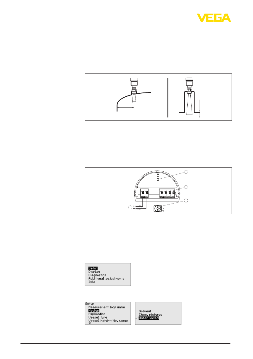
6.1 Insert indicating and adjustment module .......................... 34
6.2 Adjustment system ........................................................... 35
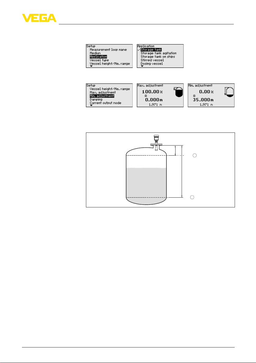
6.3 Parameter adjustment ...................................................... 36
6.4 Saving the parameter adjustment data ............................. 49
7 Setup with PACTware
7.1 Connect the PC ................................................................ 50
7.2 Parameter adjustment with PACTware .............................. 51
7.3 Saving the parameter adjustment data ............................. 52
8 Set up with other systems
8.1 DD adjustment programs ................................................. 53
8.2 Communicator 375, 475 ................................................... 53
9 Diagnosis, Asset Management and service

5
Contents
VEGAPULS 62 • 4 … 20 mA/HART - two-wire
36503-EN-121011
9.1 Maintenance .................................................................... 54
9.2 Diagnosis memory ........................................................... 54
9.3 Asset Management function ............................................. 55
9.4 Rectify faults ..................................................................... 58
9.5 Exchanging the electronics module .................................. 62
9.6 Software update ............................................................... 62
9.7 How to proceed in case of repair ...................................... 63
10 Dismounting
10.1 Dismounting steps ............................................................ 64
10.2 Disposal ........................................................................... 64
11 Supplement
11.1 Technical data .................................................................. 65
11.2 Dimensions ...................................................................... 73
Safety instructions for Ex areas
Please note the Ex-specic safety information for installation and op-
eration in Ex areas. These safety instructions are part of the operating
instructions manual and come with the Ex-approved instruments.
Editing status: 2012-09-27

6
1 About this document
VEGAPULS 62 • 4 … 20 mA/HART - two-wire
36503-EN-121011
1 About this document
1.1 Function
This operating instructions manual provides all the information you
need for mounting, connection and setup as well as important instruc-
tions for maintenance and fault rectication. Please read this informa-
tion before putting the instrument into operation and keep this manual
accessible in the immediate vicinity of the device.
1.2 Target group
This operating instructions manual is directed to trained qualied
personnel. The contents of this manual should be made available to
these personnel and put into practice by them.
1.3 Symbolism used
Information, tip, note
This symbol indicates helpful additional information.
Caution: If this warning is ignored, faults or malfunctions can result.
Warning: If this warning is ignored, injury to persons and/or serious
damage to the instrument can result.
Danger: If this warning is ignored, serious injury to persons and/or
destruction of the instrument can result.
Ex applications
This symbol indicates special instructions for Ex applications.
• List
The dot set in front indicates a list with no implied sequence.
→ Action
This arrow indicates a single action.
1 Sequence
Numbers set in front indicate successive steps in a procedure.
Battery disposal
This symbol indicates special information about the disposal of bat-
teries and accumulators.

7
2 For your safety
VEGAPULS 62 • 4 … 20 mA/HART - two-wire
36503-EN-121011
2 For your safety
2.1 Authorised personnel
All operations described in this operating instructions manual must
be carried out only by trained specialist personnel authorised by the
plant operator.
During work on and with the device the required personal protective
equipment must always be worn.
2.2 Appropriate use
VEGAPULS 62 is a sensor for continuous level measurement.
You can nd detailed information on the application range in chapter
"Product description".
Operational reliability is ensured only if the instrument is properly
used according to the specications in the operating instructions
manual as well as possible supplementary instructions.
2.3 Warning about incorrect use
Inappropriate or incorrect use of the instrument can give rise to
application-specic hazards, e.g. vessel overll or damage to system
components through incorrect mounting or adjustment.
2.4 General safety instructions
This is a state-of-the-art instrument complying with all prevailing
regulations and guidelines. The instrument must only be operated in a
technically awless and reliable condition. The operator is responsible
for the trouble-free operation of the instrument.
During the entire duration of use, the user is obliged to determine the
compliance of the necessary occupational safety measures with the
current valid rules and regulations and also take note of new regula-
tions.
The safety instructions in this operating instructions manual, the na-
tional installation standards as well as the valid safety regulations and
accident prevention rules must be observed by the user.
For safety and warranty reasons, any invasive work on the device
beyond that described in the operating instructions manual may be
carried out only by personnel authorised by the manufacturer. Arbi-
trary conversions or modications are explicitly forbidden.
The safety approval markings and safety tips on the device must also
be observed.
Depending on the instrument version, the emitting frequencies are in
the C or K band range. The low emitting frequencies are far below the
internationally approved limit values. When used correctly, there is no
danger to health.

8
2 For your safety
VEGAPULS 62 • 4 … 20 mA/HART - two-wire
36503-EN-121011
2.5 CE conformity
The device fullls the legal requirements of the applicable EC guide-
lines. By axing the CE marking, we conrm successful testing of the
product.
You can nd the conformity certicate in the download section of our
homepage.
Only with Ex-d-ia version
The instrument is designed for use in an industrial environment.
Nevertheless, electromagnetic interference from electrical conductors
and radiated emissions must be taken into account, as is usual with a
class A instrument according to EN 61326-1. If the instrument is used
in a dierent environment, its electromagnetic compatibility with other
devices must be ensured by suitable measures.
2.6 NAMUR recommendations
NAMUR is the automation technology user association in the process
industry in Germany. The published NAMUR recommendations are
accepted as the standard in eld instrumentation.
The device fullls the requirements of the following NAMUR recom-
mendations:
• NE 21 – Electromagnetic compatibility of equipment
• NE 43 – Signal level for malfunction information from measuring
transducers
• NE 53 – Compatibility of eld devices and indicating/adjustment
components
• NE 107 - Self-monitoring and diagnosis of eld devices
For further information see www.namur.de.
2.7 Radio license for Europe
The instrument is approved according to EN 302372-1/2 (2006-04)
for use in closed vessels.
2.8 Radio license for USA/Canada
The instrument is in conformity with part 15 of the FCC regulations.
Take note of the following two regulations:
• The instrument must not cause any interfering emissions
• The device must be insensitive to interfering immissions, including
those that may cause undesirable operating conditions
Modications not expressly approved by the manufacturer will lead to
expiry of the operating licence according to FCC/IC.
The instrument is in conformity with RSS-210 of the IC regulations.
The instrument may only be used in closed vessels made of metal,
concrete, or bre-reinforced plastic.

9
2 For your safety
VEGAPULS 62 • 4 … 20 mA/HART - two-wire
36503-EN-121011
2.9 Environmental instructions
Protection of the environment is one of our most important duties.
That is why we have introduced an environment management system
with the goal of continuously improving company environmental pro-
tection. The environment management system is certied according
to DIN EN ISO 14001.
Please help us full this obligation by observing the environmental
instructions in this manual:
• Chapter "Packaging, transport and storage"
• Chapter "Disposal"

10
3 Product description
VEGAPULS 62 • 4 … 20 mA/HART - two-wire
36503-EN-121011
3 Product description
3.1 Conguration
The type label contains the most important data for identication and
use of the instrument:
2
1
13
14
15
16
12
11
5
3
6
4
7
8
9
10
Fig. 4: Layout of the type label (example)
1 Instrument type
2 Product code
3 Approvals
4 Power supply and signal output, electronics
5 Protection rating
6 Measuring range
7 Process and ambient temperature, process pressure
8 Material, wetted parts
9 Hardware and software version
10 Order number
11 Serial number of the instrument
12 Symbol of the device protection class
13 ID numbers, instrument documentation
14 Note to observe the instrument documentation
15 NotiedauthorityforCEmarking
16 Approval directive
With the serial number of the instrument on the type label you have
access to the following data on our homepage:
• Article number of the instrument (HTML)
• Delivery date (HTML)
• Order-specic instrument features (HTML)
• Operating instructions at the time of shipment (PDF)
• Order-specic sensor data for an electronics exchange (XML)
• Test certicate "Measuring Accuracy" (PDF)
For this purpose, move to www.vega.com and "VEGA Tools".
This operating instructions manual applies to the following instrument
versions:
• Hardware from 2.1.0
• Software from 4.5.1
Type label
Serial number
Scope of this operating
instructions manual

11
3 Product description
VEGAPULS 62 • 4 … 20 mA/HART - two-wire
36503-EN-121011
The instrument is available in two dierent electronics versions. Each
version can be identied via the product code on the type label as
well as on the electronics.
• Standard electronics type PS60HK.-
• Electronics with increased sensitivity type PS60HS.-
The scope of delivery encompasses:
• Radar sensor
• Documentation
– this operating instructions manual
– Test certicate measuring accuracy (optional)
– Operating instructions manual "Indicating and adjustment
module" (optional)
– Supplementary instructions "GSM/GPRS radio module"
(optional)
– Supplementary instructions manual "Heating for indicating and
adjustment module" (optional)
– Supplementary instructions manual "Plug connector for con-
tinuously measuring sensors" (optional)
– Ex-specic "Safety instructions" (with Ex versions)
– if necessary, further certicates
3.2 Principle of operation
The VEGAPULS 62 radar sensor can be used in a wide variety of ap-
plications for continuous level measurement of liquids. It is suitable for
applications in storage vessels, reactors and process vessels, even
under extremely dicult process conditions.
Dependent on the application range, dierent versions are used:
• Antenna
– Small tanks and process vessels, measurement of virtually all
products: Horn antenna ø 40 mm
– Storage tanks and process vessels, measurement of products
such as solvents, hydrocarbons and fuels under extremely dif-
cult process conditions: Horn antenna ø 48 … 95 mm
– Products with low εr value with large measuring distances:
Parabolic antenna
• Electronics
– Products with an εr value ≥1.8: Standard electronics
– Products with an εr value < 1.8, ≥1.5; applications with very bad
reective properties: Electronics with increased sensitivity
The actual values that can be reached depend on the measurement
conditions, the antenna system or the standpipe or bypass.
The antenna of the radar sensor emits short radar pulses with a
duration of approx. 1 ns. These pulses are reected by the product
and received by the antenna as echoes. The transit time of the radar
pulses from emission to reception is proportional to the distance and
hence to the level. The determined level is converted into an appropri-
ate output signal and outputted as measured value.
Versions
Scope of delivery
Application area
Functional principle

12
3 Product description
VEGAPULS 62 • 4 … 20 mA/HART - two-wire
36503-EN-121011
3.3 Packaging, transport and storage
Your instrument was protected by packaging during transport. Its
capacity to handle normal loads during transport is assured by a test
according to DIN EN 24180.
The packaging of standard instruments consists of environment-
friendly, recyclable cardboard. For special versions, PE foam or PE
foil is also used. Dispose of the packaging material via specialised
recycling companies.
Transport must be carried out under consideration of the notes on the
transport packaging. Nonobservance of these instructions can cause
damage to the device.
The delivery must be checked for completeness and possible transit
damage immediately at receipt. Ascertained transit damage or con-
cealed defects must be appropriately dealt with.
Up to the time of installation, the packages must be left closed and
stored according to the orientation and storage markings on the
outside.
Unless otherwise indicated, the packages must be stored only under
the following conditions:
• Not in the open
• Dry and dust free
• Not exposed to corrosive media
• Protected against solar radiation
• Avoiding mechanical shock and vibration
• Storage and transport temperature see chapter "Supplement -
Technical data - Ambient conditions"
• Relative humidity 20 … 85 %
3.4 Accessories and replacement parts
The indicating and adjustment module PLICSCOM is used for meas-
ured value indication, adjustment and diagnosis. It can be inserted
into the sensor and removed at any time.
You can nd further information in the operating instructions "Indicat-
ing and adjustment module PLICSCOM" (Document-ID 27835).
The interface adapter VEGACONNECT enables the connection of
communication-capable instruments to the USB interface of a PC. For
parameter adjustment of these instruments, an adjustment software
such as PACTware with VEGA-DTM is required.
You can nd further information in the operating instructions "Interface
adapter VEGACONNECT" (Document-ID 32628).
VEGADIS 61 is an external indicating and adjustment unit for sensors
with single chamber housing and Ex-d double chamber housing.
Packaging
Transport
Transport inspection
Storage
Storage and transport
temperature
Indicating and adjust-
ment module
Interface adapter
External indicating and
adjustment unit

13
3 Product description
VEGAPULS 62 • 4 … 20 mA/HART - two-wire
36503-EN-121011
It is suitable for measured value indication and adjustment of plics®
sensors and is connected to the sensor with a four-wire standard
cable up to 50 m long.
You can nd further information in the operating instructions "VE-
GADIS 61" (Document-ID 27720).
VEGADIS 62 is suitable for measured value indication and adjustment
of sensors with HART protocol. It is looped into the 4 … 20 mA/HART
signal cable.
You can nd further information in the operating instructions "VE-
GADIS 62" (Document-ID 36469).
The PLICSMOBILE T61 is an external GSM/GPRS radio unit for
transmission of measured values and for remote parameter adjust-
ment of plics® sensors. The adjustment is carried out via PACTware/
DTM by using the integrated USB connection.
You can nd further information in the supplementary instructions
"PLICSMOBILE T61" (Document-ID 36849).
The protective cover protects the sensor housing against soiling and
intense heat from solar radiation.
You will nd additional information in the supplementary instructions
manual "Protective cover" (Document-ID 34296).
Screwed anges are available in dierent versions according to the
following standards: DIN 2501, EN 1092-1, ANSI B 16.5, JIS B 2210-
1984, GOST 12821-80.
You can nd additional information in the supplementary instructions
manual "Flanges according to DIN-EN-ASME-JIS" (Document-ID
31088).
The electronics module VEGAPULS series 60 is a replacement part
for radar sensors of VEGAPULS series 60. There is a dierent version
available for each type of signal output.
You can nd further information in the operating instructions "Elec-
tronics module VEGAPULS series 60" (Document-ID 36801).
The antenna impedance cone is used for optimum transmission of
microwaves and for sealing against the process.
You nd further information in the operating instructions "Antenna
impedance cone VEGAPULS 62 and 68" (Document-ID 31381).
External indicating and
adjustment unit with
HART protocol
External radio unit
Protective cover
Flanges
Electronics module
Antenna impedance cone

14
4 Mounting
VEGAPULS 62 • 4 … 20 mA/HART - two-wire
36503-EN-121011
4 Mounting
4.1 General instructions
With instruments with threaded process tting, suitable tools must be
applied for tightening the hexagon.
Warning:
The housing must not be used to screw the instrument in! Applying
tightening force can damage internal parts of the housing.
Use the recommended cables (see chapter "Connecting to power
supply") and tighten the cable gland.
You can give your instrument additional protection against moisture
penetration by leading the connection cable downward in front of the
cable entry. Rain and condensation water can thus drain o. This ap-
plies mainly to outdoor mounting as well as installation in areas where
high humidity is expected (e.g. through cleaning processes) or on
cooled or heated vessels.
Make sure that all parts of the instrument exposed to the process, in
particular the active measuring component, process seal and process
tting, are suitable for the existing process conditions. These include
above all the process pressure, process temperature as well as the
chemical properties of the medium.
You can nd the specications in chapter "Technical data" and on the
type label.
4.2 Mounting preparations - Horn antenna
The instrument is also available in versions with an antenna whose
diameter is larger than the process tting (thread, ange). In such
cases the antenna must be disconnected from the process tting
before mounting. Proceed as follows:
1. Loosen the hexagon socket screws (3) on the antenna socket
with an Allen wrench (size 3)
2. Remove the antenna (4)
Note:
The plastic cone may not be pulled out of the antenna socket.
3. Insert the antenna from below into the vessel socket and secure it
against falling o
4. Retighten the antenna with hexagon screws to the antenna
socket; torque max. 2.5 Nm (1.8 lbf ft)
Note:
The radar sensor with rinsing air connection or antenna extension
is provided with a notch on the antenna socket. This notch must be
aligned with the marking on the process tting (the marking species
the position of the polarisation plane of the radar signal).
Screwing in
Moisture
Suitability for the process
conditions

15
4 Mounting
VEGAPULS 62 • 4 … 20 mA/HART - two-wire
36503-EN-121011
3
4
1
2
Fig. 5: Dismounting of the horn antenna
1 Marking of the polarisation plane
2 Marking at the antenna socket
3 Hexagon screws on the antenna socket
4 Antenna
4.3 Mounting preparations - Parabolic antenna
The instrument is also available in versions where the antenna has
a diameter larger than the process tting (thread, ange). With such
versions the antenna must be disconnected from the process tting
before mounting. Proceed as follows:
1. Clamp VEGAPULS 62 with the ange, e.g. in a bench vice
2. Hold the connection piece (3) with a wrench on the at surfaces
(width across ats 22 mm)
3. Loosen counter nut (2) completely with a wrench (width across
ats 36 mm) in the direction of the antenna
4. Loosen compression nut (1) completely with a wrench (width
across ats 41 mm) in the direction of the antenna
5. Remove the parabolic antenna (4) axially
6. Mount sensor ange on the adapter ange and fasten it tightly
7. Check if the O-ring seal is present on the connection piece and
make sure it is not damaged.
Note:
A damaged O-ring seal must be replaced: FKM (Viton) article no.
2.28248, FFKM (Kalrez 6375) article no. 2.27351
8. Remount the parabolic antenna (4)
9. Fasten compression nut (1) with a wrench (width across ats 41),
torque max. 50 Nm
10. Fasten counter nut (2) with a wrench (width across ats 36),
torque max. 40 Nm
Note:
On the version with rinsing air connection, make sure that the holes
in the antenna and in the process tting coincide. This ensures a suf-

16
4 Mounting
VEGAPULS 62 • 4 … 20 mA/HART - two-wire
36503-EN-121011
cient air ow (the air is led through the holes to the feed system. A
rinsing of the whole parabolic antenna is not intended).
1
2
3
4
Fig. 6: Dismounting, parabolic antenna
1 Connection piece
2 Compression nut
3 Locknut
4 Parabolic antenna
4.4 Instructions for installation
The illustrations with the following mounting instructions show a radar
sensor with horn antenna. The mounting instructions apply analo-
gously also to the version with parabolic antenna.
The emitted radar impulses of the radar sensor are electromagnetic
waves. The polarisation plane is the direction of the electrical wave
component. By turning the instrument in the connection ange or
mounting boss, the polarisation can be used to reduce the eects of
false echoes.
The position of the polarisation plane is marked on the process tting
of the instrument.
12
Fig. 7: Position of the polarisation level
1 Marking with screwed version
2 Markingwithangeversion
When mounting the sensor, keep a distance of at least 200 mm
(7.874 in) from the vessel wall. If the sensor is installed in the center
of dished or round vessel tops, multiple echoes can arise. However,
these can be suppressed by an appropriate adjustment (see chapter
"Setup").
If you cannot keep this distance you should carry out a false echo
storage before setup. This applies mainly if buildup on the vessel wall
Horn and parabolic
antenna
Polarisation plane
Installation position

17
4 Mounting
VEGAPULS 62 • 4 … 20 mA/HART - two-wire
36503-EN-121011
is expected. In this case, we recommend repeating a false echo stor-
age later with existing buildup.
> 200 mm
(7.87
")
Fig. 8: Mounting of the radar sensor on round vessel tops
In vessels with conical bottom it can be advantageous to mount the
sensor in the center of the vessel, as measurement is then possible
down to the lowest point of the vessel bottom.
Fig. 9: Mounting of the radar sensor on vessels with conical bottom
Do not mount the instruments in or above the lling stream. Make sure
that you detect the product surface, not the inowing product.
Inowingmedium

18
4 Mounting
VEGAPULS 62 • 4 … 20 mA/HART - two-wire
36503-EN-121011
Fig.10:Mountingoftheradarsensorwithinowingmedium
The socket piece should be dimensioned in such a way that the
antenna end protrudes slightly out of the socket.
ca. 10 mm
Fig. 11: Recommended socket mounting with horn antenna
> 10 mm
(0.39")
Fig. 12: Recommended socket mounting with parabolic antenna
When using a swivelling holder, keep in mind that the distance
between antenna and socket gets smaller as the inclination of the
Socket

19
4 Mounting
VEGAPULS 62 • 4 … 20 mA/HART - two-wire
36503-EN-121011
sensor increases. Additional false reections may be generated which
can inuence the measuring result at close range.
Fig. 13: Distance between antenna and socket with horn antenna
Fig. 14: Distance between antenna and socket with parabolic antenna
If the medium has good reective properties, VEGAPULS 62 with
horn antenna can also be mounted on a longer socket piece. Rec-
ommended values for socket heights are specied in the following
illustration. You must carry out a false echo storage afterwards.
d
hmax.
Fig. 15: Deviating socket dimensions

20
4 Mounting
VEGAPULS 62 • 4 … 20 mA/HART - two-wire
36503-EN-121011
Socket diameter d Socket length h Recommended anten-
na diameter
40 mm 100 mm 40 mm
50 mm 150 mm 48 mm
80 mm 250 mm 75 mm
100 mm 500 mm 95 mm
150 mm 800 mm 95 mm
Socket diameter d Socket length h Recommended anten-
na diameter
1½" 3.9 in 1½"
2" 5.9 in 2"
3" 9.8 in 3"
4" 19.7 in 4"
6" 31.5 in 4"
Tip:
The instrument is also optionally available with an antenna extension.
The antenna length can be selected (either ex works or later) to allow
the antenna to protrude slightly out of the end of the mounting socket.
Due to the antenna extension however, disturbing reections are
generated in the close-up range. This can lead to an increase in the
required minimum distance, especially with poorly reecting media
such as plastic powder. In practice, a cleanly constructed mounting
socket, if necessary with rounded edges, introduces fewer disturbing
inuences than an antenna extension.
Align the sensor in liquids as vertical as possible to the product sur-
face to achieve optimum measurement.
Fig. 16: Alignment in liquids
The mounting location of the radar sensor should be a place where no
other equipment or xtures cross the path of the microwave signals.
Vessel installations, such as e.g. ladders, limit switches, heating spi-
rals, struts, etc., can cause false echoes and impair the useful echo.
Make sure when planning your measuring site that the radar sensor
has a "clear view" to the measured product.
In case of existing vessel installations, a false echo storage should be
carried out during setup.
If large vessel installations such as struts or supports cause false
echoes, these can be attenuated through supplementary measures.
Sensor orientation
Vessel installations
Table of contents
Other ABLE Accessories manuals
Popular Accessories manuals by other brands

ICS Schneider Messtechnik
ICS Schneider Messtechnik PT130 operating manual

IFM Electronic
IFM Electronic Efector 150 KNM operating instructions

Sonnenkonig
Sonnenkonig BILLY user manual

Advance acoustic
Advance acoustic PIR3 instructions

Digi-Sense
Digi-Sense Digi 412PT user guide

JEWELL
JEWELL 755 user manual

5G Wireless Solutions
5G Wireless Solutions G-Force 850 b/g user manual

turck
turck NCLS Series Instructions for use

Yamaha
Yamaha PDS-150 installation instructions

MICRO-EPSILON
MICRO-EPSILON wireSENSOR WPS-MK46 Assembly instructions

Rosemount
Rosemount 396 instruction manual

Winland Electronics
Winland Electronics WaterBug WBTX-319 installation instructions