POWER PROVE AC200 Operating instructions

Operating and Maintenance Manual
AC200 load bank
200kW at 400V AC 3-Phase
Reference No.
164571
Revision
A
Revision ref. (ECN)
N/A
Date
23-JUL-2021
Author
AK
Power Prove
www.powerprove.com
Leicester. LE5 5LZ. United Kingdom
sales@powerprove.com
a division of Cressall Resistors Ltd.
+44(0) 116 249 1722

Document Operating and Maintenance manual, AC200
Reference No. 164571
Revision A
Date 23-JUL-2021
Author AK
Power Prove www.powerprove.com
Leicester. LE5 5LZ. United Kingdom sales@powerprove.com
a division of Cressall Resistors Ltd. +44(0) 116 249 1722 Page 1 of 12
Contents
1) Warnings ................................................................................................................................................................................................ 2
Prior to use ............................................................................................................................................................................................. 2
First use ................................................................................................................................................................................................... 2
During use............................................................................................................................................................................................... 2
2) Product specification ............................................................................................................................................................................3
3) Safety...................................................................................................................................................................................................... 4
General ....................................................................................................................................................................................................... 4
Protective earth bonding ......................................................................................................................................................................... 4
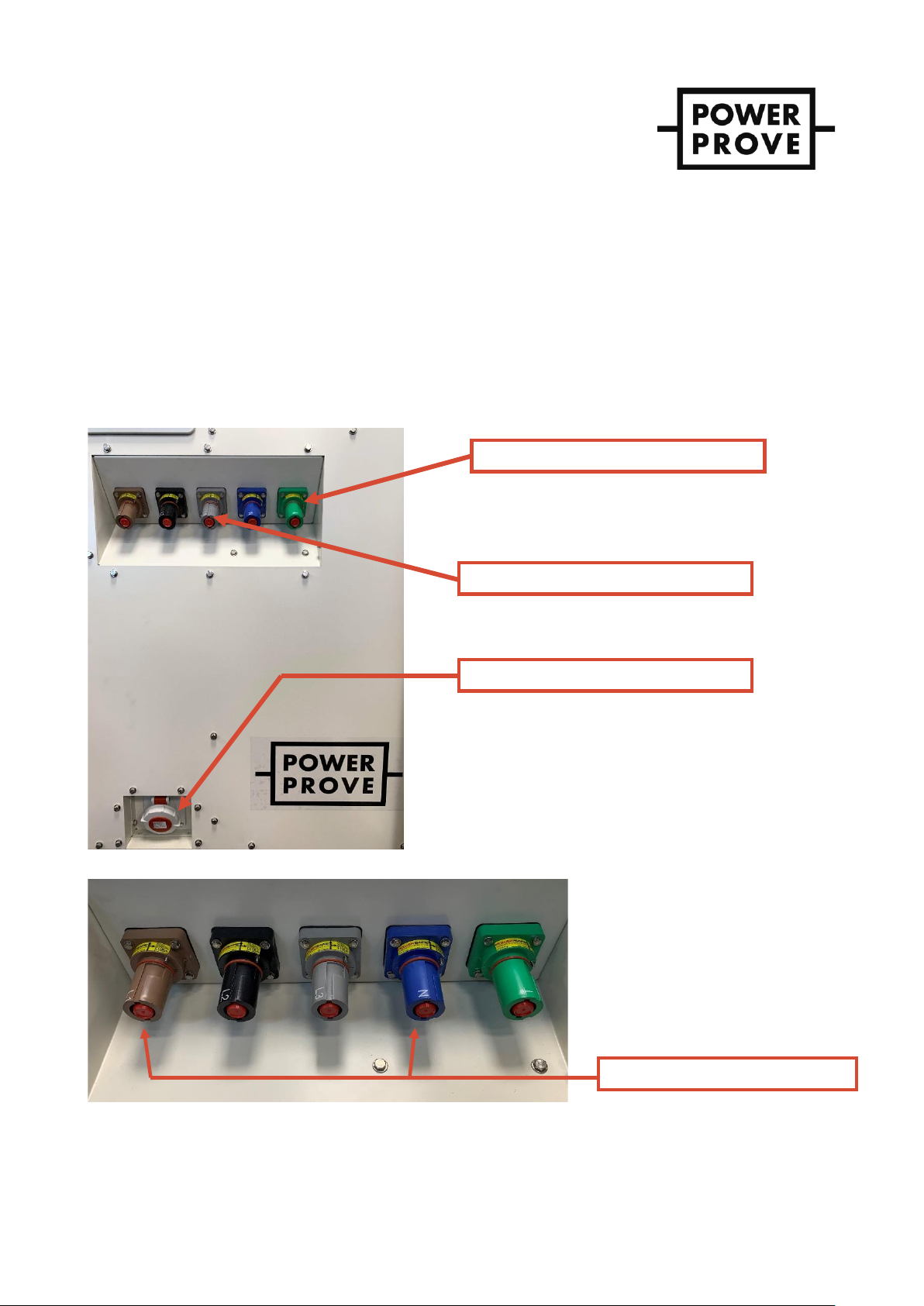
Power Connections ....................................................................................................................................................................................4
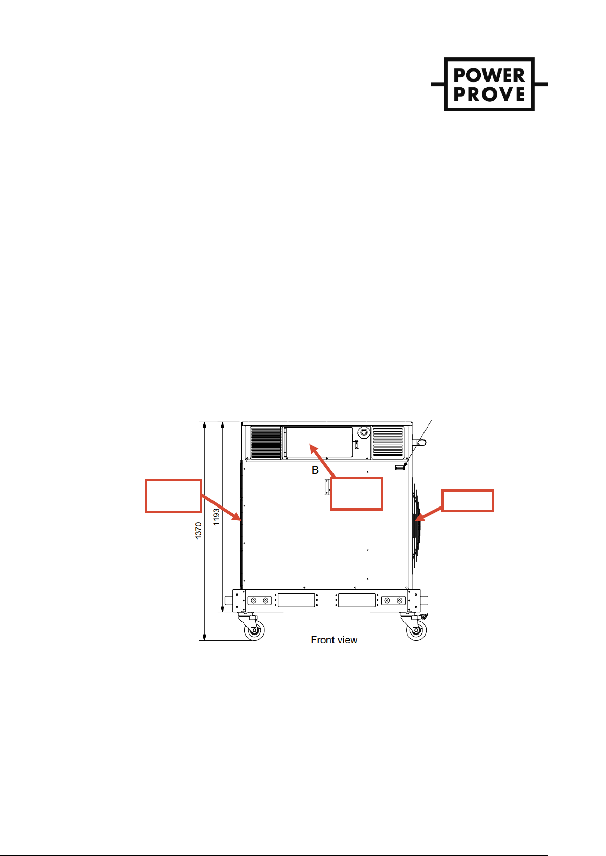
Ventilation ................................................................................................................................................................................................... 4
4) Operating Instructions ..........................................................................................................................................................................6
Connections ................................................................................................................................................................................................. 6
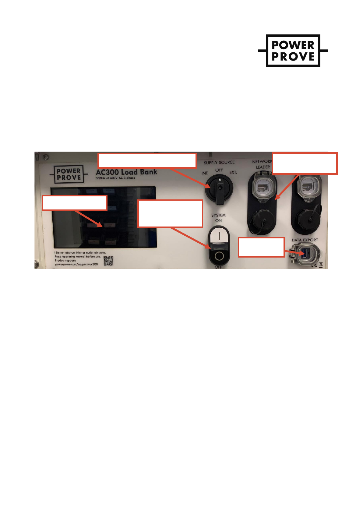
Controls........................................................................................................................................................................................................ 7
Pre-start-up.................................................................................................................................................................................................7
Start-up........................................................................................................................................................................................................ 7
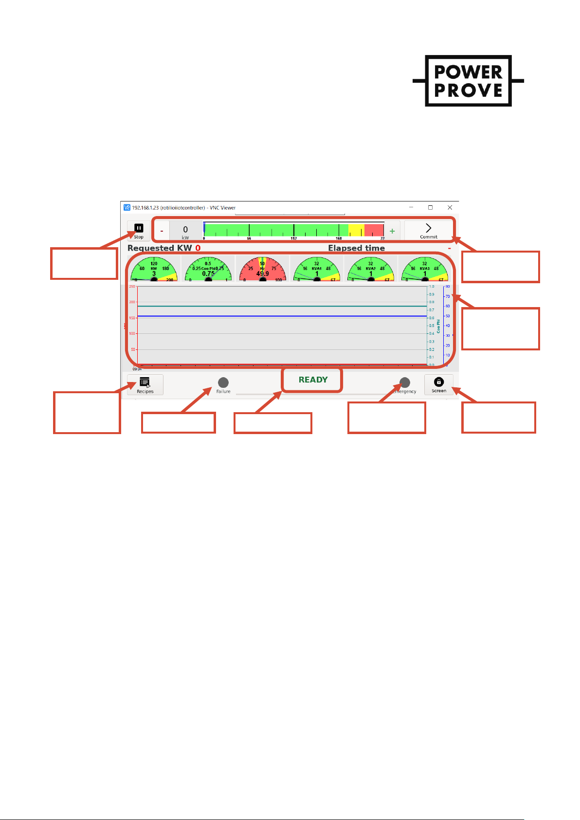
DIGILOAD HMI........................................................................................................................................................................................... 8
Applying & disconnecting load .............................................................................................................................................................. 8
Switching off and disconnection .............................................................................................................................................................9
Load cycles ‘recipes’.................................................................................................................................................................................9
HMI Menus...................................................................................................................................................................................................9
Alerts menu............................................................................................................................................................................................. 9
Operating mode menu ......................................................................................................................................................................10
Power measurements menu...............................................................................................................................................................10
Lock screen................................................................................................................................................................................................11
Exporting test data over USB...............................................................................................................................................................11
5) Maintenance.........................................................................................................................................................................................12
6) Spares ...................................................................................................................................................................................................12
7) Waste Electrical & Electronic (WEEE) Disposal Instructions........................................................................................................12

Document Operating and Maintenance manual, AC200
Reference No. 164571
Revision A
Date 23-JUL-2021
Author AK
Power Prove www.powerprove.com
Leicester. LE5 5LZ. United Kingdom sales@powerprove.com
a division of Cressall Resistors Ltd. +44(0) 116 249 1722 Page 2 of 12
Operating and maintenance manual
200kW load bank rated at 400V AC 3-phase with 5kW steps
Figure 1 - Product photo.
1) Warnings
Prior to use
Operators of this equipment should be of suitable competency to perform electrical testing and must have read and
understood this document.
First use
ELE CT RIC SH OCK HA ZARD ! Electric shock can lead to severe injury or death. If the load bank has been
damaged in transit, do not operate until a competent technician inspects the unit and
determines that it can be operated safely.
Check the equipment for obvious damage. Document and report any exterior damage immediately.
During use
Review the safety requirements stated this document (Section 3) before using the equipment.
FI RE AN D B URN S H A ZA RD ! When using the load bank, the exit grill and adjacent covers will become
hazardously hot to touch and remain hot for approximately after testing is
completed, whilst the load bank performs its cooling down period. The exiting air
will also be hot ~100°C above ambient at 1m from the exit grill.

Document Operating and Maintenance manual, AC200
Reference No. 164571
Revision A
Date 23-JUL-2021
Author AK
Power Prove www.powerprove.com
Leicester. LE5 5LZ. United Kingdom sales@powerprove.com
a division of Cressall Resistors Ltd. +44(0) 116 249 1722 Page 3 of 12
2) Product specification
Ratings
Operating environment
Voltage, V
400, 3-phase
Service condition
Outdoor use
Frequency, Hz
50
Ambient temperature
-10°C to 50°C
Load steps, kW
5, 10, 15, 20, 50, 100
Humidity
95% RH
Total capacity, kW
200
Ingress protection
IP23 Load enclosure
IP54 Control
compartment
Control and ventilation
Construction
Manual controls
System on/off pushbuttons,
supply rotary selector
switch, emergency stop
Resistor elements
Stamped grid and wire
coils
Control interface
7” touch screen display
Element material
Stainless steel
Cooling
Forced convection,
horizontal orientation
Enclosure
Dual layer; galvanized
sheet steel, painted
RAL9002 grey
Fan(s)
1 x 2.7kW fan, axial type
Manoeuvrability
4 x heavy duty castors,
forklift pockets.
Control supply
400V 3-phase, 3-wire AC
Source
Internal (supply under test)
or external supply
(recommended)
Weight and dimensions
Drawing reference
164043
Connection interfaces
Length, mm
1175
Load connections
5 x Powersafe sockets
(3P+ N + PE)
Width, mm
806
Control supply
1 x EN 60309 3P+PE 16A
Height, mm
1370
Data downloads
USB Type-A
Weight, kg
240
Networking/remote
2 x RJ45
Safety
Electrical protection
Over current and short
circuit fuse protection
Over voltage protection
(via control system)
Thermal protection
PT100 monitoring (load
and control compartments)
PT100 healthy status
Airflow status

Document Operating and Maintenance manual, AC200
Reference No. 164571
Revision A
Date 23-JUL-2021
Author AK
Power Prove www.powerprove.com
Leicester. LE5 5LZ. United Kingdom sales@powerprove.com
a division of Cressall Resistors Ltd. +44(0) 116 249 1722 Page 4 of 12
3) Safety
General
When using this equipment basic precautions should always be followed to reduce the risk of fire, electrical shock, and
injury to persons, including the following:
1) Do not operate the load bank with a damaged cables or plugs or after the malfunction of the equipment
itself or if it has been dropped or damaged in any manner. Discard the load bank or return to authorized
service facility for examination and/or repair.
2) Always unplug the load bank when not in use.
3) Do not use the load bank in areas where flammable liquids are used or stored.
4) Before use perform a visual inspection of the resistor duct by shining a torch into each end of the duct (fan
side and resistor bank side) and ensure there has been no ingress of materials, vermin etc. that could
impede the airflow or cold ignite once the resistor elements are hot.
5) Perform a walk around of the equipment and ensure all fixings are tight. If there are any obvious signs of
damage, please contact Power Prove for support before connecting a power source.
Protective earth bonding
ELE CT RIC SH OCK HA ZARD ! The protective earth socket must be connected to an external earth point. Operating
without a grounding connection could lead to injury or death.
When the load bank is in operation, the protective earth socket must be securely, electrically connected to an external
earth point. The bonding connection provides a low resistance path to earth. This protects the operator from the
possibility of electrical shock.
Power Connections
ELE CT RIC SH OCK HA ZARD ! All power connections must be connected or guarded. Failure to do so will expose
operators to electric shock, leading to severe injury or death.
B UR NS & S H OC K H A ZA RD ! Connecting or disconnecting plugs and receptacles while current is flowing, or
voltage is present may cause arcing. Arcing can generate a great deal of light,
heat, and possibility of electrocution.
FIRE HAZA RD ! Do not run cables under carpeting. Do not cover cord with throw rugs, runners, or
similar coverings.
TR IP H A ZA RD ! Arrange cables away from high foot traffic areas, where they will not present a trip
hazard.
Ventilation
Aside from the connections the most critical aspect of safe load bank operation is the ventilation. Load banks become
very hot during operation and failure to provide sufficient ventilation and adherence to the following instructions could
cause fire, burns and/or other injuries.
In principle, high volumes of cooling air are needed to prevent load elements from overheating. By their very nature,
resistors under load convert electrical energy to heat. This heat must be removed from the unit. The air inlet and outlets
are sized to provide the proper amount of cooling air. Preventing or limiting airflow will cause the load bank to
overheat.

Document Operating and Maintenance manual, AC200
Reference No. 164571
Revision A
Date 23-JUL-2021
Author AK
Power Prove www.powerprove.com
Leicester. LE5 5LZ. United Kingdom sales@powerprove.com
a division of Cressall Resistors Ltd. +44(0) 116 249 1722 Page 5 of 12
Typical temperatures of the load bank:
•Resistor elements ~500degC above ambient (light/red glow)
•Air outlet surfaces ~250degC above ambient
•Exhaust air ~100degC above ambient at 1m from the outlet
FI RE A ND B URNS H AZA RD ! Failure to maintain proper housekeeping and properly securing flammable material
could lead to fire, burns, and/or injury. Instructions for safe ventilation of the load
bank:
1) Position the load bank on a flat surface that is free from surface finishes or contamination that are flammable.
2) Provide 2m clearance around the load bank inlet and sides, and 4m from the air outlet.
3) Never block or obstruct the air inlets or outlets in any way.
4) Clear any combustible material out of the test vicinity including light materials that could be drawn into the inlet
by the force of the fan suction.
5) Material can be moved by the force of the fan airflow and both the air intake and exhaust. Failure to secure
material could cause injury to bystanders, damage to the load bank or other nearby equipment.
6) Do not let bare skin touch hot surfaces to avoid burns.
7) Do not insert or allow foreign objects to enter any ventilation or exhaust opening as this may cause an electric
shock, fire, or damage the heater/load bank.
8) Always permit the load bank to run its cooling cycle at the end of a load run, this allows the resistor elements
and supporting insulation materials to cool properly. Failure to do so may shorten the resistor element service
life.
9) Ductwork must not be attached to either the air intake or exhaust of this load bank. This will cause a
backpressure that may be harmful to the resistors.
Figure 2 - Unit front view showing ventilation areas
Air inlet
Hot air
outlet
Control
panel

Document Operating and Maintenance manual, AC200
Reference No. 164571
Revision A
Date 23-JUL-2021
Author AK
Power Prove www.powerprove.com
Leicester. LE5 5LZ. United Kingdom sales@powerprove.com
a division of Cressall Resistors Ltd. +44(0) 116 249 1722 Page 6 of 12
4) Operating Instructions
IMPO RTANT ! Read section 3, safety instructions before continuing.
Connections
Ensure the protective earth connection is made first, then connect the external control supply if (as recommended) you are
using this, and finally the load power connections (See Figure 3). Otherwise ensure the unit’s Control Source switch is
properly set and the voltage input to the Powersafe sockets is appropriate to supply the units control circuits as well as
the full load.
Connection sockets to be used for 1-phase operation are shown in Figure 4Error! Reference source not found..
Figure 3 - Powersafe load connections, control power (C14 socket) and Protective Earth stud
Figure 4 - Load power connections showing 1-phase configuration.
Protective earth connection
Load connections; L1, L2, L3 and N.
External supply socket (16A, 3P + PE)
1-phase testing use sockets L1 and N.

Document Operating and Maintenance manual, AC200
Reference No. 164571
Revision A
Date 23-JUL-2021
Author AK
Power Prove www.powerprove.com
Leicester. LE5 5LZ. United Kingdom sales@powerprove.com
a division of Cressall Resistors Ltd. +44(0) 116 249 1722 Page 7 of 12
Controls
The load bank is controlled from the panel fitted to the load bank behind the padlock-able access door –see Figure 5.
IMPO RTANT ! The unit is also fitted with an emergency stop button, located outside of the area covered by
the control access door to always be accessible. The emergency stop cuts power to the load
contactors and the load cooling fans. Using the emergency stop will mean the latent heat of
each resistor element is retained and the load bank will take a significant period to cool
down. Therefore, use of the emergency stop should be reserved for its intended purpose and
the controlled shut-down process described later should be used for all other occasions.
Figure 5 –User control panel.
Pre-start-up
1. Check housekeeping in the area in which the load bank is operating and rectify anything that is unsafe or
does not comply with the safety instructions in section 3. Failure to do this presents a significant fire hazard.
2. Connect the load bank’s protective earth connection to a known external earth point.
3. Ensure all power supply and load connections are well made, no conductors are exposed, cable sizes used
are appropriate and suitably positioned for the conditions.
Start-up
1. The control circuitry including the load and cabinet cooling fans can either be supplied directly
from the main load connections or from a separate supply using the provided 16A 3-phase socket.
The latter is preferred because should the supply under test cut off the cooling fans will be
supplied ensuring the load bank is not left without cooling. Select the supply source using the
selector switch.
i. “INT.” or internal uses the main supply connected to the load Powersafe sockets.
ii. “EXT.” or external uses supply from the 16A commando socket.
The white LED in the system on/off cluster should now be illuminated indicating the control
circuitry has power.
The cabinet conditioning circuit (ventilation fans and anti-condensation heater) now has power
and will begin to operate.
Touchscreen display
Supply source rotary selector switch
System on/off buttons
and supply healthy
indicator LED
Remote and network
connection points
USB port for
data export

Document Operating and Maintenance manual, AC200
Reference No. 164571
Revision A
Date 23-JUL-2021
Author AK
Power Prove www.powerprove.com
Leicester. LE5 5LZ. United Kingdom sales@powerprove.com
a division of Cressall Resistors Ltd. +44(0) 116 249 1722 Page 8 of 12
2. Switch on the system using the white ON button marked “I”. The internal control system computer
will now begin its start-up boot sequence, this will take around 2 minutes. When the boot sequence
is complete you will see the Human Machine Interface (HMI) displayed on the touchscreen monitor.
3. The system status will be displayed as “IDLE” –see Figure 6.
DIGILOAD HMI
Figure 6 - DIGILOAD HMI interface
Applying & disconnecting load
1. Before any load can be applied the fan must be running. With the control system status displayed as IDLE,
start the fan using the Start/Stop button in the top left corner for the HMI.
2. When the fan has started the system status will change from “IDLE” to “READY”. Check that the airflow is in
the right direction, into the fan and out of the resistor bank grill.
3. To apply load press and hold the “+” or “-“ buttons until the desired load is shown in the load selection
window and then press “Commit” to confirm the selection. The appropriate contactors will immediately
operate, and the load is applied.
4. The power measurement window will display the measured values confirming the load applied to the
device under test.
5. Further adjustments to the load can be made by repeating the process described in point 3.
6. When the testing is complete simply press the “Start/Stop” button which will change state to show
“Confirm”. Press again to confirm and the load bank status will change to “COOLING DOWN”. This
sequence ramps down the load and then continues to run the fan for the required cooling time. The cool
down progress bar is displayed below the system status.
7. Once complete the system status will return to IDLE and the load bank can be switched off by pressing and
holding the black off button marked “O” for 5 seconds. The internal PSU contactor will de-energise and the
HMI screen will switch off.
Start / Stop
button
Pre-set load
‘recipes’
menu button
Alert indicator
Load selection
interface
Power
measurement
display window
Screen lock
function
Emergency stop
status indicator
System status

Document Operating and Maintenance manual, AC200
Reference No. 164571
Revision A
Date 23-JUL-2021
Author AK
Power Prove www.powerprove.com
Leicester. LE5 5LZ. United Kingdom sales@powerprove.com
a division of Cressall Resistors Ltd. +44(0) 116 249 1722 Page 9 of 12
Switching off and disconnection
1. Once the HMI display is off, the control system powered down. The internal control supply still has power -
as indicated by the white LED. This can be switched off using the rotary selector switch.
2. The power connections can now be disconnected in reverse order (protective earth last) and the unit is
ready for storage. Note –there may still be some remnant heat in the load bank and so caution is still
advised in terms of proximity to flammable materials and still permit free movement of air for at least 1
hour after use.
Load cycles ‘recipes’
The load bank can run a series of different load levels that can be pre-programmed and recalled at any time. In
addition, the load bank records each load test completed and can be recalled from the same menu.
Figure 7 - Recipe menu
HMI Menus
The DIGILOAD HMI has some slide out menus to give access to additional parts of the system. These are accessed from
the arrow icons along the bottom edge of the screen. There are 3 arrows positioned in the bottom left, bottom centre
and bottom right respectively.
Alerts menu
The central arrow brings up the system status menu which included the status of the feedback from each load contactor,
the PT100 temperatures measurements and alerts when they occur.
For each contactor the letters “O” or “C” are displayed for open or closed respectively.
When an alert occurs the load bank will immediately perform a controlled shutdown. This is where the load steps a switch
off one at a time and the cool down timer is run on the fan.
When an alert is cleared i.e., a temperature falls back into range, press the “Alerts rest” button to clear it and enable
the load bank to be run again.
Recipe name
Recipe load
steps and
durations
Run the
selected
recipe
Cancel the
recipe selection
Save the recipe
selection
Recipe step
configuration

Document Operating and Maintenance manual, AC200
Reference No. 164571
Revision A
Date 23-JUL-2021
Author AK
Power Prove www.powerprove.com
Leicester. LE5 5LZ. United Kingdom sales@powerprove.com
a division of Cressall Resistors Ltd. +44(0) 116 249 1722 Page 10 of 12
Figure 8 - Alerts menu
Operating mode menu
The bottom right arrow brings up the operating mode menu. This permits the user to select the voltage being applied (if
different to the nominal design value of the load bank) so that the system can scale the load steps accordingly. It also
allows the user to limit the power of the load bank when being used to test a supply with a lower power rating than that
of the load bank itself. This is done by adjusting the load bank power using the plus and minus buttons.
Figure 9 - Operating mode menu
Power measurements menu
Use the arrow icon in the bottom left corner of the HMI to display the power measurements menu. Here all the measured
voltages, currents and power values are displayed as numeric values. The user can select which set of values to display
on the main screen from the buttons labelled with the corresponding units of measure.
As with all the menus the parameter display menu can be opened at any time whether load is being applied or not. This
screen can be particularly useful if the user wishes to read a precise value.

Document Operating and Maintenance manual, AC200
Reference No. 164571
Revision A
Date 23-JUL-2021
Author AK
Power Prove www.powerprove.com
Leicester. LE5 5LZ. United Kingdom sales@powerprove.com
a division of Cressall Resistors Ltd. +44(0) 116 249 1722 Page 11 of 12
Figure 10 –Power measurements menu
Lock screen
To prevent accidental button presses during testing the HMI can be locked using the icon on the home screen. To unlock
the screen simply press each of the 4 buttons.
Figure 11 - Lock screen
Exporting test data over USB
The load bank is equipment with a panel mounted USB port and the DIGILOAD system prepares all recorded power
data for export after each test completed.
To download the test data simply insert a FAT32 formatted USB drive into the port. The data download will immediately
begin, and the HMI will display a message to that effect. Do not remove the USB drive until instructed to do so.
It may take a few minutes for the data export process to complete; depending on the amount of data stored and the
speed of the USB drive used.

Document Operating and Maintenance manual, AC200
Reference No. 164571
Revision A
Date 23-JUL-2021
Author AK
Power Prove www.powerprove.com
Leicester. LE5 5LZ. United Kingdom sales@powerprove.com
a division of Cressall Resistors Ltd. +44(0) 116 249 1722 Page 12 of 12
The data exported will be in a .CSV file which can be opened with all common spreadsheet software. The recorded
data is formatted into columns by parameter.
5) Maintenance
The load bank is designed to require minimal maintenance, a list of required maintenance checks is listed below in table
4.
The separate (external) 3-phase supply can be used to check the fan is operating correctly and to perform an insulation
resistance and load resistance test every 6 months. With control circuit powered from the external supply, run the fan,
and use the HMI to close all contactors (see load to 200kW and all contactors will close). Connect a suitable test device
(insulation tester and digital ohmmeter) to lug connections of the protective earth and power connection cables to make
the contact with the internal connectors. When checking the resistance ensure the resistance of the cables being used is
taken into consideration.
Action
Frequency
Walk around the unit and inspect for:
a) Obvious damage
b) Loose hardware
Every use
Inspect resistor duct –visual inspection
Every use
Insulation Resistance Test
Every 6 months
Cold Resistance Check (0.8Ω Line to Neutral per phase)
Every 6 months
Table 1 - Routine maintenance checks table
Further maintenance should be completed by the manufacturer. Please contact us to arrange for the load bank to be
booked in for inspection, repair, and re-test.
6) Spares
Enquire with reference to resistor product code and serial number, as shown on rating plate.
We offer a full equipment inspection, repair (when necessary) and re-test service for any of our load banks at our
headquarters in Leicester, UK.
7) Waste Electrical & Electronic (WEEE) Disposal Instructions
European directive 2012/19/EU Waste Electrical and Electronic Equipment (WEEE) GB this appliance is marked
according to the European directive 2012/19/EU on Waste Electrical and Electronic Equipment (WEEE). By ensuring that
this product is disposed of correctly. You will help prevent potential negative consequences for the environment and
human health, which could otherwise be caused by inappropriate disposal of this product.
The symbol on the product, or on the documents accompanying the product, indicates that this appliance must
not be treated as municipal waste. Instead, it must be handed over to a licensed waste carrier and waste broker
approved by the Environment agency under the Waste (England and Wales) Regulations 2011.
This manual suits for next models
1
Table of contents
Popular Accessories manuals by other brands

Verilux
Verilux CleanWave VH01WW4 manual

Listen Technologies
Listen Technologies LBB 1900 Specification sheet

PCB Piezotronics
PCB Piezotronics 357E93 Installation and operating manual

HEIDENHAIN
HEIDENHAIN ERN 430 Mounting instructions

Environmental Instruments
Environmental Instruments AQMesh operating manual

Silvercrest
Silvercrest SPBD 5000 A1 operating instructions