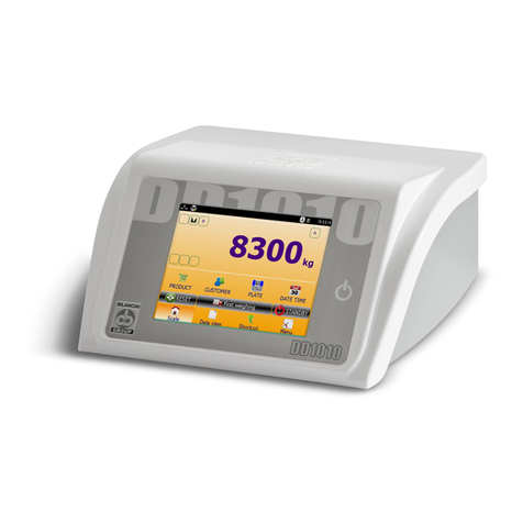
Bilanciai DD1050 User manual


3
DD1050
TABLE OF CONTENTS
1 INTRODUCTION ................................................................................ 7
1.1 Foreword ................................................................................................7
1.2 Documentation ........................................................................................8
1.3 Symbols .................................................................................................8
1.4 Description of the terminal ......................................................................9
1.5 Technical characteristics of the terminal .................................................. 10
1.6 Declaration of conformity ...................................................................... 11
1.7 Overall dimensions and weight of terminal............................................... 12
1.7.1 Table version ........................................................................................ 12
1.7.2 Wall version.......................................................................................... 12
1.8
How to dispose of electric or electronic waste............................................ 13
1.9 How to obtain technical assistance.......................................................... 13
1.10 Warranty............................................................................................. 13
1.11 SPARE PARTS ...................................................................................... 14
2 SAFETY INSTRUCTIONS ................................................................. 18
2.1 Forbidden uses .................................................................................... 18
2.2 Regulations ......................................................................................... 18
2.3 Instructions for use .............................................................................. 18
3 DELIVERY AND INSTALLATION ....................................................... 19
3.1
Installation........................................................................................... 20
3.1.1 Table installation ................................................................................... 20
3.2
Connection of the terminal to the electricity main ...................................... 20
3.2.1 Inspections........................................................................................... 20
3.2.2 Wiring diagram ..................................................................................... 21
3.2.3 Power cable ........................................................................................... 21
3.3 12 V dc power supply ............................................................................. 22
3.4 CONNECTION OF THE TERMINAL TO THE WEIGHING PLATFORM ................. 22
3.4.1 Wiring diagram ..................................................................................... 23
3.4.2 Equipotentiality between terminal and weighing platform ............................ 23
3.4.3 Digital Scale serial connection ................................................................. 24
3.4.4 Analog Scale serial connection................................................................. 24
3.5 SERIAL LINKS ....................................................................................... 25
3.5.1 COM2 serial link .................................................................................... 25
3.5.2 COM3 serial link .................................................................................... 25
3.5.3 RS232 connections ................................................................................ 26
3.5.4 RS422 connections ................................................................................ 26

4
DD1050
3.5.5 RS485 connections ................................................................................ 26
3.6 INPUTS / OUTPUTS............................................................................... 27
3.6.1 Input connection .................................................................................... 28
3.6.2 Output connection ................................................................................. 28
4 CONTROLS, SWITCHING ON AND OFF ............................................. 29
4.1 On-off key ............................................................................................ 29
4.2 Touch screen......................................................................................... 30
4.3 External keyboard and mouse ................................................................ 30
5 USE OF THE TERMINAL ................................................................... 31
5.1 Main window for the double weighing mode ............................................. 31
5.1.1 General information ............................................................................... 31
5.1.2 Metrological keys................................................................................... 31
5.1.3 Weight indication (on the left-hand side of the weight value) ....................... 32
5.1.4 Weight indication (on the right-hand side of the weight value) ..................... 32
5.1.5 Weight indications ................................................................................. 33
5.1.6 Current data table ................................................................................. 33
5.1.7 Operation ............................................................................................. 33
5.1.8 Status bar ............................................................................................ 34
5.1.9 Menu ................................................................................................... 34
5.1.10
Reprint................................................................................................. 34
5.1.11
Logo .................................................................................................... 34
5.2 Scale Test window ............................................................................... 34
5.3 Parameter customising window .............................................................. 35
5.3.1 General information ............................................................................... 35
5.3.2 Keys .................................................................................................... 35
5.3.3 Exit key................................................................................................ 35
5.4 Archive customising window .................................................................. 36
5.4.1 General information ............................................................................... 36
5.4.2 Keys .................................................................................................... 36
5.5 Totals management window................................................................... 37
5.5.1 General information ............................................................................... 37
5.5.2 Keys .................................................................................................... 37
5.6 Weighing parameter customising window (SETUP) .................................... 37
5.6.1 General information ............................................................................... 37
5.7 Metrological info display window............................................................. 38
5.7.1 General information ............................................................................... 38
6 OPTIONAL EQUIPMENT ................................................................... 39

5
DD1050
7 ERROR MESSAGES........................................................................... 40
7.1 Terminal errors .................................................................................... 40
7.2 Scale errors......................................................................................... 40
7.3 Area codes and errors........................................................................... 42
7.4 List of categories and details.................................................................. 51
7.4.1 PluginCbConguration ............................................................................ 51
7.4.2 PluginCbControlsFull .............................................................................. 51
7.4.3 PluginCbDeviceAccess ............................................................................ 52
7.4.4 PluginCbDeviceAccessScale..................................................................... 52
7.4.5 PluginCbDoubleWeight ........................................................................... 54
7.4.6 PluginCbMainWeight............................................................................... 55
7.4.7 PluginCbWeightViewer............................................................................ 56
8 PROGRAMMING DIALOGUES VIA SERIAL LINKS ............................. 57
9 PARAMETER CUSTOMISING ............................................................ 58
9.1 Core.Password.Config.ConfigSchema.xml ................................................ 58
9.2 Core.PLC.Config.ConfigSchema.xml ........................................................ 58
9.3 D404681.xml....................................................................................... 58
9.4 D404701.xml....................................................................................... 64
9.5 SUM_SCALE.xml .................................................................................. 70
9.6 Bilancia.BilanciaRemota.ConfigSchema.xml.............................................. 76
9.7 CbDoubleWeight.Config.ConfigSchema.xml.............................................. 77
9.8 CbDoubleWeight.ConfigRcA.ConfigSchema.xml......................................... 77
9.9 CbDoubleWeight.ConfigRcD.ConfigSchema.xml ........................................ 79
9.10 CbDoubleWeight.ConfigRcP.ConfigSchema.xml......................................... 81
9.11 CbMainWeight.Config.ConfigSchema.xml ................................................. 83
9.12 CbMainWeight.ConfigFields.ConfigSchema.xml ......................................... 86
9.13 CbMainWeight.ConfigInputDosageStart.ConfigSchema.xml......................... 87
9.14 CbMainWeight.ConfigInputDosageStop.ConfigSchema.xml ......................... 87
9.15 CbMainWeight.ConfigInputOperationEnable.ConfigSchema.xml................... 87
9.16 CbMainWeight.ConfigInputScaleReset.ConfigSchema.xml........................... 88
9.17 CbMainWeight.ConfigInputScaleSelect.ConfigSchema.xml.......................... 88
9.18 CbMainWeight.ConfigInputSetPointDisable.ConfigSchema.xml .................... 89
9.19 CbMainWeight.ConfigInputTareReset.ConfigSchema.xml............................ 89
9.20 CbMainWeight.ConfigInputTareSet.ConfigSchema.xml............................... 90
9.21 CbMainWeight.ConfigInputTareSetReset.ConfigSchema.xml ....................... 90
9.22 CbMainWeight.ConfigInputTransmissionOperation.ConfigSchema.xml.......... 91
9.23 CbMainWeight.ConfigInputWeighingOperation.ConfigSchema.xml ............... 91
9.24 CbMainWeight.ConfigInternal.ConfigSchema.xml ...................................... 91

6
DD1050
9.25 CbMainWeight.ConfigOutputEndPrint.ConfigSchema.xml ............................ 92
9.26 CbMainWeight.ConfigOutputEndTransmission.ConfigSchema.xml ................ 92
9.27 CbMainWeight.ConfigOutputRange.ConfigSchema.xml............................... 92
9.28 CbMainWeight.ConfigOutputSelectedScale.ConfigSchema.xml .................... 93
9.29 CbMainWeight.ConfigOutputSetPoint.ConfigSchema.xml ............................ 93
9.30 CbMainWeight.ConfigOutputSlow.ConfigSchema.xml ................................. 94
9.31 CbMainWeight.ConfigOutputTrafficLight.ConfigSchema.xml ........................ 94
9.32 CbMainWeight.ConfigPrint.ConfigSchema.xml........................................... 95
10
CUSTOMISING METROLOGICAL PARAMETERS......................................97
10.1 Internal scale calibration ....................................................................... 98
11 HOW TO DISASSEMBLE THE COMPONENTS ..................................... 99
11.1 Opening the terminal ............................................................................ 99
11.2 Disassembly of the backlighting lamp inverter ........................................ 101
11.3 Disassembly of the front panel and display ............................................ 102
11.4 Disassembly of the digital/analog scale power supplier ............................ 103
11.5 Disassembly of the lithium battery........................................................ 104
11.6 Disassembly of the mother board ......................................................... 105
11.7 Disassembly of the core board ............................................................. 106
11.8 Disassembly of the RS232/422/485 serial output boards ......................... 107
11.9 Scale input disassembly ...................................................................... 108
11.9.1
Analog scale input board .......................................................................108
11.9.2
Digital scale input module......................................................................109
11.10
Disassembly of the electrical connections ............................................. 110
11.11
Optional board installation.................................................................. 111
11.12
Connection of serial port and flash drive peripherals............................... 111

7
DD1050
1 INTRODUCTION
1.1 Foreword
• The aim of this manual is to provide the operator, through the use of text and illustrations,
with essential information regarding the installation, correct operation in safe conditions, and
methodic maintenance of the weighing system.
• Always keep this manual at hand! Always observe the instructions contained in the manual!
• Safe operation of the system is the responsibility of the operator, who must be fully familiar
with it.
• The user is responsible for ensuring that the installation conforms to the applicable
regulations.
• The equipment must only be installed by specialised personnel who have read and understood
this manual.
• “Specialised personnel” means any personnel who, by virture of the training they have
received and their professional experience, have been explicitly authorised by the “System
safety supervisor” to install, operate and service the system.
• Contact your nearest Service Centre if problems occur.
• Any attempt on the part of the user or unauthorised personnel to dismantle, modify or
tamper with the terminal is prohibited. Any such attempt shall invalidate the warranty and
relieve the manufacturer from all liability for any damage or injury to persons or property.
• It is also forbidden to alter or remove the data plates and seals on the terminal. Make sure
that all plates and seals are present and legible, if not contact the After-Sales Service.
• The Manufacturer shall not be liable for any damages caused by incorrect handling of the
terminal.
• The information and illustrations contained in this manual were up to date at the time of
publication.
• The manufacturer is committed to a policy of continuous product improvement and parts of
thesystemmaythereforebesubjecttomodication.
• All the technical information contained in this manual remains the exclusive property of the
Manufacturer and may not be disclosed to third parties.
• No part of this document may be reproduced or transmitted in any form, including publication
in computerised form or on the World Wide WEB, without the explicit written permission of
the manufacturer.
• This manual may not be used for purposes other than those directly related to installation,
operation and maintenance of the terminal.
• In order to more clearly describe certain maintenance or adjustment operations, some of
the illustrations in this manual show the weighing system with the safety guards removed.
Under no circumstances may the system be operated in these conditions. The safety guards
may only be removed for the time strictly required to carry out the required repairs or
maintenanceworkafterwhichtheymustbettedbackinplace.

8
DD1050
1.2 Documentation
The standard documentation supplied with terminal DD1050 includes:
• QUICK START
Multi-language, printed on paper, brief instructions for immediate use, declaration of
conformity and principal danger warnings.
• OPERATION, MAINTENANCE AND INSTALLATION MANUAL
The multi-language one you are reading, stored on a CD with les in the PDF and HTML
format. A version printed on paper can be supplied on request.
• COMMUNICATION MANUAL
multi-language,storedonaCDwithlesinthePDFformat.Aversionprintedonpapercan
be supplied on request.
The following software programming manuals are only supplied on request:
• HOW TO DIADE (pdf)
• HOW TO GRAPHIC USER INTERFACE (GUI) DESIGN (pdf)
• PLC CUSTOMIZATION DIADE (pdf)
• PLC MANUAL (HTML Zip)
Contact our Sales and Assistance network's After-Sales service
1.3 Symbols
Below is a list of the symbols used in this manual to alert the reader to the various hazards
associated with the operation and maintenance of the terminal.
DANGER
Denotes an operation or procedure where failure to observe the instructions will result in death
or serious injury.
CAUTION
Information or procedure where failure to observe the instructions could result in minor injury
or damage to the instrument.
WARNING
Information or instructions on how the system is to be operated correctly in order to maximize its
service life or prevent loss or damage of programmed data or to optimize operation with regard
to metrological standards.

9
DD1050
1.4 Description of the terminal
Terminal DD1050 allows highly accurate and reliable weighing operations to be carried out.
• It is designed for industrial use.
• Metrological software for weight management is part of the standard equipment supplied.
• ABS case and steel front, available in both table and wall-mounted versions.
• Simple and immediate use with the 10.4” “Touch screen” colour display.
• Flexible, with customizable functions and graphic appearance.
• Equipped with a powerful SQL relational data-base for managing the weighing data.
• Advanced network connectivity and communication.
• Programming and customising by means of PC via the network.

10
DD1050
1.5 Technical characteristics of the terminal
Power supply
Direct 12 Vdc/5 A (Min 11 V - Max 15 V)
Via network adapter L+N+R
110 - 240 Vac (-15% … +10%)
1.8 A
50 - 60 Hz
60 W Max
Ground connection Equipotential type for weighbridges
Scales
Total 1/2
(or 1 analog, or 1 digital, or 2 analogs or 2 digitals)
Slave operating mode
Analog scale
Load cells that can be connected Up to twelve 350 Ohm analog cells per scale
Minimum impedance 29 Ohm per scale
Load cell power supply 10 Vdc
Internal resolution 200000 points @ 25 conv/s
Resolution in type-approved version Up to 6000 divisions or two 3000 ranges
Maximum input signal 35 mV
Sensitivity 0.6 µV/division
Full scale stability < 5 ppm/°C
Zero stability < 5 ppm/°C
Digital scale
Load cells that can be connected Up to one scale with 12 digital load cells or two
scales with 8 digital load cells
Minimum impedance 80 Ohm
Load cell power supply 10 to 15 Vdc
Internal resolution 200000 points @ 25 conv/s
Resolution in type-approved version Up to 6000 divisions or two 3000 ranges
Environmental specications
Compensated temperature range From -10 to + 40 °C
Operating range From -10 to + 40 °C
Maximum humidity 85% @ 40 °C
IP protection degree IP 20, Front IP 65
User interface
Video 10.4” backlighted TFT display
Keyboard Touch screen

11
DD1050
Communication ports
USB Type B 1
USB Type A 2 (+1 internal)
Serial ports 1 RS232/422/485 – 1 RS232
Ethernet 10/100 1
Inputs 2
Output 2
Data stores
SD Card 1
Compact Flash 1
Expansions
Optional board slots 3
1.6 Declaration of conformity
See QUICK START manual.

12
DD1050
1.7 Overall dimensions and weight of terminal
1.7.1 Table version
I--(Figure1-1a.jpg)--I
Figure 1.1 - Dimensions of the weighing terminal
• Dimensions(giveninmm):seegure1.1.
• Weight: 5 kg
1.7.2 Wall version
I--(Figure1-1b.jpg)--I
Figure 1.2 - Dimensions of the weighing terminal
• Dimensions(giveninmm):seegure1.2.
• Weight: 5 kg

13
DD1050
1.8
How to dispose of electric or electronic waste
This symbol on the weighing device purchased means that:
• This electrical or electronic device cannot be disposed of as solid urban
waste.
• It must be disposed of separately.
• It can be returned to the dealer when a new one is purchased.
• Improper use or disposal of this device could pollute the environment
or damage human health.
• Failure to comply with the aforementioned indications is punishable by
law.
In particular:
• The outer casing and the mechanical components are made of plastic and/or metal
materials.
• The casing houses printed circuits with electronic components.
• The electrical connections are made with insulated copper conductors.
CAUTION
This equipment must be disposed of separately or taken to the dealer or a differentiated waste
disposal center.
1.9 How to obtain technical assistance
In the event of any operating faults requiring the intervention of specialised technicians, contact
the manufacturer or your nearest Service Centre.
To enable us to deal with your request swiftly, always state the serial number of your terminal,
which can be found on the seal label.
Also provide information about the system in which the terminal is installed.
1.10 Warranty
Thewarrantyconditionsarespeciedinthecontractofsale.

14
DD1050
1.11 SPARE PARTS
FIG. REF. CODE DESCRIPTION
1.3 1 46020018 Stainless steel front panel complete with on/off button
and polycarbonate
1.3 2 46050133 Display with touch screen
1.3 3 52050011 Inverter for display
1.3 4 28310016 Rear plastic casing without pedestal
1.4 5 404561 Mother board
1.4 6 404602 DC/DC converter for analog load cells
1.4 7 404601 DC/DC converter for digital load cells
1.4 8 57130019 Cordboard(cpu,ram,ashdisk,lancontroller)
1.4 9 seespecicmanuals Optional board spares
1.4 10 52050019 External mains supply unit
1.4 11 47180120 Cable for LCD display
1.4 12 46020019
Inverter cable + on/off button cable
1.4 13 52730004 Lithium battery for mother board
1.4 14 47180121 Touch-screen connection cable
1.5 15 404701 Digital scale converter, without cable
1.5 16 46050153 Analog scale converter, without cable
1.5 17 404551 Serial board for mother board without cable
1.5 18 47180118 Connection cable for serial boards, on mother board
1.5 19 47180120 Digital scale cable
1.5 20 47180119 Analog scale cable
1.5 21 46020020 Pedestals with rear supports without steel bars
1.2 -- 15800032 Accessoriesforxingtowalls

15
DD1050
I--(Figure10-1-1.jpg)--I
Figure 1.3 - Front panel parts, display with touch screen and inverter
4
1 2 3

16
DD1050
I--(Figure10-1-2.jpg)--I
Figure 1.4 - Internal board parts, connections, power supplier, battery
5
9
8 7 13 6
1012
11
14

17
DD1050
I--(Figure10-1-3.jpg)--I
Figure 1.5 - Spares for scale inputs and serial links
17 16
15
18 20
19
21

18
DD1050
2 SAFETY INSTRUCTIONS
2.1 Forbidden uses
The instrument you have purchased is a weighing system and has been designed and manufactured
as such.
The instrument is primarily intended for weighing goods.
• It is forbidden to use the terminal without taking the necessary precautions for safe use.
• Use of the terminal in places with potentially explosive atmospheres or in areas where there
isariskofreisstrictlyprohibited.
Any other use shall only be permitted if explicitly authorised by the Manufacturer.
2.2 Regulations
The operating conditions for the electronic terminal are subject to the regulations in force in the
country in which the terminal is used.
All use of the line in conditions which do not comply with these regulations is prohibited.
2.3 Instructions for use
• Strictly comply with the instructions in this manual during use.
• In the event of discrepancy between the information in this manual and the instrument
purchased, contact your Dealer or the Manufacturer's After-Sales Service for explanations.
• Always observe the indications given on the warning and danger plates on the terminal.
• Make sure that all the terminal’s coverings and protective casings are correctly in place and
that the connection cables are in a good condition and corrected properly.
• Makesurethattheterminalisconnectedtoanelectricaloutletsocketequippedwithanefcient
earth connection. Make sure that the line complies with the applicable regulations. Make sure
that there is no difference in potential between the earth and neutral conductors.
• If the terminal is to be connected to other devices (e.g. a computer or other), these devices
must be disconnected from the electricity main before connection to the terminal.
• All maintenance work and/or repairs must be carried out by authorized personnel only.
• Always disconnect the terminal from the electricity main and wait a few minutes before
accessing the internal components.

19
DD1050
3 DELIVERY AND INSTALLATION
I--(Figure9-1.jpg)--I
Figure 3.1 - Base of the terminal
Key:
1. Expansion slot 1
2. Expansion slot 2
3. Expansion slot 3
4. RS232/422/485 COM3 serial output
5. RS232/422/485 COM2 serial output
6. COMPACT FLASH slot
7. SD CARD slot
8. Ethernet 10/100 network socket
9. 12V/4A power socket
10.INPUT/OUTPUT terminals
11.USB 2.0 MASTER socket
12.USB 2.0 SLAVE socket
13.USB 2.0 SLAVE socket
14.Ground terminal
15.Scale 2
16.Scale 1
1314151654
1211109876321

20
DD1050
3.1
Installation
CAUTION
This terminal must be installed indoors, sheltered from the weather conditions, since it has not
been designed to withstand inclement weather.
3.1.1 Table installation
Positiontheterminalonaxedsurface(tableordeskwithoutwheels).Topreventreections,
make sure that the monitor is not in the direct light, that it is stable and securely standing on
its non-slip feet.
3.2
Connection of the terminal to the electricity main
3.2.1 Inspections
DANGER
Check that:
• The voltage and frequency of the electricity main correspond to the indications on the warning
plate afxed to the terminal.
•The power socket to which the terminal is connected is equipped with an earth.
• The warning and danger plates are afxed to the casing enclosing the instrument.
•Failing this, notify your maintenance personnel or contact our Assistance Service directly.
The power cable has IP20 protection degree. Prepare an adequately protected connection to the
electricity main to suit the environmental conditions.
WARNING
The terminal complies with the European Directive governing electromagnetic compatibility,
however it is good practice to provide a separate power supply line for the terminal.
WARNING
Do not route the terminal connection cables alongside power cables as these could cause interference
that could prevent the terminal from operating in the correct way. Only use the connection cable
supplied with the terminal. If the cable supplied is too short, do not attach an extension lead but
contact the Manufacturer.
DANGER
Insert the plugs and only power the terminal after all the other connections to any peripheral
equipment used (scale, printer, serial ports, Ethernet, I/O, etc...) have been made.
Other manuals for DD1050
1
Table of contents
Other Bilanciai Accessories manuals