Abstract Data Event Boss ADE-33 User manual

© 2018 Abstract Data Ltd. http://www.abstractdata.biz Version 1.0.1
ADE-33 EVENT BOSS
Rhythm and pattern creation and manipulation.

INTRODUCTION:
1) Module Overview Main module features in brief
2) Front Panel Front panel layout and controls
3) Rear Connections Power, connectivity and precautions
4) Quick Start Your first patch
OPERATION:
5) Inputs & Outputs Explanation of socket functions
6) Buttons Explanation of button functions
MODES:
7) Global Mode 1: Variables Rhythmic patterns and circadian-style rhythms
8) Global Mode 2: Multiples Clock multiplication and division by factors from 1-12
9) Global Mode 3: Probability Pseudo-random, probability and chance-based variations
10) Global Mode 4: Logic Classic logic-based functionality
11) Global Mode 5: Phase Phase shifting, time-based delays and swing-style effects
12) Global Mode 6: Gates Trigger and gate-based manipulation and generation
SPECIFICATIONS:
13) Specs Hardware and spec overview
© 2018 Abstract Data Ltd. Version 1.0.1
Contents

• The ADE-33 is a rhythm and pattern creation and manipulation module.
• Within the context of this module – an ‘Event’ is any clock, gate, trigger, square-wave or PWM
(Pulse Width Modulation) LFO (Low Frequency Oscillator) input. The ADE-33 does not ‘sync’
to incoming signals – it just reads them as inputs.
• It can be used in two different ways – in its most basic form it can be used as a utility module to
perform various clock division/multiplication, phase shifting and logic-related tasks. However, it is
at its most creative when used as a real-time pattern generator for creating musically useful rhythms
and patterns from simple clock, rhythm and CV (Control Voltage) inputs.
• It will take regular clocks as inputs and generate rhythmic patterns at the output, it will take rhythmic
patterns and generate variations of those patterns and it will take irregular and random clocks and
generate new, irregular and probability-based patterns. These patterns can be predictable, repeatable,
evolving or entirely random – as the user chooses.
• The ADE-33 has 6 Global Modes and each Global Mode has 6 Local Modes – so 36 modes in total.
• The Global Modes are essentially 6 sets of algorithms – each with a different theme and the Local
Modes are essentially 6 variations on each of these themes. In simple terms – given the same input
signals and the same CV settings – each Local Mode will produce a different rhythm or pattern
variation according to the way its algorithm interprets a given input signal and CV setting.
• The ADE-33 has the following Global Modes:
1) Variables: Rhythmic patterns and circadian-style rhythms
2) Multiples: Clock multiplication and division by factors from 1-12
3) Probability: Pseudo-random, probability and chance-based variations
4) Logic: Classic logic-based functionality
5) Phase: Phase shifting, time-based delays and swing-style effects
6) Gates: Trigger and Gate-based manipulation and generation
• You don’t need to understand the maths theory behind logic or probability in order to use the ADE-33.
While it can perform the specific functions associated with these algorithms, the ADE-33 is designed
as a pattern generator – to be played and jammed along with.
• It’s worth noting that there are slight differences in front panel configuration between different Global
Modes. For example Global Mode 4, used as intended, requires logic, gate or clock signals at inputs
IN: GATE A1 (and optionally at IN: GATE A2) and IN: GATE B/CV however Global Mode 1 requires
some sort of CV signal at input IN: GATE B/CV.
• The ADE-33 has reverse-voltage protection built in – but please pay attention to the power supply and
connection guidelines on Page 3 of this manual.
© 2018 Abstract Data Ltd. Version 1.0.1
1) Module Overview
Page 1 of 13

Page 2 of 13
MODE LEDs 1-6 Local Modes: Shows selected Local Mode [1-6]
Global Mode: Shows selected Global Mode [1-6]
Button Edit Mode: Shows MODE SELECT Button Edit Mode options [1-3]
MODE SELECT Local Modes: Selects Local Mode [1-6]
Global Mode: Selects Global Mode [1-6]
Button Edit Mode: Selects MODE SELECT Button Edit Mode options [1-3]
A1/A2 SELECT LED 1-2 Local Modes: Shows whether IN: GATE A1 or A2 is selected
Button Edit Mode: Shows A1/A2 SELECT Button Edit Mode options [1-2]
A1/A2 SELECT Local Modes: Selects IN: GATE A1 or IN: GATE A2 as active
Button Edit Mode: Selects A1/A2 SELECT Button Edit Mode options [1-2]
IN: MODE SELECT/RESET Local Modes: Selects Local Mode via clock or CV [1-2]
Selects alternate CV option for each Local Mode [3]
IN: GATE A1/A2 SELECT Local Modes: Selects IN: GATE A1/A2 via clock or gate High/Low
IN: GATE A1 Local Modes: A1 Event input for all Local Modes
IN: GATE A2 Local Modes: A2 Event input for all Local Modes
IN: GATE B/CV Local Modes: B Event Input or CV input for all Local Modes
OUTPUT LED Local Modes: Shows output status where On = High and Off = Low
OUT Local Modes: Output for all Local Modes
© 2018 Abstract Data Ltd. Version 1.0.1
2) Front Panel

Page 3 of 13
POWER CONNECTION: 10-16 pin Eurorack power connection
FTDI PORT: Firmware upgrade port
ICSP PORT: Factory programming port
© 2018 Abstract Data Ltd. Version 1.0.1
3) Rear Connections
RED STRIPE
POWER CABLE
PRECAUTIONS: Only connect the power cable to the power connection as shown.
DO NOT CONNECT THE POWER CABLE TO ANY OTHER PORT!
The ADE-33 uses the Doepfer standard for power connection and cable orientation.
The RED stripe on the supplied power cable connects to the NEGATIVE (-12V) rail
on the ADE-33 with the RED stripe facing DOWN. This is marked on the back of
the ADE-33 PCB as “– RED”.
The ADE-33 has diode and polyfuse protection built in but an incorrectly connected
cable may still cause permanent damage to the module or the power supply.
The rear panel of the ADE-33 has exposed parts and connections. Please ensure
when handling the ADE-33 that the unit is held by the sides of the front panel or
the sides of the PCB (Printed Circuit Board).

1) SETTING GLOBAL & LOCAL MODE
Click-Hold both the MODE SELECT and the GATE A1/A2 SELECT buttons until one of the
Mode LEDs 1-6 flashes slowly. The module is now in Global Edit Mode.
Click or Double-Click MODE SELECT to cycle through to LED 1. This selects Global Mode 1.
Click-Hold both the MODE SELECT and the GATE A1/A2 SELECT buttons until the LED
stops flashing. This exits Global Edit Mode.
Click or Double-Click MODE SELECT to cycle through to LED 1. This selects Local Mode 1.
2) INPUTS & OUTPUTS
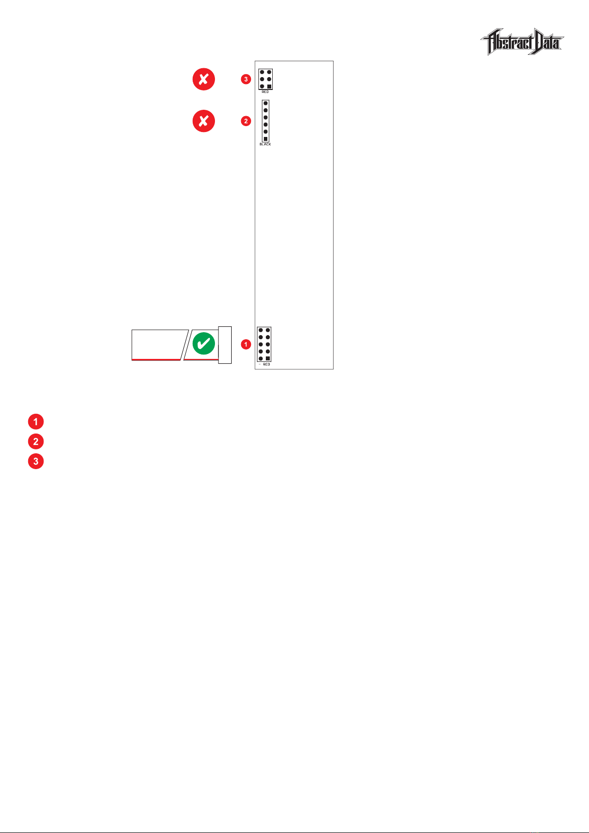
Insert any regular Event signal e.g. a clock, gate, trigger or square-wave/PWM LFO into IN: GATE A1.
Connect the OUT to any source that requires a gate or trigger signal e.g. an envelope generator
set up as part of any basic synth patch.
With no CV inserted – this first algorithm (Global Mode 1/Local Mode 1) will send whatever signal
is at the input, straight to the output with no change.
Click or Double-Click MODE SELECT to cycle through Local Modes 1-6.
Even with no CV inserted – the algorithm for each Local Mode will interpret the input signal differently
and provide a different output pattern from a single input signal.
Click or Double-Click MODE SELECT to return to Local Mode 1.
3) LOCAL MODE CV CONTROL
Insert a non-square LFO into GATE B/CV. As the LFO travels between 0-5V the selected Local Mode
algorithm will start to ‘chop’ into the input signal. The regular input signal is now being output as a pattern.
Changing the LFO wave type or replacing it with a 0-5V CV source at fixed voltage values will both
potentially affect the pattern that is generated by each Local Mode for any given input signal.
3) LOCAL MODE SELECTION VIA CV
Click-Hold the MODE SELECT button until one of the Mode LEDs 1-3 flashes quickly. The module
is now in Button Edit Mode for this button.
Click or Double-Click the MODE SELECT button to cycle through to LED 1. This selects the first
CV option for IN: MODE SELECT. Click-Hold the MODE SELECT button to exit Button Edit Mode.
Select a second, Event signal and insert it into IN: MODE SELECT. This signal will now step through
the Local Modes 1-6 for this Global Mode.
Remove the input at IN: MODE SELECT and repeat the process above for setting the CV options
for IN: MODE SELECT – but this time select LED 2.
Select a non-Square LFO or CV source e.g. an envelope generator and insert it into IN: MODE SELECT.
This 2nd CV option for IN: MODE SELECT will move through the Local Modes according to CV value.
Remove the input at IN: MODE SELECT and click MODE SELECT to return to Local Mode 1.
4) GATE A1/A2 SELECTION VIA CV
Click the GATE A1/A2 SELECT button and it will alternate between IN: GATE A1 and IN: GATE A2.
The algorithm for the selected Local Mode will receive its signal from whatever input is selected.
Click-Hold the GATE A1/A2 SELECT button until one of the A1/A2 LEDs flashes quickly, then click
this button to alternate between the two CV options. Click-Hold GATE A1/A2 SELECT to exit the
Button Edit Mode for this button.
Take the ‘Event’ signal you previously used at IN: MODE SELECT and insert it into IN: GATE A2.
Gate A1/A2 selection can now be controlled via by either of the CV options available for this button.
© 2018 Abstract Data Ltd. Version 1.0.1
4) Quick Start
Page 4 of 13

1) IN: MODE SELECT/COUNT RESET
Mode Select • Use an Event signal e.g. a clock, gate, trigger, square-wave or PWM-type
LFO to cycle through Local Modes or a variable 0-5V CV source to jump
across Local Modes.
Count Reset • Use Event signals to access specific options for each Local Mode.
• See Page 6 for more information on MODE SELECT Button Edit Mode
for setting the CV options for this input.
2) IN: GATE A1/A2 SELECT
Use an Event signal to cycle or jump between IN: GATE A1 and IN: GATE A2.
See Page 6 for more information on GATE A1/A2 SELECT Button Edit Mode for setting the CV
options for this input.
3) IN: GATE A1
Event signal input A1 for all Local Modes.
4) IN: GATE A2
Event signal input A2 for all Local Modes.
5) IN: GATE B/CV
Input B for High (+5V) or Low (0V) signals or CV (0-5V) signals depending on Global Mode.
6) OUT
High (+5V) or Low (0V) output for all Local Modes.
© 2018 Abstract Data Ltd. Version 1.0.1
5) Inputs & Outputs
Page 5 of 13

1) MODE SELECT
Local Mode • Click to cycle forward through Local Modes 1-6.
• Double-Click to cycle backwards through Local Modes 1-6.
Global Mode • Click to cycle forward through Global Modes 1-6.
• Double-Click to cycle backwards through Global Modes 1-6.
Button Edit Mode • Click-Hold until one of the Mode LEDs 1-6 flashes quickly to enter the
Button Edit Mode for this button.
• Click-Hold again until the Mode LED stops flashing to exit the
Button Edit Mode for this button.
2) GATE A1/A2 SELECT
Local Mode • Click to cycle forward between IN: GATE A1 and IN: GATE A2.
• Double-Click to cycle backwards between IN: GATE A1 and IN: GATE A2.
Button Edit Mode • Click-Hold until one of the Mode LEDs 1-6 flashes quickly to enter the
Button Edit Mode for this button.
• Click-Hold again until the Mode LED stops flashing to exit the
Button Edit Mode for this button.
© 2018 Abstract Data Ltd. Version 1.0.1
6) Buttons
Page 6 of 13

MODE OVERVIEW
The Variables mode takes a CV value of 0-5V and converts it to a variable <n> between 1-8.
Each new input Event increments an internal counter that loops upward from1-8. The counter
and the <n> value interact to tell each Local Mode whether to allow particular input Events to ‘pass’
to the output or whether to ‘block’ them. By varying the CV value or the Local Mode or both – many
different patterns can be created from simple input signals.
FIRST PATCH
• This mode is designed to work with most Event and CV types.
• Start with some sort of mid-tempo clock or square-wave LFO and a slow, evolving CV source.
• For each selected Local Mode – as the CV value changes – the Output pattern should also change.
INPUT TYPES
IN: GATE A1 & A2 • Any Event type e.g. clock, gate, trigger, square-wave or PWM-type LFO.
IN: GATE B/CV • Any 0-5V CV type e.g. LFO, envelope generator or variable CV source.
CV OPTIONS
Local • 0-5V CV at IN: GATE B/CV sets each mode’s <n> variable value of 1-8.
Global • Event at IN: MODE SELECT/RESET resets the mode’s <n> count.
LOCAL MODE 1: <nth> Pass
CV • 0-5V CV the variable <n> to a value of: 1 || 2 || 3 || 4 || 5 || 6 || 7 || 8.
Operation • Lets every <nth> of 8 input Events pass to the output.
LOCAL MODE 2: <nth Block>
CV • 0-5V CV sets the variable <n> to a value of: 1 || 2 || 3 || 4 || 5 || 6 || 7 || 8.
Operation • Blocks every <nth> of 8 input Events.
LOCAL MODE 3: <n> Pass
CV • 0-5V CV sets the variable <n> to a value of: 1 || 2 || 3 || 4 || 5 || 6 || 7 || 8.
Operation • Lets only <n> of 8 input Events pass to the output.
LOCAL MODE 4: <n> Block
CV • 0-5V CV sets the variable <n> to a value of: 1 || 2 || 3 || 4 || 5 || 6 || 7 || 8.
Operation • Blocks all <n> of 8 input Events.
LOCAL MODE 5: <n> Pass || <nth> Block
CV • 0-5V CV sets the variable <n> to a value of: 1 || 2 || 3 || 4 || 5 || 6 || 7 || 8.
Operation • Toggles between Local Mode 3 and Local Mode 2.
LOCAL MODE 6: <n> Block || <nth> Pass
CV • 0-5V CV sets the variable <n> to a value of: 1 || 2 || 3 || 4 || 5 || 6 || 7 || 8.
Operation • Toggles between Local Mode 4 and Local Mode 1.
© 2018 Abstract Data Ltd. Version 1.0.1
7) Global Mode 1: Variables
Page 7 of 13

MODE OVERVIEW
The Multiples mode outputs a signal that’s tempo is divided down (slower) or multiplied up (faster)
than the tempo of the input signal. How slow or fast – or how far the tempo is divided down
or multiplied up – is calculated by a combination of the tempo of the input Event, the CV value
and the selected Local Mode.
FIRST PATCH
• This mode works best with regular Event inputs like clocks - but will also work with patterns and
Event inputs with irregular timing.
• Start with some sort of mid-tempo clock or square-wave LFO and a manually adjustable CV source.
• For each selected Local Mode – as the CV value changes – the Output clock division/multiple should
also change.
INPUT TYPES
IN: GATE A1 & A2 • Any Event type e.g. clock, gate, trigger, square-wave or PWM-type LFO.
IN: GATE B/CV • Any 0-5V CV type e.g. LFO, envelope generator or variable CV source.
CV OPTIONS
Local • 0-5V CV at IN: GATE B/CV sets each mode’s <n> divisor or multiplier value.
Global • Event at IN: MODE SELECT/RESET sets each mode’s phase/cycle length
• Mark/Time calculations are still taken from IN: GATE A1 & A2.
LOCAL MODE 1: Divide /1
CV • 0-5V CV sets the divider <n> to a value of: 1 || 2 || 3 || 4 || 5.
Operation • The output frequency is the input frequency divided by <n>.
LOCAL MODE 2: Multiply /1
CV • 0-5V CV sets the multiplier <n> to a value of: 1 || 2 || 3 || 4 || 5.
Operation • The output frequency is the input frequency multiplied by <n>.
LOCAL MODE 3: Divide /2
CV • 0-5V CV sets the divider <n> to a value of: 1 || 2 || 4 || 6 || 8.
Operation • The output frequency is the input frequency divided by <n>.
LOCAL MODE 4: Multiply /2
CV • 0-5V CV sets the multiplier <n> to a value of: 1 || 2 || 4 || 6 || 8.
Operation • The output frequency is the input frequency multiplied by <n>.
LOCAL MODE 5: Divide /3
CV • 0-5V CV sets the divider <n> to a value of: 1 || 3 || 6 || 9 || 12.
Operation • The output frequency is the input frequency divided by <n>.
LOCAL MODE 6: Multiply /3
CV • 0-5V CV sets the multiplier <n> to a value of: 1 || 3 || 6 || 9 || 12.
Operation • The output frequency is the input frequency multiplied by <n>.
© 2018 Abstract Data Ltd. Version 1.0.1
8) Global Mode 2: Multiples
Page 8 of 13

MODE OVERVIEW
The Probability mode is a set of pseudo-random and percentage chance-based algorithms.
Whether or not an input Event appears at the Output – or in what form it appears – is decided on by
‘chance’. For this mode – ‘chance’ is a percentage betwen 0% (definitely will not happen) and 100%
(definitely will happen) that is set by a CV value of between 0-5V.
FIRST PATCH
• This mode is designed to work with most Event and CV types.
• Start with some sort of mid-tempo clock or square-wave LFO and a slow, evolving CV source.
• For each selected Local Mode – as the CV value changes – the Output pattern should also change.
INPUT TYPES
IN: GATE A1 & A2 • Any Event type e.g. clock, gate, trigger, square-wave or PWM-type LFO.
IN: GATE B/CV • Any 0-5V CV type e.g. LFO, envelope generator or variable CV source.
CV OPTIONS
Local • 0-5V CV at IN: GATE B/CV sets each mode’s probability or percentage chance.
Global • High Event at IN: MODE SELECT/RESET holds the last recorded CV value
• Any new CV values at IN: GATE B/CV are ignored.
LOCAL MODE 1: Percentage Pass
CV • 0-5V CV sets the probability percentage from 0-100%.
Operation • The percentage chance that an input Event passes to the output.
LOCAL MODE 2: Percentage Block
CV • 0-5V CV sets the probability percentage from 0-100%.
Operation • The percentage chance that an input Event is blocked.
LOCAL MODE 3: Gate Tie
CV • 0-5V CV sets the probability percentage from 0-100%.
Operation • The percentage chance that an input Event will be tied to the next input Event.
LOCAL MODE 4: Gate Tie/Pass
CV • 0-5V CV sets the probability percentage from 0-100%.
Operation • The percentage chance that an input Event will be tied to the next input Event.
• Only Events that have been ‘tied’ to other Events are passed to the output.
LOCAL MODE 5: Flip-Flop (Coin Toss)
CV • 0-5V CV sets the probability percentage from 0-100%.
Operation • Each input Event is read as a ‘coin toss’.
• Whether the Event is ‘tossed’ or not is set by the CV probability percentage.
• An Event that is ‘tossed’ has a 50/50 chance it will ‘land’ High or Low.
LOCAL MODE 6: Flip-Flop (Inversion)
CV • 0-5V CV sets the probability percentage from 0-100%.
Operation • The percentage chance that an input Event will be inverted at the output.
© 2018 Abstract Data Ltd. Version 1.0.1
9) Global Mode 3: Probability
Page 9 of 13

MODE OVERVIEW
The Logic mode is based on the three archetypal logic types and their inverted pairs. Logic functions
are one of the earliest and best examples of using ‘maths’ to make rhythms in electronic music.
Please note – you don’t need to understand the maths or the origins of the logic types in order to
use them – they are great to experiment with.
FIRST PATCH
• This mode is designed to work with most Event and CV types.
• Start with any two mid-tempo clocks or square-wave LFOs.
• For each selected Local Mode – as either of the input signals change – the Output pattern should
also change.
INPUT TYPES
IN: GATE A1 & A2 • Any Event type e.g. clock, gate, trigger, square-wave or PWM-type LFO.
IN: GATE B/CV • Any Event type e.g. clock, gate, trigger, square-wave or PWM-type LFO.
CV OPTIONS
Local • IN: GATE B/CV is the second Logic input as per standard 2x input Logic.
Global • High Event at IN: MODE SELECT/RESET ‘mutes’ the output.
• Any new Events at IN: GATE A1 & A2 or IN: GATE B/CV are ignored.
LOCAL MODE 1: AND
CV • Standard 2x input Boolean Logic.
Operation • Input ‘A’ can be switched between A1 and A2 - manually or via CV.
LOCAL MODE 2: NAND
CV • Standard 2x input Boolean Logic.
Operation • Input ‘A’ can be switched between A1 and A2 - manually or via CV.
LOCAL MODE 3: OR
CV • Standard 2x input Boolean Logic.
Operation • Input ‘A’ can be switched between A1 and A2 - manually or via CV.
LOCAL MODE 4: NOR
CV • Standard 2x input Boolean Logic.
Operation • Input ‘A’ can be switched between A1 and A2 - manually or via CV.
LOCAL MODE 5: XOR
CV • Standard 2x input Boolean Logic.
Operation • Input ‘A’ can be switched between A1 and A2 - manually or via CV.
LOCAL MODE 6: XNOR
CV • Standard 2x input Boolean Logic.
Operation • Input ‘A’ can be switched between A1 and A2 - manually or via CV.
© 2018 Abstract Data Ltd. Version 1.0.1
10) Global Mode 4: Logic
Page 10 of 13

MODE OVERVIEW
The Phase mode allows a user to shift the starting point or adjust the ‘mark/space’ ratio of an input
Event to a later starting point or to a different ratio. This is all done via CV and depending on the
selected Local Mode - the starting point shift or the mark/space ratio change can be based on a
‘musical’ sub division, a percentage shift or a time-based delay in mS.
FIRST PATCH
• This mode works best with regular Event inputs like clocks - but will also work with patterns and
Event inputs with irregular timing.
• Start with some sort of mid-tempo clock or square-wave LFO and a manually adjustable CV source.
• For each selected Local Mode – as the CV value changes – the Output phase should also change.
INPUT TYPES
IN: GATE A1 & A2 • Any Event type e.g. clock, gate, trigger, square-wave or PWM-type LFO.
IN: GATE B/CV • Any 0-5V CV type e.g. LFO, envelope generator or variable CV source.
CV OPTIONS
Local • 0-5V CV at IN: GATE B/CV sets each mode’s phase-offset or delay.
Global • Event at IN: MODE SELECT/RESET sets each mode’s phase/cycle length.
• Mark/Time calculations are still taken from IN: GATE A1 & A2.
LOCAL MODE 1: Quantised Shift
CV • 0-5V CV sets the phase shift <n> to a value of:
0 || 1/16 || 1/8 || 1/4 || 1/3 || 1/2 || 3/4 || 1.
Operation • Phase-shifts an input Event by a sub-division of it’s own tempo.
LOCAL MODE 2: Percentage Shift
CV • 0-5V CV sets the phase shift value from 0-100%.
Operation • Phase-shifts an input Event by a percentage of it’s own tempo.
LOCAL MODE 3: Short Shift
CV • 0-5V CV sets the phase shift value from 0-1600mS.
Operation • Phase-shifts an input Event by a time in mS.
LOCAL MODE 4: Long Shift
CV • 0-5V CV sets the phase shift value from 0-4800mS.
Operation • Phase-shifts an input Event by a time in mS.
LOCAL MODE 5: Quantised Mark/Space
CV • 0-5V CV sets the phase shift <n> to a value of:
Pulse || 12.5/87.5 || 25/75 || 37.5/62.5 || 50/50 || 62.5/37.5 || 75/25 || 87.5/12.5.
Operation • Adjusts the Mark/Space ratio of an input Event to become a sub-division
ratio of it’s own tempo.
LOCAL MODE 6: Percentage Mark/Space
CV • 0-5V CV sets the Mark segment of the Mark/Space ratio from 0-100%.
Operation • Adjusts the Mark/Space ratio of an input Event to become a percentage
ratio of it’s own tempo.
© 2018 Abstract Data Ltd. Version 1.0.1
11) Global Mode 5: Phase
Page 11 of 13

MODE OVERVIEW
The Gates mode allows a user to take Event signals like gates and triggers and extend their length
or join multiple Events together to form different length gate Events from
FIRST PATCH
• This mode is designed to work with most Event and CV types.
• Start with some sort of mid-tempo clock or square-wave LFO and a slow, evolving CV source.
• For each selected Local Mode – as the CV value changes – the Output pattern should also change.
INPUT TYPES
IN: GATE A1 & A2 • Any Event type e.g. clock, gate, trigger, square-wave or PWM-type LFO.
IN: GATE B/CV • Any 0-5V CV type e.g. LFO, envelope generator or variable CV source.
CV OPTIONS
Local • 0-5V CV at IN: GATE B/CV sets each mode’s <n> value or Logic threshold.
Global • Event at IN: MODE SELECT/RESET resets the mode’s <n> count.
LOCAL MODE 1: <n> High
CV • 0-5V CV sets a variable value of <n> to 1/2/3/4/5/6/7/8.
Operation • Output stays High for <n> of 8 Events.
LOCAL MODE 2: <n> High/Low
CV • 0-5V CV sets a variable value of <n> to 1/2/3/4/5/6/7/8.
Operation • Output stays High for <n> of 8 Events then Low for <n> of 8 Events.
LOCAL MODE 3: Logic Pass
CV • 0-5V CV sets the Logic threshold above or below +2.5V.
Operation • Reads CV at each new input Event.
• Output goes High if input is High AND CV >2.5V.
• Output goes Low if input is Low AND/OR CV <2.5V.
LOCAL MODE 4: Logic Hold
CV • 0-5V CV sets the Logic threshold above or below +2.5V.
Operation • Reads CV at each new input Event.
• Output goes High if CV >2.5V.
• Output goes Low if CV >2.5V.
LOCAL MODE 5: <n> High/High/Low
CV • 0-5V CV sets a variable value of <n> to 1/2/3/4/5/6/7/8.
Operation • Toggles between Local Mode 1 and Local Mode 2.
LOCAL MODE 6: Logic Pass/Hold
CV • 0-5V CV sets a variable value of <n> to 1/2/3/4/5/6/7/8.
Operation • Toggles between Local Mode 3 and Local Mode 4.
© 2018 Abstract Data Ltd. Version 1.0.1
12) Global Mode 6: Gates
Page 12 of 13

HARDWARE: Controls (Buttons): Mode Select: Global Mode
Local Mode
Button Edit Mode
Gate A1/A2 Select: Gate A1/A2
Button Edit Mode
Inputs (Event): A1: 0 to +5V Event
A2: 0 to +5V Event
Inputs (Event/CV): B (Event): 0 to +5V CV
B (CV): 0 to +5V CV
Outputs (Signal): Out: 0 to +5V Event
Power Requirements: +/-12V: 10-16-pin IDC connector
Current Draw: +12V: Approx. 53mA average
-12V: Approx. 35mA average
+5V: NA
Dimensions: Width: 6HP
Depth: 28mm [Panel to IDC connector]
Supplied Accessories: Cable: 1x 10-16-pin, IDC
Screws: 2x M3
CREDITS: Firmware Development: Paul Soulsby
Beta Testing: Radek Rudnicki
Thanks: Nigel Christopher
Richard Devine
Chris Meyer
Alex Theakston
Ben Wilson
CONTACT: Justin Owen @ Abstract Data
www.abstractdata.biz
facebook.com/abstractdatabiz
twitter.com/abstractdatabiz
instagram.com/abstractdatabiz
soundcloud.com/abstractdatabiz
youtube.com/abstractdatabiz
13) Specs
Page 13 of 13
© 2018 Abstract Data Ltd. Version 1.0.1
Table of contents
Other Abstract Data Control Unit manuals
Popular Control Unit manuals by other brands

Acclaim Lighting
Acclaim Lighting AL Driver series user guide

FIRELINX
FIRELINX Generation 3 manual

Panasonic
Panasonic INDUSTRY PAN9028 quick start guide

urmet domus
urmet domus 1083 Installation booklet

Dakota Digital
Dakota Digital BIM-01-2-HSN2 quick start guide

Bradley
Bradley S59-5000 Series Installation