Abus TVIP21502 User manual

64
IR HD 720p Pan/Tilt
Network Camera
User manual
Version 11/2012

65
Introduction
Dear Customer,
Thank you for purchasing this product.
This product meets the requirements of the applicable European and national guidelines.
The corresponding declarations and documents can be obtained from the manufacturer.
To maintain this condition and to ensure risk-free operation, you as the user must observe these
operation instructions!
Before initial start-up, read through the complete operating instructions observing operating and
safety instructions.
All company and product names mentioned in this document are registered trademarks.
All rights reserved.
If you have any questions, please contact your installer or your local dealer!
Disclaimer
This user manual was prepared with greatest care. If you should notice omissions or inaccuracies,
please inform us about these on the back of this manual given address.
The ABUS Security-Center GmbH & Co. KG assumes no liability for technical and typographical
faults and reserves the right to make at any time modifications to the product or user manual
without a previous announcement.
The company is not liable or responsible for direct and indirect subsequent damages which are
caused in connection with the equipment, the performance and the use of this product.
No guarantee for the content of this document is taken.

66
Important safety instructions
The warranty will expire for damage due to non-compliance with these operating
instructions. We shall not be liable for any consequential loss!
We do not accept liability for damage to property or personal injury caused by incorrect
handling or non-compliance with the safety-instructions. In such cases the warranty will
expire.
Dear customer,
The following safety instructions are intended not only for the protection of your health, but also for
the protection of the device. Please read through the following points carefully:
There are no parts on the inside of the product which need to be serviced. Apart from this, the license
(CE) and the guarantee/warranty will lapse if you open/take the product apart.
The product will be damaged even it falls from a low height.
This device can be used in inside only.
During the installation of the camera please take care that direct sunlight cannot fall onto the image
sensor of the device. Please follow the installation instructions in the corresponding chapter of this
user manual.
Avoid using the device under the following unfavorable ambient conditions:
wetness or excessive air humidity
extreme cold or heat
direct sunlight
dust or combustible gases, vapors or solvents
strong vibration
strong magnetic fields, such as those found in the vicinity of machinery or loudspeakers
the camera should not positioned with opened iris towards the sun - this can lead to the
destruction of the sensor.
the camera may not be installed on unstable surfaces
General safety instructions:
Do not leave packaging material lying around carelessly. Plastic/ foil/bags and polystyrene parts etc.
could become dangerous toys for children.
For safety reasons don’t give the camera into child hands due to them being able to swallow small
parts.
Please do not insert objects through the openings into the device.
Use only accessories which are specified by the manufacturer.
Please do not connect incompatible parts to the device.
Please pay attention to the safety instructions and user manuals of the other connected devices.
Check the device for damages before installation. If this should be the case please do not use it.
Please adhere to the operational voltage limitations listed in the technical data. High voltage could
destroy the device and pose a health hazard (electric shock).
During the installation into an existing video surveillance system make sure that all devices are
disconnected from the low and supply voltage circuit.
If in doubt allow a professional electrician to mount, install and wire-up your device. Improper or
make-do electrical connection to the mains does only represent at threat to you but also to other
persons.
Wire-up the entire system making sure that the mains and low voltage circuit remain separated
and cannot come into contact with each other in normal use or due to any malfunctioning.

67
Contents
1. Usage in accordance with regulations ...............................................................................69
2. Scope of delivery..................................................................................................................69
3. Installation.............................................................................................................................70
3.1 Power supply ........................................................................................................................70
3.2 Installing the camera............................................................................................................70
4. Camera description ..............................................................................................................70
4.1 Description of connectors ...................................................................................................70
4.2 Status LEDs...........................................................................................................................71
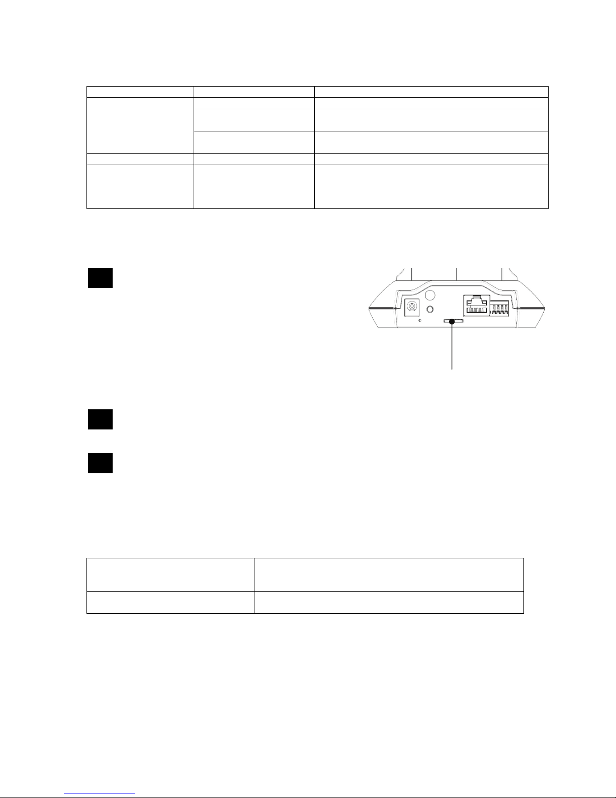
4.3 Using the microSD slot ........................................................................................................71
4.4 Restoring the factory settings.............................................................................................71
4.5 Alarm input and output ........................................................................................................72
4.6 Putting into operation ..........................................................................................................73
4.7 Accessing the network camera for the first time...............................................................74
4.8 Accessing the network camera over a web browser.........................................................75
4.9 Installing the ActiveX plug-in ..............................................................................................75
4.10 Adjusting the security settings ...........................................................................................75
4.11 Password prompt .................................................................................................................76
4.12 Accessing the network camera over an RTSP player.......................................................76
4.13 Accessing the network camera over a mobile phone.......................................................77
4.14 Accessing the network camera over ABUS VMS...............................................................78
5. User functions.......................................................................................................................79
Video control.................................................................................................................................82
6. Camera settings (configuration) .........................................................................................84
6.1 System...................................................................................................................................85
6.2 Camera...................................................................................................................................88
6.3 Playback ................................................................................................................................92
6.4 Network..................................................................................................................................94
6.5 Security................................................................................................................................102
6.6 PT (Pan/Tilt).........................................................................................................................104
6.7 Event....................................................................................................................................107
6.6.1 Event server..........................................................................................................107
6.6.2 Event recording.....................................................................................................110
6.6.3 Continuous Recording...........................................................................................112
5.1 Switching input and switching output..............................................................................113
6.8 Motion detection.................................................................................................................113

68
6.9 Schedule..............................................................................................................................114
6.10 Audio detection...................................................................................................................114
6.11 System log...........................................................................................................................115
7. Maintenance and cleaning.................................................................................................116
7.1 Function test .......................................................................................................................116
7.2 Cleaning...............................................................................................................................116
8. Disposal...............................................................................................................................116
9. Technical data.....................................................................................................................117
10. GPL license information ....................................................................................................119

69
1. Usage in accordance with regulations
Use of this product for other than the described purpose may lead to damage to the product
and other dangers. All other uses are not in accordance with regulations, and result in the
invalidation of the product guarantee and warranty. No liability can be accepted as a result.
This also applies to any alterations or modifications made to the product.
Read the entire operating manual carefully before putting the product into operation. The
operating manual contains important information on installation and operation.
2. Scope of delivery
ABUS network camera
TVIP21502 / TVIP21552 / TVIP22500
Power supply unit
Wall mount bracket
Network cable (1 metre)
Software CD
(including operating manual)
Antenna
(TVIP21552)
Quick guide

70
3. Installation
Make sure that all accessories and parts listed above are present in the scope of delivery. An Ethernet cable
is required for camera operation. This Ethernet cable must meet UTP Category 5 (CAT 5) specifications and
must not be longer than 100 metres.
3.1 Power supply
Before starting installation, ensure that the mains voltage and the rated voltage on the power supply unit are
identical. The camera’s supply voltage is 12 VDC. Please use the supplied power supply
3.2Installing the camera
With the camera a mounting bracket is supplied. At the backside of the camera a socket is located. Using this
socket the camera mounting bracket can be fixed at the camera. The mounting bracket can be fixed at the
wall unsing the supplied pegs and screws.
4. Camera description
4.1Description of connectors
Power
connector
Reset
Ethernet
connecto
r
Alarm input/output
WLAN Antenna
(TVIP21552)
Lens
Integrated
microphone
Micro
SD card
WPS
button Power LED Network LED

71
4.2Status LEDs
LED Color Description
Network info LED Off Network cable not connected or wireless mode
purple / blue flashing
(high frequent) Start-up procedure
Blue flashing (high
frequent) Start-up procedure finished, normal working mode
Status info LED Red on continuousely Start-up procedure
Blue on continuousely IP address successfully assigned (Note: On manual
setup of IP address, a wrong IP address can be
applied. In this case the blue LED is continuously on
as well)
4.3Using the microSD slot
Disconnect the power supply before inserting the
microSD card.
The microSD card can only be inserted into the socket in a
certain position. Use a narrow pointed object (such as a flat
narrow screwdriver) to insert it. When it is correctly positioned,
the card is flush with the housing surface and does not
protrude.
The card is detected by the camera when the power supply is
reconnected, and can then be used as desired.
The microSD card cannot be replaced when the system
is in operation!
To use the microSD card function, an active Internet
connection that makes the correct time available to the camera
after a restart is required (NTP function).
4.4Restoring the factory settings
Camera restart Press the button until the blue LED goes out -> constantly red
during camera restart -> constantly blue after successful
camera restart
Restoring the factory settings Press the button until the LED lights up blue constantly ->
constantly blue after successful camera restart
MicroSD card slot

72
4.5Alarm input and output
Connection Description Max. load (V/A)
DO - alarm output Connection of a transistor or relay:
Transistor: NPN with emitter
against ground (GND)
Relay: 12 V DC “AND”
connection, plus DO with diode
(see example below)
24 V DC, 100 mA
DI - alarm input Activation of the alarm input by
connecting the DI and GND
connections
-
GND Ground -
12 V DC Voltage output 12 V DC, max. 100 mA

73
4.6Putting into operation
The network camera automatically detects whether a direct connection between the PC and camera should
be made. A cross-over network cable is not required for this. You can use the supplied patch cable for direct
connection when putting into operation for the first time.
Direct connection of the network camera to a PC / laptop
1. Ensure that a CAT 5 network cable is used.
2. Connect the cable to the Ethernet interface of the PC / laptop and the network camera.
3. Connect the power supply to the network camera.
4. Configure the network interface of your PC / laptop to the IP address 192.168.1.1 and the default
gateway to 192.168.1.2.
5. Go to point 4.6 to finish the initial set-up and establish the connection to the network camera.
Connecting the network camera to a router / switch
1. Ensure that a CAT 5 network cable is used.
2. Connect the PC / laptop to the router / switch.
3. Connect the network camera to the router / switch.
4. Connect the power supply to the network camera.
5. If a DHCP server is available in your network, set the network interface of your PC / laptop to
“Obtain an IP address automatically”.
6. If no DHCP server is available, configure the network interface of your PC / laptop to 192.168.1.1
and the default gateway to 192.168.1.2.
7. Go to point 4.6 to finish the initial set-up and establish the connection to the network camera.
8.
CAT 5 Ethernet cable
Internet

74
4.7Accessing the network camera for the first time
The network camera is accessed for the first time using the IP Installer.
After the installation wizard is started, it searches for all connected EyseoIP network cameras and video
servers in your network.
The program is found on the supplied CD-ROM. Install the program on your PC and then run it.
If a DHCP server is available in your network, the IP address is assigned automatically for both the PC /
laptop and the network camera.
If no DHCP server is available, the network camera determines a free IP address from the 192.168.1.2–
192.168.1.254 range independently. Your PC system must be located in the same IP segment in order to
establish communications with the network camera.
The standard setting for the network camera is “DHCP”. If no DHCP server is in operation in
your network, then we recommend setting the IP address manually to a fixed value following
initial access to the network camera.

75
4.8Accessing the network camera over a web browser
When you first access the network camera under Windows, the web browser queries the installation of an
ActiveX plug-in for the network camera. This query depends on the Internet security settings of your PC. If the
highest security level is set, the PC will refuse any installation and any attempt at running it. This plug-in is
used for displaying the video in the browser. To continue, click “Install”. If the web browser prevents the
installation, open the Internet security settings and reduce the security level or consult your IT or network
administrator.
4.9Installing the ActiveX plug-in
If Mozilla Firefox is used as the browser when accessing the camera, an MJPEG stream is
provided by the camera instead of the ActiveX plug-in.
4.10 Adjusting the security settings
Note: Your PC security settings may prevent a video stream. You can change the security
settings to a lower level under “Tools / Internet Options / Security”. Make sure you enable
ActiveX controls and downloads.

76
4.11 Password prompt
An administrator password is defined in the network camera as standard. However, the administrator should
define a new password immediately for security reasons. After the new administrator password is stored, the
network camera asks for the user name and password every time it is accessed.
The administrator account is set up in the factory as follows: user name “admin” and password “12345”. Each
time the network camera is accessed, the browser displays an authentication window and asks for the user
name and password. If you can no longer access your personal settings in the administrator account, you can
log in again with user name “admin” and password “12345” after resetting the network camera to the factory
settings.
To enter a user name and password, proceed as follows:
Open Internet Explorer and enter the IP address of the camera (e.g. “http://192.168.1.14”).
You are then prompted for authentication:
-> You are now connected with the network camera and can see a video stream.
4.12 Accessing the network camera over an RTSP player
You have the possibility of accessing the MPEG-4 / H.264 data streams on the network camera with an
RTSP-compatible media player. The following free media players support RTSP:
VLC Media Player
Real Player
Quicktime Media Player
The address format for entering the connection data is as follows:
rtsp://<IP address of the network camera>:<RTSP port>/<Type of video data stream>
Example:
rtsp://192.168.1.14:554/video.mjpg (MJPEG stream)
rtsp://192.168.1.14:554/video.mp4 (MPEG-4 stream)
rtsp://192.168.1.14:554/video.h264 (H.264 stream)
Standard user name: admin
Standard password: 12345

77
4.13 Accessing the network camera over a mobile phone
Ensure that you can establish an Internet connection over your mobile phone. Your mobile phone must also
be equipped with an RTSP-compatible media player. The following media players for mobile phones support
RTSP:
Real Player
Core Player
Please note that access to the network camera via mobile phone is restricted due to the reduced network
bandwidth available. We therefore recommend making the following video stream settings in order to reduce
the data quantity:
Video compression MPEG-4
Resolution 160x120
Frame rate 5 frames / second
Video quality (constant bit rate) 48 kbps
If your media player does not support RTSP authentication, then deactivate the authentication mode for RTSP
in the network camera configuration settings.
The address format for entering the connection data is as follows:
rtsp://<IP address of the network camera>:<RTSP port>/<Type of video data stream>
Example:
rtsp://192.168.1.14:554/video.3gp

78
4.14 Accessing the network camera over ABUS VMS
The free ABUS VMS Express recording software can be found on the supplied CD-ROM. You then have the
possibility of connecting and recording several ABUS Security Center network cameras on one interface.
Further information can be found in the software manual on the enclosed CD-ROM.

79
5. User functions
Open the main menu on the network camera. The interface is divided into the following main areas:
Live image display
You can access the full-screen view by double-clicking here (with Internet Explorer only).
Camera settings
Settings (configuration)
Used to configure the camera (administrator settings)
Live options
Mode: Choose the compression type for transmission of the live image.
View size: Select a view size.
Auto: Automatic adjustment to the screen size
Original size: Display of the video image in accordance with the set camera resolution (e.g.
1280x720).
Note: The view size specified here relates to the live image shown in the display mode of the
browser. The resolution set in the camera is always transmitted, even when the view size set
here is smaller.
Live image
display Camera settings
Video control

80
Protocol: Allows you to select a transmission protocol for data transfer between the client and the server. The
following protocol options are available for optimizing the application: UDP, TCP, HTTP.
The UDP protocol gives you a larger number of real-time video streams. However, some data packets can be
lost due to the large data volume in the network. Pictures may be unclear in this case. The UDP protocol is
recommended if you have no special requirements.
With the TCP protocol, fewer data packets are lost and the video display is more accurate. However, the
disadvantage of this protocol is that the video stream is transmitted at a lower frame rate than the UDP
protocol.
Use the HTTP protocol if the network is protected by a firewall and only the HTTP port (80) is available.
The selection of the protocol is recommended to be made in the following order: UDP – TCP – HTTP
This function is only available when using Internet Explorer.
Video buffer: Activate the video buffer if your line has low bandwidth. Image data is saved temporarily in the
network camera for clearer transmission, meaning the image delay is increased.
This function is only available when using Internet Explorer.
PT control
Use the control buttons for pan/tilt control on the camera.
Arrows:
The pan/tilt head is moved by clicking the button
in the corresponding direction
Home:
The image is moved to the home position
Preset Go:
Select one of the preset positions from the list. The
network camera accesses the position immediately.
Set:
The current camera position in the live image is
saved as a preset. Presets saved in this way all have
a generic file name (Preset1, Preset2 etc.).
Patrol:
Select which tour should be started. Tours 1 to 4 can
be changed in the camera settings.
Go:
Starts the selected tour.
Pan speed:
Select a value between 0 and 100. Higher values
result in quicker movements.

81
Tilt speed:
Select a value between 0 and 100. Higher values
result in quicker movements.
Auto Pan speed:
This setting is used during a tour.
Select a value between 0 and 100. Higher values
result in quicker movements.
Endless mode
This mode is optimized for controlling the network camera over the local network (LAN).
Sequence mode
This mode is optimized for controlling the network camera over the Internet. The step size of the pan/tilt control
is limited to a short step size.

82
Video control
These functions are only available when using Internet Explorer.
Snapshot
The web browser displays a new window containing the snapshot. To save the snapshot, either left-click it
and then click the floppy disk icon or right-click it and select “Save” from the context menu.
Full-screen view
Activate the full-screen view. The live image on the network camera is shown on the entire screen.
Start/stop live image display
The live stream can be stopped or ended. In both cases you can continue the live stream by pressing the play
symbol.
Local recording
A recording on the local hard drive can be started or stopped. If you click the button, the Windows “Save as”
dialog is called up.
Select a target directory on your hard drive. A directory and recording file are created automatically in the
folder under the following name:
YYYYMMDD
YYYYMMDDHHmmss.avi
Y = Year
M = Month
D = Day
H = Hour
m = Minute
s = Second

83
Example:
C:\Recording\20091215\20091215143010.avi
The recorded data can be played back using an MP4-compatible video player (e.g. VLC Media
Player). Alternatively, you can also watch the videos on Windows Media Player by installing a
video codec in the IP Installer.
Digital zoom
Click the magnifying glass symbol to activate the digital zoom. The zoom factor can be changed on the scroll
bar.
Setting the zoom factor
Change the zoom factor by moving the bar from left (low zoom) to right (high zoom).
Other manuals for TVIP21502
1
This manual suits for next models
2
Table of contents
Other Abus IP Camera manuals

Abus
Abus TVIP71501 User manual

Abus
Abus TVIP62000 User manual

Abus
Abus eyseo TV7144 User manual

Abus
Abus TVHD50000 User manual

Abus
Abus TVAC19000A User manual

Abus
Abus TVIP11561 User manual

Abus
Abus TVIP52502 User manual

Abus
Abus TVIP70000 User manual

Abus
Abus TVVR11000 User manual

Abus
Abus IPCB42500 User manual

Abus
Abus TVIP51500 User manual

Abus
Abus TVAC16010B User manual

Abus
Abus TVAC16010C User manual

Abus
Abus TVAC15000 User manual

Abus
Abus TVHD60000 User manual

Abus
Abus PPIC90000 User manual

Abus
Abus TVIP21502 User manual

Abus
Abus PPIC90000 User manual

Abus
Abus TVIP41560 User manual

Abus
Abus TVAC19100A User manual