Accelleran E1000 Series Setup guide

© 2018 Accelleran N.V. all rights reserved.
Accelleran and the Accelleran logo are trademarks of Accelleran N.V.
All other trademarks are the property of their respective owners.
E1000 Series
LTE Base Station
Safety and Installation
Instructions

E1000 Series Safety and Installation Instructions
SI-00101 v2 2
Table of Contents
Introduction......................................................................................................... 3
Intended Use ....................................................................................................... 4
Safety ................................................................................................................. 4
General........................................................................................................ 4
Federal Communication Commission Interference Statement ........................... 5
Professional installation instruction................................................................ 6
Power Supply...................................................................................................... 7
Radio Spectrum................................................................................................... 7
Technical Specification ........................................................................................ 8
All E1000 Series Models............................................................................... 8
Model E1010 ............................................................................................... 8
Model E1011 ............................................................................................... 8
Model E1012 ............................................................................................... 8
Technical Description .......................................................................................... 9
End to End Connectivity ............................................................................... 9
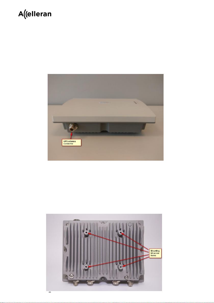
External Ports............................................................................................... 9
Mounting Points......................................................................................... 10
Lightning protection earthing point .............................................................. 11
LTE Antennas............................................................................................ 11
Accessories................................................................................................ 11
Installation ........................................................................................................ 13
Installing the E10xx on a mounting pole....................................................... 13
Grounding the E10xx.................................................................................. 14
Install the LTE antennas.............................................................................. 16
Install the GNSS antenna............................................................................. 16
Seal the RF connectors................................................................................ 17
Connect the backhaul and power.................................................................. 17
Check LED indicators................................................................................. 18
Power indicator...................................................................................18
Network indicator................................................................................18

E1000 Series Safety and Installation Instructions
SI-00101 v2 3
Sync indicator..................................................................................... 19
User indicator ..................................................................................... 19
LTE Indicator ..................................................................................... 19
Introduction
This document contains safety and installation instructions for the Accelleran
E1000 Series LTE Base Station (eNodeB), shown in Figure 1.
The E1000 series includes several different models, each designed for use on
a different frequency band or set of bands. For example, model E1010
operates on LTE band 42, E1011 operates on LTE band 43, E1012 operates
on LTE band 48. In the rest of this document, the name E10xx is used to mean
any model in the E1000 series.
The remainder of this document applies to all E1000 series models, except that
in the Technical Description section there is a sub-section for each individual
model giving its frequency bands and maximum transmit power.
Detailed guidance on configuring the E10xx and monitoring its status and
performance can be found in documentation available separately from
Accelleran.
Figure 1 - E1000 Series LTE Base Station

E1000 Series Safety and Installation Instructions
SI-00101 v2 4
Intended Use
The product is intended for use as a base station (eNodeB) in an LTE network.
It is designed to be installed outdoors but may also be installed indoors. It is not
to be sold to, installed by or operated by the general public.
Safety
General
The product must only be used for its intended purpose.
The product and antennas must be installed, serviced and replaced only by
trained and qualified personnel who are familiar with safe working practices,
local building and safety codes and, where applicable, are licensed by the
appropriate regulatory authorities.
The product must be securely fixed to a suitable structure such as a wall, a
building or a tower designed for the purpose. If a mounting pole is used, it must
be securely fixed to the building or tower before the product is fixed to it.
The product must be fixed in position using fixings that can safely bear the
weight of the product (including antennas if connected directly to the product).
The product must be installed in a position where there is minimal risk of a
person accidentally colliding with it or its antennas.
LTE antennas must be installed in a position such that the distance from them
to any person will always be at least 20 cm while the product is transmitting.
The product must be securely fixed in position before power is applied.
If installed outdoors, the product must be protected against lightning strike by
connecting it to earth using a suitable conductor.
Since E1012/CBRS is a Category A device the product can only be installed
outdoors below 6m height AGL or indoors.
The supplied Power over Ethernet Plus (PoE+) injector must be installed in an
indoor environment or in a weather-proof enclosure.

E1000 Series Safety and Installation Instructions
SI-00101 v2 5
Federal Communication Commission Interference
Statement
This equipment has been tested and found to comply with the limits for a Class
B digital device, pursuant to Part 15 of the FCC Rules. These limits are
designed to provide reasonable protection against harmful interference in a
residential installation. This equipment generates, uses and can radiate radio
frequency energy and, if not installed and used in accordance with the
instructions, may cause harmful interference to radio communications.
However, there is no guarantee that interference will not occur in a installation.
If this equipment does cause harmful interference to radio or television
reception, which can be determined by turning the equipment off and on, the
user is encouraged to try to correct the interference by one of the following
measures:
•Reorient or relocate the receiving antenna.
•Increase the separation between the equipment and receiver.
•Connect the equipment into an outlet on a circuit different from that to
which the receiver is connected.
•Consult the dealer or an experienced radio/TV technician for help.
FCC Caution: Any changes or modifications not expressly approved by the
party responsible for compliance could void the user's authority to operate this
equipment.
This device complies with Part 15 of the FCC Rules. Operation is subject to the
following two conditions: (1) This device may not cause harmful interference,
and (2) this device must accept any interference received, including
interference that may cause undesired operation.
IMPORTANT NOTE:
FCC Radiation Exposure Statement:
This equipment complies with FCC radiation exposure limits set forth for an
uncontrolled environment. This equipment should be installed and operated
with minimum distance 20 cm between the radiator & your body.
This transmitter must not be co-located or operating in conjunction with any
other antenna or transmitter.

E1000 Series Safety and Installation Instructions
SI-00101 v2 6
Professional installation instruction
The product will be distributed through controlled distribution channel and
installed by trained professional and will not be sold directly to the general
public through retail store.
1. Installation personnel
This product is designed for specific application and needs to be installed by
qualified personnel who has RF and related rule knowledge. The general user
shall not attempt to install or change the setting.
2. Installation location
The product shall be installed at a location where the radiating antenna can be
kept 20 cm from nearby person in normal operation condition to meet
regulatory RF exposure requirement.
3. External antenna
Use only the antennas which have been approved by Gemtek, Accelleran. The
non-approved antenna(s) may produce unwanted spurious or excessive RF
transmitting power which may lead to the violation of FCC limit and is
prohibited.
4. Installation procedure
Please refer to guidelines below for the detail.
5. Warning
Please carefully select the installation position and make sure that the final
output power does not exceed the limit set force in relevant rules. The violation
of the rule could lead to serious federal penalty.

E1000 Series Safety and Installation Instructions
SI-00101 v2 7
Power Supply
The product must be powered using a PoE+ injector conforming to the Type 2
PSE defined in IEEE 802.3at, such as that supplied with the product.
The PoE+ injector must be connected to the product using Cat 5e or better
cabling.
The supplied PoE+ injector requires an input voltage of 100-240 VAC at 50-60
Hz, and draws a current of up to 0.8 A.
Radio Spectrum
The product must only be operated as authorized by the national
regulatory authority for radio spectrum in the country in which it is installed

E1000 Series Safety and Installation Instructions
SI-00101 v2 8
Technical Specification
All E1000 Series Models
The Accelleran E10xx is an outdoor, LTE, single cell, single carrier, base
station (eNodeB) with the following main features:
•3GPP Local Area Base Station class
•LTE radio conforms to 3GPP Release 11 specification
•S1 and Uu interfaces conform to 3GPP Release 9 specifications
•Channel bandwidths: 5, 10, 15, 20 MHz
•2x2 MIMO
•Integrated GNSS system (GPS/GLONASS/BDS) for frequency and
timing synchronisation
•GNSS receive frequency: GPS: 1575.42MHz / GLONASS:
1605.375MHz / BDS: 1561.098MHz
•IP67
•2 x Type N female LTE antenna connector
•1 x RJ45 Ethernet/PoE+ socket
•1 x Type N female GNSS antenna connector
•Power supply: Power over Ethernet Plus (56 VDC, 0.536 A)
•LED indicators: Power, User, LTE, Network, Sync
•Weight: ~2.8 kg
•Operating temperature: -40 ºC to +50 ºC
•Storage temperature: -40 ºC to +70 ºC
•Operating humidity: 10 to 85 %
•Storage humidity: 5 to 90 %
Model E1010
•Operating band: LTE TDD Band 42 (3400 to 3600 MHz)
•Maximum transmit power: 250 mW (24 dBm) per antenna connector
Model E1011
•Operating band: LTE TDD Band 43 (3600 to 3800 MHz)
•Maximum transmit power: 200 mW (23 dBm) per antenna connector
Model E1012
•Operating band: LTE TDD Band 48/CBRS (3550 to 3700 MHz)
•Maximum EIRP with supplied antenna:
o10 MHz: 0.804 Watt (29.05 dBm)
o20 MHz: 1.563 Watt (31.94 dBm)

E1000 Series Safety and Installation Instructions
SI-00101 v2 9
Technical Description
End to End Connectivity
The overall end to end connectivity is shown in Figure 2. The EPC, OAM,
optional SAS, gateways and backhaul may be supplied by the customer –
details vary according to customer requirements.
External Ports
The E10xx has two LTE antenna ports, an Ethernet/PoE+ port (as shown in
Figure 3) and a GNSS antenna port (as shown in Figure 4).
The LTE antenna ports on the E10xx are fitted with 50-ohm Type N female
Figure 2: End to end connectivity
Figure 3: LTE antenna ports and Ethernet/PoE+ port

E1000 Series Safety and Installation Instructions
SI-00101 v2 10
connectors. Depending on the antenna type chosen, the LTE antennas can be
screwed directly onto the connectors (via a Type N male to N male connector if
the antenna has a Type N female connector) or can be connected via coaxial
cable fitted with a Type N male connector.
Ethernet connectivity and 56 VDC power supply is achieved through the RJ45
Ethernet/PoE+ port.
The GNSS antenna port is fitted with a 50-ohm Type N female connector.
Mounting Points
The mounting kit screw holes are located on the rear of the E10xx as shown in
Figure 5. The centres are on a 100 mm x 100 mm grid, threads are M5 (coarse
pitch) depth 12.5 mm.
Figure 5 - Mounting kit screw holes
Figure 4: GNSS antenna port

E1000 Series Safety and Installation Instructions
SI-00101 v2 11
Lightning protection earthing point
The lightning protection earthing point is located on the back of the E10xx as
shown in Figure 6.
LTE Antennas
LTE antennas are not included with the E1010 or E1011 products. Customers
may use any omni-directional antenna that meets the following specification:
•gain in the operational frequency range ≤ 5.3 dBi
•VSWR ≤ 1.5
•Impedance: 50 Ω
LTE antennas may be included with the E1012/CBRS product. The included
omni-directional antenna meets the following specification:
•gain in the operational frequency range ≤ 6 dBi
•VSWR ≤ 1.5
•Impedance: 50 Ω
Customers wishing to use antennas outside this specification should contact
Accelleran.
Accessories
The E10xx is supplied with the following accessories (shown in Figure 7) which
are necessary for its installation and operation:
•GNSS antenna with 1.5 m cable and Type N male connector
•Power over Ethernet Plus (PoE+) injector
Figure 6 - Lightning protection earthing point

E1000 Series Safety and Installation Instructions
SI-00101 v2 12
•Mains cable for PoE+ injector
•Ethernet cable (1.5 m) for connecting the PoE+ injector to the backhaul
equipment
•IP67 seal for RJ45 connector, with manufacturer’s instructions
Note: The precise make and model of GNSS antenna and PoE+ injector, and
the type of mains plug supplied may vary from those shown in Figure 7.
Note2: E1012/CBRS includes also a clamp core for EMI suppression.
Figure 7 - Supplied accessories

E1000 Series Safety and Installation Instructions
SI-00101 v2 13
Installation
The E10xx is designed to be installed outdoors but may also be installed
indoors. A pole mounting kit is supplied. If the E10xx is to be fixed to an interior
wall, an off the shelf VESA MIS-D 100 mounting bracket or similar may be used
(not supplied).
Installing the E10xx on a mounting pole
The E10xx should be mounted with the GNSS antenna connector at the top.
A standard kit is included for mounting the E10xx onto a pole. The components
of the mounting kit are shown in Figure 8.
The mounting procedure is shown in Figure 9.
Figure 8: Components of the supplied mounting kit
Figure 9: Mounting procedure

E1000 Series Safety and Installation Instructions
SI-00101 v2 14
The E10xx with the mounting kit attached is shown in Figure 10.
Grounding the E10xx
Once the E10xx has been installed in its final position, it must be properly
grounded using a conductor of at least 6 mm2cross section (10 AWG) in order
to protect it from lightning damage.
Figure 11: Earth connection
Figure 10: E10xx with mounting kit

E1000 Series Safety and Installation Instructions
SI-00101 v2 15
1. Connect a ground lug (not supplied) to one end of the grounding
conductor (not supplied) as shown in Figure 11.
2. Remove the grounding screw of the E10xx (see Figure 11). Insert
the screw through the grounding lug and screw it back firmly into
the E10xx.
3. Connect the other end of the grounding conductor to earth. If there
is no suitable earth point already in place, use a grounding rod as
shown in Figure 12.
a. Place a grounding rod (not supplied) to allow for the
shortest possible path from the rod to the E10xx.
b. Drive the grounding rod into the ground to a depth of at
least 20 cm below the surface.
c. Attach a grounding clamp (not supplied) to the grounding
rod. You will use this clamp to attach the grounding cable.
d. Attach the grounding conductor to the clamp on the
grounding rod.
e. Secure the grounding cable to a rigid structure using
appropriate fixings at intervals along its length.
Figure 12: Ground connection diagram

E1000 Series Safety and Installation Instructions
SI-00101 v2 16
Install the LTE antennas
Antennas that are equipped with a Type N male connector may be fitted
directly to the connectors on the E10xx. Alternatively, antennas may be
mounted separately from the E10xx using their own mounting kit and
connected to the E10xx using coaxial cables terminated in Type N male
connectors.
For 2x2 MIMO operation, two LTE antennas are required. If separate antennas
are used, you should consider mounting them independently of the E10xx so
that their spatial separation is not limited by the spacing of the connectors on
the E10xx.
For SISO operation, only one LTE antenna is required, and this must be
connected to the primary antenna connector shown in Figure 3. The diversity
antenna connector must be fitted with a protective cap and sealed.
Install the GNSS antenna
The E10xx has embedded GNSS functionality for frequency and timing
synchronization. It is supplied with an all-weather GNSS antenna with a
permanently connected cable which is terminated with a Type N male
connector as shown in Figure 13. The antenna has an internal 1-inch diameter,
14 threads per inch, screw thread for fitting onto the end of a pole with a
matching external screw thread. The coaxial cable can be routed within the
pole or outside it. The antenna must be in a good position to receive GNSS
signals.
Figure 13 - GNSS antenna

E1000 Series Safety and Installation Instructions
SI-00101 v2 17
Seal the RF connectors
If installed outdoors, the LTE and GNSS antenna connectors must be sealed
using 3M (or similar) vinyl electrical tape and butyl mastic tape (not supplied) to
prevent moisture ingress.
Connect the backhaul and power
The E10xx is supplied with a suitable PoE+ injector, as shown in Figure 14.
The PoE+ injector requires a 100-240 VAC, 50-60Hz, supply. It draws less
than 1A.
Once the E10xx has been secured in its final position and (if outdoors) the
grounding cable has been connected, connect the backhaul and power to the
E10xx. The E10xx may be connected to the backhaul via an existing PoE+
enabled Ethernet switch if one is available; otherwise install the supplied PoE+
injector as follows.
1. Place the PoE+ injector in an indoor location (or in a weather-proof
enclosure) that has mains power available. Do not connect the PoE+
injector to the mains yet.
2. Connect the supplied (or longer equivalent) Ethernet cable from the
equipment that locally terminates the backhaul to the DATA IN RJ45
socket on the PoE+ injector (which may be marked “IN”or similar).
3. Connect a second Ethernet cable (not supplied) which must be Cat 5e
or better, to the DATA & POWER OUT RJ45 socket on the PoE+
injector (which may be marked “OUT” or similar).
4. Route the second Ethernet cable to the E10xx, ensuring that enough
slack is allowed for to avoid straining the cable. In the E1012/CBRS
variant attach the supplied clamp core onto the cable.
Figure 14: PoE+ injector inputs and output sockets

E1000 Series Safety and Installation Instructions
SI-00101 v2 18
5. Fit the sealing RJ45 connector to the free end of the second Ethernet
cable and connect it to the RJ45 socket on the E10xx as per the
sealing connector manufacturer’s instructions.
6. Secure the Ethernet cables as necessary so that they do not hang
loose.
7. Finally, connect the PoE+ injector to the AC mains supply.
Check LED indicators
The LED indicators on the front of the E10xx are shown in Figure 15.
Power indicator
When power is first applied, the Power indicator may show a changing
red/green pattern for a couple of seconds and then goes steady green.
If the Power indicator remains off, check the power supply.
Network indicator
The Network indicator shows steady green when there is an Ethernet
connection from the E10xx to another device and there is no activity on
the connection. The indicator flickers when there is activity on the
connection. If the Power indicator is on, but the Network indicator
remains off, check that the data input side of the PoE+ injector is
Figure 15: LED Indicators

E1000 Series Safety and Installation Instructions
SI-00101 v2 19
connected properly to the equipment that provides the E10xx with its
backhaul connection.
Sync indicator
Following power up, the Sync indicator remains off until the integrated
GNSS function is activated. Once the GNSS function has been
activated, the Sync indicator blinks slowly until enough satellites have
been acquired for a timing lock. Once lock has been achieved and the
E10xx has a good synchronisation source, the Sync indicator shows
steady green. The process of acquiring satellites can take of the order
of 20 minutes in the worst case. If the Sync indicator does not show
steady green after 30 minutes, ensure that the GNSS antenna has a
clear view of the sky and check its RF connection to the E10xx.
User indicator
When power is applied, the User indicator remains off until the E10xx
checks the value of the OAM parameter AdminState. If AdminState is
Locked the User indicator blinks slowly. The cell will not come on air
until AdminState has been set to Unlocked. Setting AdminState to
Unlocked may require a user action at the OAM workstation, or the
OAM system may be programmed to set it automatically. When
AdminState is Unlocked, the User indicator shows steady green.
LTE Indicator
When power is applied, the LTE indicator initially remains off. It starts
blinking slowly (green) when the E10xx is ready to bring the cell on air
(i.e. start transmitting and receiving) but cannot yet do so, either
because the E10xx is waiting for a signal from the OAM system to
allow it to do so, because it is waiting for a connection to the EPC to be
established or in the case of the E1012/CBRS waiting for an
authorised grant from the SAS. When the cell does come on air, the
LED shows steady green.
This manual suits for next models
3
Table of contents