Acconeer A111 User manual

Hardware and physical integration
guideline PCR Sensor A111
User Guide

Hardware and physical integration guideline PCR Sensor A111
Page 2 of 32
深圳市佰誉达科技有限公司 Tel: 0755-2328 2845 2019-12-04
Hardware and physical integration guideline PCR Sensor
A111
User Guide
Author: Acconeer
Version 1.0: 2019-11-13
Acconeer AB

Hardware and physical integration guideline PCR Sensor A111
Page 3 of 32
2019-12-04 Tel: 0755-2328 2845 深圳市佰誉达科技有限公司
Table of Contents
1 Introduction..................................................................................................................................... 4
1.1 Radar loop equation................................................................................................................. 4
1.2 Radar radiation pattern............................................................................................................ 5
2 HW Integration - Schematics .......................................................................................................... 6
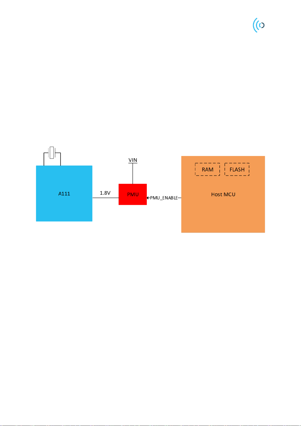
2.1 Power....................................................................................................................................... 6
2.2 SPI Interface............................................................................................................................ 7
3 HW Integration - PCB..................................................................................................................... 8
3.1 Sensor ground plane................................................................................................................ 8
3.2 Sensor underfill ....................................................................................................................... 9
3.3 Integration with other components.......................................................................................... 9
3.4 A111 Decoupling capacitors ................................................................................................. 10
3.5 A111 Crystal.......................................................................................................................... 11
4 Physical Integration....................................................................................................................... 13
4.1 Radome integration ............................................................................................................... 13
4.2 Radome thickness.................................................................................................................. 15
4.3 Radome distance.................................................................................................................... 16
4.4 Impact on the radiation pattern.............................................................................................. 18
4.5 Multi-layer radome integration.............................................................................................. 20
5 Physical Integration - Lens............................................................................................................ 22
5.1 Focal distance........................................................................................................................ 23
5.2 Radiation pattern................................................................................................................... 25
5.3 FZP Lens Design................................................................................................................... 26
6 Appendix A: Materials.................................................................................................................. 29
7 References..................................................................................................................................... 30
8 Revision......................................................................................................................................... 31
Disclaimer ............................................................................................................................................. 32

Hardware and physical integration guideline PCR Sensor A111
Page 4 of 32
深圳市佰誉达科技有限公司 Tel: 0755-2328 2845 2019-12-04
1 Introduction
This document aims to provide general guidelines for the hardware and physical integration of the
Acconeer A111 radar sensor. The A111 sensor is a fully integrated 60 GHz radar including the
transmitter and receiver antenna. The Tx/Rx antenna is a folded-dipole type and the E-plane and H-
plane of the antennas are indicated in Figure 1. The radiation pattern of the radar transceiver can be
found in the A111 datasheet [1]
The provided guidelines aim to optimize the radar sensor performance when integrating it into your host
product.
Figure 1 Sensor mounted on a printed circuit board (PCB). E-plane and H-plane are highlighted with blue and red
color, respectively.
1.1 Radar loop equation
Consider a signal transmitted through free space to a radar target located at distance Rfrom the radar.
Assume there are no obstructions between the radar and the radar target, and the signal propagates along
a straight line between the two. The channel model associated with this transmission is called a line-of-
sight (LOS) channel. For the LOS channel, the corresponding received reflected power from a radar
target, i.e. the signal to noise ratio (SNR), can be defined as
Ris the distance of the radar to the target, is the radar loop gain,,including both the transmitter and
receiver chain (two-ways signal path), is the Radar Cross Section (RCS) of the scattering object and
determines the reflected power of the object’s material. RCS depends on the roughness, size and shape
of the scattering object. Moreover, SNR depends on the sensor profile setting. A comprehensive
explanation of the sensor profiles can be found in Acconeer’s “Radar Sensor Introduction” [2].

Hardware and physical integration guideline PCR Sensor A111
Page 5 of 32
2019-12-04 Tel: 0755-2328 2845 深圳市佰誉达科技有限公司
1.2 Radar radiation pattern
When characterizing the gain, we refer to the radar loop gain defined in the radar equation section.
Figure 2 shows the radar setup configuration for the radar radiation pattern measurement. The reflector
which in this case is circular trihedral corner (radius of 5 cm) is located at the far-field distance from the
sensor (1 m). The far-field distance can be determined by the aperture of the sensor and the radar target.
where A is the largest dimension of either the sensor or the radar target. Envelope service can be used
to collect the reflected power at the fix distance from the radar target at different rotation angle.
Figure 2 Measurement setup for sensor radiation pattern.

Hardware and physical integration guideline PCR Sensor A111
Page 6 of 32
深圳市佰誉达科技有限公司 Tel: 0755-2328 2845 2019-12-04
2 HW Integration - Schematics
2.1 Power
The A111 is powered by 1.8V and all the control signals and the SPI interface are 1.8V pins. It must
therefore be ensured that all host MCU pins connected to the A111 are at 1.8V. If this is not the case,
level-shifters must be used in between the A111 and the host MCU.
As mentioned in the power consumption summary of the A111 datasheet, the A111 consumes
typically 66uA when the ENABLE pin is set low. If the leakage current is to be even further reduced,
the power to the A111 must be switched off. It can be achieved either by using a low-leakage power
regulator with an enable/disable function (if 1.8V is not available in the system) or a low-leakage
power switch in between the two 1.8V domains. In both cases, a control signal, PMU_ENABLE, is
needed. See Figure 3 for details.
Figure 3 Block diagram of how to connect a Power Management Unit for controlling the 1.8V to the A111.
If the power to the A111 is switched off in between sweeps it is important that the control signals and
SPI interface are pulled low during this time, otherwise reverse leakage will occur via the ESD diodes
in the A111. If it is not possible to set the SPI interface in such a state (either via SW or by configuring
any level-shifters that might be used in the design), the problem can be solved by adding a power
switch only to VIO1 and VIO2. This way the leakage will be significantly lower than 66uA, but the
control signals and SPI interface of A111 will still be supplied by 1.8V and thus no reverse leakage
will occur. See Figure 4 for details. The Acconeer High Performance Module shows how to integrate a
power switch into the design, refer to the XM112 datasheet [3].

Hardware and physical integration guideline PCR Sensor A111
Page 7 of 32
2019-12-04 Tel: 0755-2328 2845 深圳市佰誉达科技有限公司
Figure 4 An example of how to connect a power switch to reduce the leakage current when A111 is powered off.
2.2 SPI Interface
To optimize the performance and speed of the SPI interface, the A111 and the MCU should be placed
on the same PCB. If it is necessary to route the SPI interface via a cable, it is recommended that
differential routing is done for SPI_CLK, SPI_MOSI and SPI_MISO. This is enabled by using a
differential driver circuit as described in the XC122/XR122 EVK HW User Guide [4]. An example is
shown in Figure 5.
Figure 5 An example of how to use differential driver circuit if the SPI interface between A111 and Host MCU is
routed via cable.

Hardware and physical integration guideline PCR Sensor A111
Page 8 of 32
深圳市佰誉达科技有限公司 Tel: 0755-2328 2845 2019-12-04
3 HW Integration - PCB
This chapter describes means of optimizing the sensor performance by properly designing the printed
circuit board (PCB).
3.1 Sensor ground plane
To optimize the sensor transceiver gain, the sensor must be shielded by a solid ground plane. The area
of the ground plane relates to the sensor transceiver gain as shown in Figure 6. It is recommended to
place the sensor at the center of the PCB to avoid any tilt on the main radiation beam of the antennas.
Figure 6 Simulated relative transceiver gain loss as a function of extended board ground plane area. The area is
quadratic.
In terms of regulatory compliance, any holes in the ground shield must be significantly smaller than the
wavelength of the radiation that is being blocked (5 mmfor the A111sensor), to effectively approximate
an unbroken conducting surface.
For manufacturing reasons, it is recommended to not flood the ground area in between the A111 ground
balls. It is recommended to connect the ground balls of A111 with individual traces. It is very important
to connect the ground below A111 to the Main ground plane surrounding the A111. An example of how
to properly connect the sensor ground plane is shown in Figure 7.

Hardware and physical integration guideline PCR Sensor A111
Page 9 of 32
2019-12-04 Tel: 0755-2328 2845 深圳市佰誉达科技有限公司
Figure 7 An example of a properly connected ground plane below the A111 radar sensor.
3.2 Sensor underfill
Underfills are usually made of materials which are characterized by their dielectric properties. The
sensor underfill material should be chosen to have as low dielectric constant and loss tangent as possible.
Dielectric constant determines the reflectivity of the medium and loss tangent indicates the dissipation
effect of the material and both are frequency dependent.
3.3 Integration with other components
It is optimal to have no electronic components on the same side of the PCB as the sensor is located. The
electronic components located on the same side of the PCB as the sensor will cause the EM waves to be
scattered. The component size, shape and material determine the amount of scattered energy from the
component. If it is necessary to locate a component on the same side as the sensor, the distance between
the sensor and the component must be taken into consideration.
Figure 8 illustrates different strategies for placing a component close to the sensor. This is important to
consider when detection range is set to close-range (distances < 150 mm), as reflections from the
components can cause coherent or non-coherent interference. It is recommended to place the object in
the green areas as highlighted in Figure 8. The highlighted yellow area is more sensitive tothe placement

Hardware and physical integration guideline PCR Sensor A111
Page 10 of 32
深圳市佰誉达科技有限公司 Tel: 0755-2328 2845 2019-12-04
of an object. Optimum distance depends on the material, shape, size and orientation of the object.
Moreover, the height of the object should not exceed the sensor’s height.
Figure 8 Guideline for placement ofa component on the side of the sensor.
In case of having multiple components and objects nearby and if the radar performance is impacted by
the objects in proximity, it is recommended to shield the sensor by creating a conductive tapered wall
around the sensor. Figure 9 shows a model of such a shield can. The inner-walls of the can are tapered
and conductive coated, in order to minimize the unwanted reflections.
Figure 9 Tapered shield wall designed to prevent unwanted reflections from components placed close to the radar
sensor.
3.4 A111 Decoupling capacitors
Ideally, the decoupling capacitors should be placed on the opposite side of the PCB from the sensor,
but as close as possible to the via connecting the top and bottom layer. If manufacturing process
allows, the via can be placed directly on the A111 VIO ball. If that is not possible, the impedance
between the A111 VIO ball and the decoupling capacitor should be minimized. In practice, that means
that the via should be placed as close as possible to the VIO balls on A111 and the trace between the
A111 balls and the via, as well as the trace between the via and the decoupling capacitor, should be as
short as possible. In Figure 10 an example of how to place the via and decoupling capacitor is shown.
A four-layer PCB is shown in the example and the components and traces are highlighted in red.

Hardware and physical integration guideline PCR Sensor A111
Page 11 of 32
2019-12-04 Tel: 0755-2328 2845 深圳市佰誉达科技有限公司
Figure 10 An example how to place the Layer 1:4 via and decoupling capacitor C (Layer 4) that decouples ball D10 on
A111 (Layer 1). All components with orange component outlines are placed on Layer 4 while the A111 is placed on
Layer 1.
3.5 A111 Crystal
Ideally, the crystal and its tuning capacitors should be placed on the opposite side of the PCB from the
sensor, but as close as possible to the via connecting the top and bottom layer. If manufacturing
process allows, the via can be placed directly on the A111 XIN/XOUT balls. If that is not possible, the
impedance between the A111 XIN/XOUT balls and the crystal should be minimized. In practice, that
means that the via should be placed as close as possible to the XIN/XOUT balls on A111 and the trace
between the A111 balls and the via, as well as the trace between the via, the tuning capacitor and the
crystal pads, should be as short as possible. In Figure 11 an example of how to place the crystal, tuning
capacitors and vias is shown. A four-layer PCB is shown in the example and the components and
traces are highlighted in red.

Hardware and physical integration guideline PCR Sensor A111
Page 12 of 32
深圳市佰誉达科技有限公司 Tel: 0755-2328 2845 2019-12-04
Figure 11 An example how to place the A111 crystal (Layer 4), its tuning capacitors (C1, C2, Layer 4) and vias (Layer
1:4). The crystal is connected to balls J10 and H10 on A111 (Layer 1). All components with light blue component
outline are placed on Layer 4 while the A111 is placed on Layer 1.

Hardware and physical integration guideline PCR Sensor A111
Page 13 of 32
2019-12-04 Tel: 0755-2328 2845 深圳市佰誉达科技有限公司
4 Physical Integration
EM waves can interact with the objects and the media in which they travel. As EM waves propagate,
they can be reflected, refracted, or diffracted. These interactions cause the radar pulse to change the
direction and to reach the areas which would not be possible if the radar pulse travelled in a direct line.
This chapter provides the integration guidelines for simplified sensor cover scenarios. In any case, it is
important to carefully design and characterize the integration to ensure that the desired performance is
obtained. The radiation pattern presented in the A111 datasheet (www.developer.acconeer.com), shows
the sensor performance when integrated in free space.
4.1 Radome integration
A radome is a structural enclosure that protects a radar assembly. Radomes are generally made of
materials which are mainly characterized by their dielectric properties. Dielectric materials have a
characteristic impedance of
where is the dielectric constant relative to the free space and is the wave impedance in free-space.
= 377
When an EM wave hits a dielectric material at a normal incident angle, the reflection coefficient is
defined as
=
The transmission coefficient is defined as T = 1 +. It is important to select dielectric materials for the
radome such that the reflection coefficient has a low value. Therefore, a low dielectric constant material
will minimize the reflections and reduce the impact on the radiation pattern and insertion loss. Typically,
radomes are made of plastic and the dielectric constant of common plastic (ABS, PC, Teflon, PP) is less
than 3, therefore, reflection coefficient for plastic materials is usually low. To further optimize the
radome integration, shape of the radome, distance to the radar and the thickness of the radome needs to
be considered in the design.
Figure 12 shows a scenario where a 1mm thick radome made of ABS plastic is placed at different
distances, D, from the radar. The amplitude variation of the reflected waves from the radar target can be
seen in the measured results shown in Figure 13. The variation of the amplitude is explained by the
standing wave phenomena. The transmitted wave (indicated as blue in Figure 14) travels in the air
medium until it reaches the second medium (plastic cover). Depending on the properties of the second
medium, part of the energy will be transmitted through the medium and part of it will be reflected. The
reflected pulse (indicated as yellow in Figure 14) will travel back to the PCB and be reflected again
(indicated as red in Figure 14). Depending on the distance D, the transmitted wave and the reflected
pulse can add up coherently or noncoherently. The maximum and minimum occur at multiples of the
half wavelength of the radar pulse. The impact of the pulse length is visible in the measurement results
(Figure 13). When the distance D gets larger than the pulse length, the standing wave disappears.

Hardware and physical integration guideline PCR Sensor A111
Page 14 of 32
深圳市佰誉达科技有限公司 Tel: 0755-2328 2845 2019-12-04
Figure 12 Placement of the radome in relation to the sensor.
Figure 13 Measured reflected power from the target versus the radome to sensor distance for two different service
profiles (ACC_SERVICE_ENVELOPE_PROFILE_MAXIMIZE_SNR and
ACC_SERVICE_ENVELOPE_PROFILE_MAXIMIZE_DEPTH_RESOLUTION). Amplitude is nomalized by the
maximum value of Free Space.
Figure 14 Illustration of the transmitted pulse and the reflected pulses (from plastic cover and the PCB).

Hardware and physical integration guideline PCR Sensor A111
Page 15 of 32
2019-12-04 Tel: 0755-2328 2845 深圳市佰誉达科技有限公司
4.2 Radome thickness
When an EM wave travels in a dielectric material, its effective propagation speed and the wavelength
will change depending on the dielectric material:
,
where is the dielectric constant of the material, is the speed of light in free space, i.e. 3×10⁸
andis the free space wavelength (for A111).
Reflections happens at the air-dielectric interfaces and the thickness of the dielectric medium determines
the phase shift of the reflected wave from dielectric-air interface. Figure 15 shows a simplified model
of the transmission and reflections of the waves between air-dielectric. Reflections from the second
bounce and above are neglected in this model. When the wave impinges the air-dielectric interface, part
of it reflects () and part of it transmits (). The thickness of the dielectric material will cause the
wave to shift phase by:
where is the thickness of the dielectric. When the wave reaches the dielectric-air interface (),
another transmission () and reflections () happens. Notice that the wave will have
a sign change when the reflection happens, . At the lower dielectric-air interface, the
amplitude of the wave is , where the wave has traveled a distance of .
If we assume a half-wavelength-thick radome, the round trip of the wave inside the radome will
introduce a 360-degree phase shift. Hence, the reflected wave into the air has a amplitude.
In this case, the reflected waves will cancel out. Therefore, to minimize the
reflections, the thickness of a single layer radome should be half-a-wavelength or a multiple of it.
Figure 15 Incident wave impinging the radome at the normal incident angle. Transmission and reflection of the wave
at the interfaces of two mediums.
As an example, a plastic sheet made of ABS with different thicknesses was selected for the test
measurement. If we assume dielectric constant of ABS to be 2.6 (the dielectric constant can vary
depending on the vendor), the thickness of the half-a-wavelength-thick radome is calculated to be

Hardware and physical integration guideline PCR Sensor A111
Page 16 of 32
深圳市佰誉达科技有限公司 Tel: 0755-2328 2845 2019-12-04
Figure 16 shows the amplitude variation of the reflected wave from the radar target when the distance
between the sensor and the radome is varied for different radome thicknesses. A thickness of 1.6 mm,
which is very close to the thickness of half-a-wavelength, has the minimum impact on the amplitude
variation. It is worth to mention that when the thickness is set to quarter-of-a-wavelength, the amplitude
variation becomes maximum. When the radome thickness is set to quarter-of-a-wavelength, the round
trip of the wave inside the radome leads to a 180° phaseshift.
Figure 16 Impact of the thickness of the radome (made of ABS) on the reflected amplitude variation. The amplitude is
normalized to maximum value of the Free Space (FS). Profile set to
ACC_SERVICE_ENVELOPE_PROFILE_MAXIMIZE_SNR.
If absolute measurements are required for a certain use case, it is advised that an additional offset is
added to the distance measurement. The reason for this offset is that the propagation delay caused by
the radome must be compensated. This additional offset is obtained by making reference measurements,
and it will also allow you to place the reference plane at the desired location for your product.
4.3 Radome distance
The reflected waves from the radome wall should be in-phase with the transmit waves, which leads to
the optimum distance of

Hardware and physical integration guideline PCR Sensor A111
Page 17 of 32
2019-12-04 Tel: 0755-2328 2845 深圳市佰誉达科技有限公司
The optimum distance is valid if the thickness of the radome is optimum as well. Otherwise, to have a
minimum insertion loss on the received signal, the distance to the sensor should follow the marginal
criteria below:
In order to have zero insertion loss is determined to be 0.5 mm.

Hardware and physical integration guideline PCR Sensor A111
Page 18 of 32
深圳市佰誉达科技有限公司 Tel: 0755-2328 2845 2019-12-04
4.4 Impact on the radiation pattern
The radiation pattern of the integrated antennas will be affected by the dome that is put on top of the
sensor. Figure 17 shows the measured radar loop pattern for three different materials, ABS plastic,
gorilla glass and free space.
Figure 17 Impact of the different materials on the radiation pattern, H-plane.
Figure 18 shows the radar radiation pattern when a radome made of ABS with 2mm thickness is placed
at distances corresponding to the harmonics of the quarter-of-a-wavelength of the radar pulse. The
reference case is FS (Free Space i.e. no cover). Since the radome thickness is not optimal, distances
which correspond to odd harmonics of the quarter-of-a-wavelength have the minimum impact on the
radiation pattern.

Hardware and physical integration guideline PCR Sensor A111
Page 19 of 32
2019-12-04 Tel: 0755-2328 2845 深圳市佰誉达科技有限公司
Figure 18 Impact of the radome-to-sensor distance on the radiation pattern (H-plane).
It is not recommended to place the cover directly on the sensor. Figure 19 shows the radiation pattern
on the H-plane when the cover (ABS plastic sheet) is located on top of the sensor. In comparison with
Free Space, there is around 3 dB loss on both max. power and total radiated power for this case.
Figure 19 Radiation pattern on H-plane, cover placed directly on the sensor vs Free Space.

Hardware and physical integration guideline PCR Sensor A111
Page 20 of 32
深圳市佰誉达科技有限公司 Tel: 0755-2328 2845 2019-12-04
4.5 Multi-layer radome integration
Radomes can also be constructed from a multi-layer dielectric. Particularly, where the thickness of a
single layer dielectric is fixed, thus additional layer can be added to the radome which can act as an
anti-reflection layer. Figure 20 shows the stack-up of a radome made of two dielectric layers and
illustrates the scattering of waves in this scenario. In this scenario, the reflections formed at the
interfaces of the different mediums can be cancelled if the condition below is satisfied:
The layer indicated with dielectric constant is the main layer and the layer with the dielectric
constant is the matching layer. Depending on the degree of the freedom, one can find the optimum
thickness or the optimum dielectric constant for the anti-reflection layer.
Figure 20 Illustration of the scattering waves for a two-layer radome.
Another approach is to use an EM simulation tool to find the characteristic of the anti-reflection layer.
For example, Figure 21 shows a sensor integration scenario where the main layer of the radome is made
of a special glass which has a high dielectric constant (~6-7). Therefore, the wave impedance mismatch
between the glass and the air becomes large. To reduce the mismatch, a matching layer with a lower
dielectric is applied between sensor and the screen. To find the optimum dielectric value of the matching
layer, the dielectric constant is varied in the simulation. It can be seen from the results shown in Figure
22 that the gain drops at least 2 dB in case 1, compared to case 2 where the matching layer has a dielectric
constant of 3.
Other manuals for A111
2
Table of contents
Other Acconeer Accessories manuals
Popular Accessories manuals by other brands

MasterChef
MasterChef 043-5784-2 instruction manual

Puretec
Puretec Radfire RI-NSFA Series user manual

IR-Tec
IR-Tec wallSenzr LDT-700 Series installation instructions

Comfort audio
Comfort audio Programmer DT20 Instructions for use

Entrematic
Entrematic LIN2 installation manual

Chef's Choice
Chef's Choice Angle Select 1520 instructions

Silvercrest
Silvercrest SPB 10000 A1 operating instructions

Flo-tech
Flo-tech FT300 instruction manual

AutomationDirect
AutomationDirect AcuAMP ACS035 Series installation instructions

globalwater
globalwater WQ730 manual

Green Brook
Green Brook DW040A manual

Data Video
Data Video Holder RKM-572 instruction manual