manuals.online logo
Brands
  1. Home
  2. •
  3. Brands
  4. •
  5. Accuphase
  6. •
  7. Recording Equipment
  8. •
  9. Accuphase AD-50 User manual

Accuphase AD-50 User manual

使用方法
取り付け方法
このたびは、アナログ・ディスク入力ボードAD-50をお買い上げいただきまして誠にありがとう
ござ い ま す 。こ の オプ ション・ボ ード は 、リア パ ネ ル の オ プ ション 用 スロットに 増 設して 、ア ナ ログ・
プレーヤーの再生にご使用ください。
使用方法は、ボードを増設する機器により異なりますので、使用前に必ず各機器の取扱説明書を
参照してください。
取扱説明書
820-3317-00 (B1) Printed in JapanJ171.3X
アナログ・ディスク入力ボード AD-50
アキュフェーズ株式会社
〒225-8508 横浜市青葉区新石川2-14-10
 TEL045(901)2771(代)
❶増設する機器の電源を切ります。
❷リアパネルのオプション用スロットのサブパネルを外しま
す 。( 図1 参照)
 ※外したサブパネルは保管しておいてください。
❸オプション用スロットの上下のガイドレールに沿って、オプ
ション・ボ ードを 挿 入( 図2 参照)します。コネクターに当って
止まったら、少し力を入れてパネル面が同一になるまで差
し込みます。
❹上下のネジ2カ所で確実に固定します。
●オプション・ボードを抜き差しするときは、必ず増設する機器の電源を切る。
 電源を入れたまま抜き差しすると、故障の原因となります。
●サブパネルを外したとき、スロット内部に手などを入れない。(スロット内部に、オプション・ボード以外は入れないで
く だ さ い 。)
●部品やハンダ、コネクターの接点部分を手で触らない。手で触れると接触不良や回路が故障する原因となることがあ
ります。ボードを持つ場合にはプリント板の外周やパネル部を持ってください。
●オプション・ボードの取り付けネジは手で完全に締める。締めつけが不完全ですと、端子がグラウンドから浮いて接
触不良となり、故障の原因となることがあります。
●入力端子やコネクターなどに接点復活剤や導電剤などは絶対使用しない。これらの要因による不具合は保証対象外
となります。
注意
LEFT, RIGHT-アナログ・プレーヤー入力端子
   アナログ・プレーヤーの出力ケーブルを接続します。
GND-アース端子
   アナログ・プレーヤーの出力ケーブルと一緒に出ているアース線を接続します。
❶S1 : MC/MM
─
イコライザーゲインの切替
一般的には、MCカートリッジの内部インピーダンスが
 20Ω以上:100Ωまたは300Ωに設定
 20Ω以下:30Ωまたは100Ωに設定
●
カートリッジの内部インピーダンスの2~3倍以上を
目安にしますが、実際に試聴して良い音質の得られ
るインピーダンスを決定してください。
このフィルタ-は、超低域25Hz以下を-12dB/
octaveの減衰特性でカットし、超低域ノイズが
可聴帯域内へ悪影響をおよぼすことを防ぎま
す。レコードに大きな反りがあったり、超低域の
振動によりウーファーがゆれたりするときに大
変有効です。
MM:高出力電圧のMM型カートリッジのポジションです。
 ゲイン :40dB
 入力インピーダンス:47kΩ
MC:出力電圧が低いMC型のカートリッジのポジションです。
 ゲイン :66dB
 入力インピーダンス:S3で切替え
S1, S2, S3 : ディップスイッチの設定…挿入前に設定します。
注意:スイッチの各キーは、先の細いもので完全にセットしてください。指定以外の設定では所定の特性を得られません。
❶ S1 : MC/MM
イコライザーゲインの切替
❷ S2 : SUBSONIC FILTER
サブソニック・フィルターのON/OFF
❸ S3 : MC IMPEDANCE
MCの入力インピーダンスの選択 :
30/100/300Ω
増設する機器のパネル面に、「MC/MM切替機
能」がある場合、パネル面の切り替えが優先され
るため、ボード上のS1の設定は必要ありません。
S1
AD-50
部品面(S1~S3のスイッチ位置を示す。)
S3
S2
SUBSONIC
FILTER MC
IMPEDANCE
MC/MM
❷S2 : SUBSONIC FILTER ─ サブソニック・フィルターのON/OFF
❸S3 : MC IMPEDANCE ─ MCの入力インピーダンスの選択
1, 2, 3, 4 : OFF
3, 4 : ON
1, 2 : OFF
1, 2 : ON
3, 4 : OFF
300Ω
30Ω
100Ω
出荷位置
1 2 3 4
ON
1 2 3 4
ON
1 2 3 4
ON
スイッチを正面から見た図を示しています。
1, 2 : OFF
1, 2 : ON
MM
MC
出荷位置
1
ON
2
1
ON
2
スイッチを正面から見た図を示しています。
ON OFF
キーを止まるまで押し
下げる
キーを止まるまで
上げて水平にする
スイッチは横から見た図を示しています。
お願い 製品に対するお問い合わせ、または異常が認められる
ときは、お求めの当社製品取扱店、または当社品質
保証部へご連絡ください。
 お客様カードは付属していません。
1, 2, 3, 4, 5, 6 : OFF
1, 2, 3, 4, 5, 6 : ON
OFF
ON
出荷位置
1 2 3 4
ON
1 2 3
56
56
4
ON
スイッチを正面から見た図を示しています。
*イラストは E-650 です。
サブパネル
オプシ ョ ン ・ ボード
図1 図2
ガ イド レ ー ル
ガ イド レ ー ル
Using the AD-50
How to install
Thank you for your purchase of the AD-50 Analog Disc Input Board. This optional board
mounts into the rear panel of your supporting Accuphase device, allowing the unit to connect
to and play from analog disc players.
Operation of this board varies according to the Accuphase device in which it is mounted.
Please refer to the documentation for your Accuphase device before using this board.
INSTRUCTION MANUAL
820-3317-00 (B1) Printed in JapanJ171.3X
Analog Disc Input Board AD-50
LEFT and RIGHT analog player input jacks
Connects to the output cables from the analog record player.
GND terminal
Connects to the ground cable from the analog record player.
In general, you should set this according to the MC
cartridge’s rated internal impedance, as follows.
20 ohms or higher: Set to 100 or 300 ohms.
Below 20 ohms: Set to 30 or 100 ohms.
●As a guideline, the impedance setting should be about
2 to 3 times the cartridge’s internal impedance. But you
should test the setting by ear, and feel free to change it
to get the best sound.
This is a low-cut filter with a cutoff frequency of
25 Hz and a steep attenuation curve (-12 dB/octave).
Its purpose is to filter out very low frequency noise
that might otherwise adversely affect audible ranges.
It is very effective for removing rumble noise from
warped records and for preventing woofers from
bottoming out.
Before installing the board, set board DIP switches S1to S3 as explained below.
❶ S1 : MC/MM
Equalizer gain swit
❷ S2 : SUBSONIC FILTER
Subsonic lter ON/OFF
❸ S3 : MC IMPEDANCE
Selects MC input impedance:
30, 100, or 300 ohms.
S1
S3
S2
SUBSONIC
FILTER MC
IMPEDANCE
MC/MM
AD-50 Component Side (DIP-switch locations)
❷S2: SUBSONIC FILTER - Subsonic lter ON/OFF
❸S3: MC IMPEDANCE -Selects the MC input impedance.
Illustration shows installation on the E-650.
Note: Use a pointed object to set the DIP-switch bits, and be sure that all bits are set correctly. The board may
not function properly if any of the bits are out of position.
ON OFF
Push key down until it
stops.
Push key up until it
stops.
(Illustration shows side view of switch.)
SI settings are meaningless if you are mounting
the board into a unit that includes an MC/MM
switch on its panel, as the panel setting takes
precedence.
MM: Moving-magnet cartridge (high output voltage)
Gain: 40 dB
Input Impedance : 47 kilohms
MC: Moving-coil cartridge (low output voltage)
Gain : 66 dB
Input Impedance : As set by S3.
❶S1: MC/MM -Equalizer gain switch
1, 2 : OFF
1, 2 : ON
MM
MC
Factory setting
1
ON
2
1
ON
2
Illustrations show front view of switch.
1, 2, 3, 4, 5, 6 : OFF
1, 2, 3, 4, 5, 6 : ON
OFF
ON
Factory setting
1 2 3 4
ON
1 2 3
56
56
4
ON
Illustrations show front view of switch.
1, 2, 3, 4 : OFF
3, 4 : ON
1, 2 : OFF
1, 2 : ON
3, 4 : OFF
30
0Ω
30Ω
10
0Ω
1 2 3 4
ON
1 2 3 4
ON
1 2 3 4
ON
Factory setting
Illustrations show front view of switch.
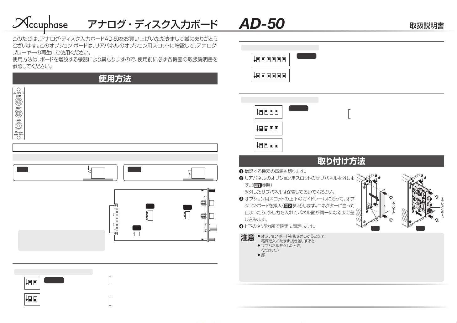
❶Turn off the device power.
❷On the rear panel, remove the sub panel of the slot you
wish to use. (See Fig. 1. )
◆Retain the sub panel for future use.
❸
Insert the option board into the slot, along the slot’s
upper and lower guide rails (see Fig. 2. ). When the rear
of the board reaches the internal connectors, give a
gentle push to snap the connection into place, so that
the front of the board becomes ush with the panel.
❹
Secure the board by screwing in the top and bottom
screws.
● Turn off the device power before installing or removing option boards. Installing a board
while power is on may damage the equipment.
● Keep ngers out of the opened slot. Do not place anything other than the board into the slot.
● Avoid touching the board’s soldered areas, connector contacts, and components. Touching
these areas may damage the circuitry or the contact. Hold the board by the edges or along
its panel.
● Tightly screw in the two screws all the way (by hand). If screws are loose, terminals may
separate from ground, resulting in poor contact or equipment damage.
● Do not use electrical contact enhancers or conductivity agents on input jacks and
connectors, as these may cause aging in resin parts and lead to damage.
Caution
Guide rail
Guide rail
Fig. 1. Fig. 2.
Subpanel Option
board
ACCUPHASE LABORATORY, INC.
YOKOHAMA, JAPAN

Other Accuphase Recording Equipment manuals

Accuphase AD-2900 User manual

Accuphase

Accuphase AD-2900 User manual

Accuphase AD-30 User manual

Accuphase

Accuphase AD-30 User manual

Popular Recording Equipment manuals by other brands

Focusrite vocaster two user manual

Focusrite

Focusrite vocaster two user manual

Anatek Pocket Record operating instructions

Anatek

Anatek Pocket Record operating instructions

Roland RV-330 Algorithm guide

Roland

Roland RV-330 Algorithm guide

Xilica Audio Design XM-2040 user manual

Xilica Audio Design

Xilica Audio Design XM-2040 user manual

PXM PX313 manual

PXM

PXM PX313 manual

Kurzweil KME61 - REV A user guide

Kurzweil

Kurzweil KME61 - REV A user guide

Ambient Recording ACN-TL TinyLockit manual

Ambient Recording

Ambient Recording ACN-TL TinyLockit manual

Olympia MEMO88 operating instructions

Olympia

Olympia MEMO88 operating instructions

Agilent Technologies E5805A installation guide

Agilent Technologies

Agilent Technologies E5805A installation guide

Roland MT-100 owner's manual

Roland

Roland MT-100 owner's manual

Peak PCAN-ISA user manual

Peak

Peak PCAN-ISA user manual

Zoom R20 Firmware update guide

Zoom

Zoom R20 Firmware update guide

Akai EWV2000 Operator's manual

Akai

Akai EWV2000 Operator's manual

Lantronix NM2-GXE-2230 201 Series installation guide

Lantronix

Lantronix NM2-GXE-2230 201 Series installation guide

The t.racks TFX256 PRO user manual

The t.racks

The t.racks TFX256 PRO user manual

Avago MC68HC11 Application brief

Avago

Avago MC68HC11 Application brief

Evco EVIF21RS quick start guide

Evco

Evco EVIF21RS quick start guide

Rolls SS412 manual

Rolls

Rolls SS412 manual

manuals.online logo
manuals.online logoBrands
  • About & Mission
  • Contact us
  • Privacy Policy
  • Terms and Conditions

Copyright 2025 Manuals.Online. All Rights Reserved.