bmcm USB-OI16 User manual

USB-OI16
Isolated Digital I/O Interface (USB)
32 Channels. Monitor & Control.
Galvanically Isolated.
Record and output digital signals electrically
isolated. The USB-OI16 features two 16-bit ports
with 16 digital inputs and outputs each. Besides
that, up to 2 counters or incremental encoders can
be connected at the first digital inputs.
16 Optocoupler Inputs.
16 Semiconductor Switches.
16 digital states in the 3..32V voltage range can be
sampled and recorded. The 16 semiconductor
switches of the USB-OI16 are realized with high-
side drivers for voltages in the 5..32V range.
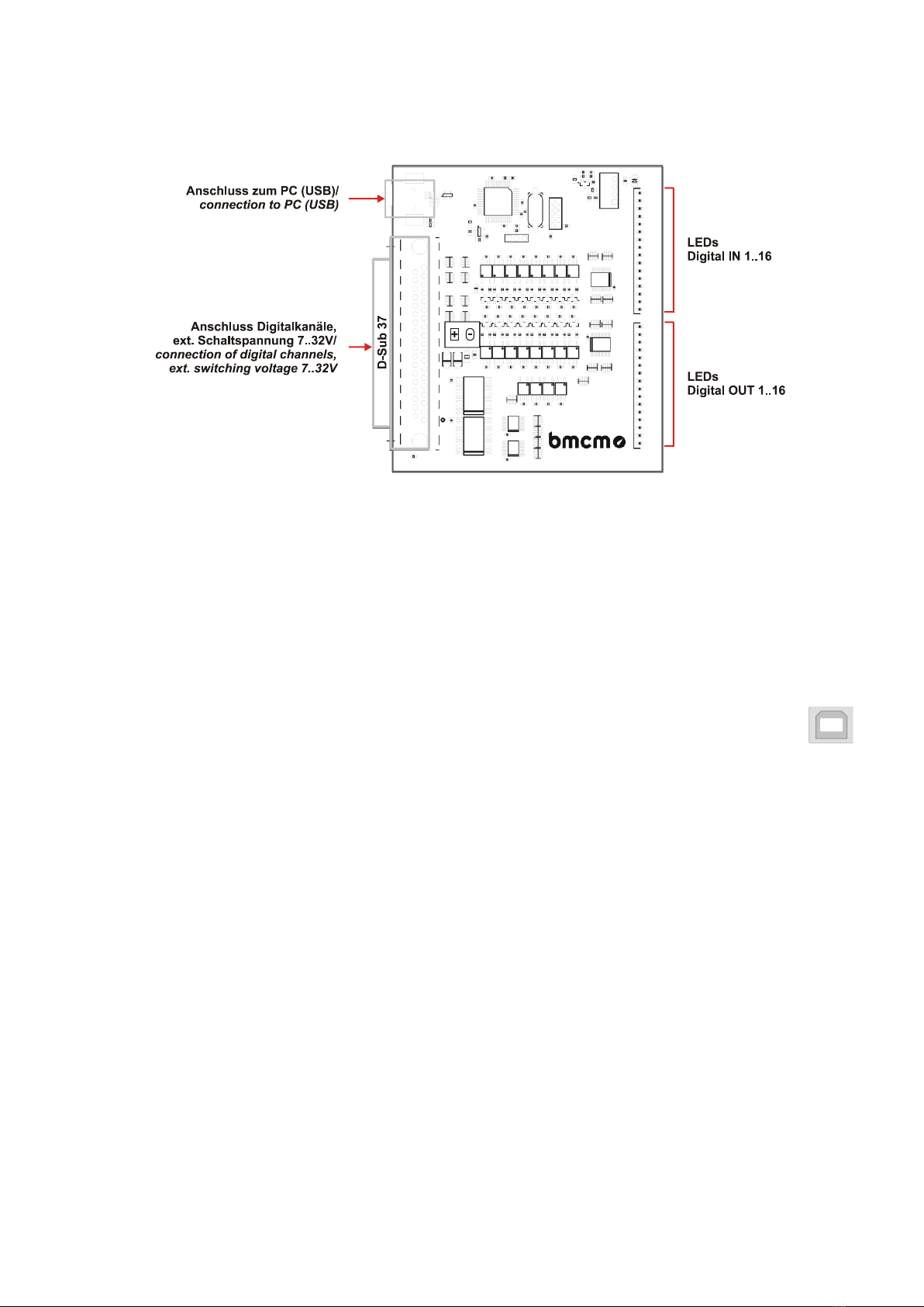
Enlightened.
The state of the input and output lines is indicated
by LEDs.
Count and Measure: Pulses.
Frequency. Position. Period.
If for the acquisition of large quantities, speed
measurement, or determination of position: These
are only a few applications the two 32-bit counters
(incremental decoders) of the USB-OI16 can be
used for. The integrated pulse time measurement
function produces precise results especially in the
low-frequency range.
Get Connected.
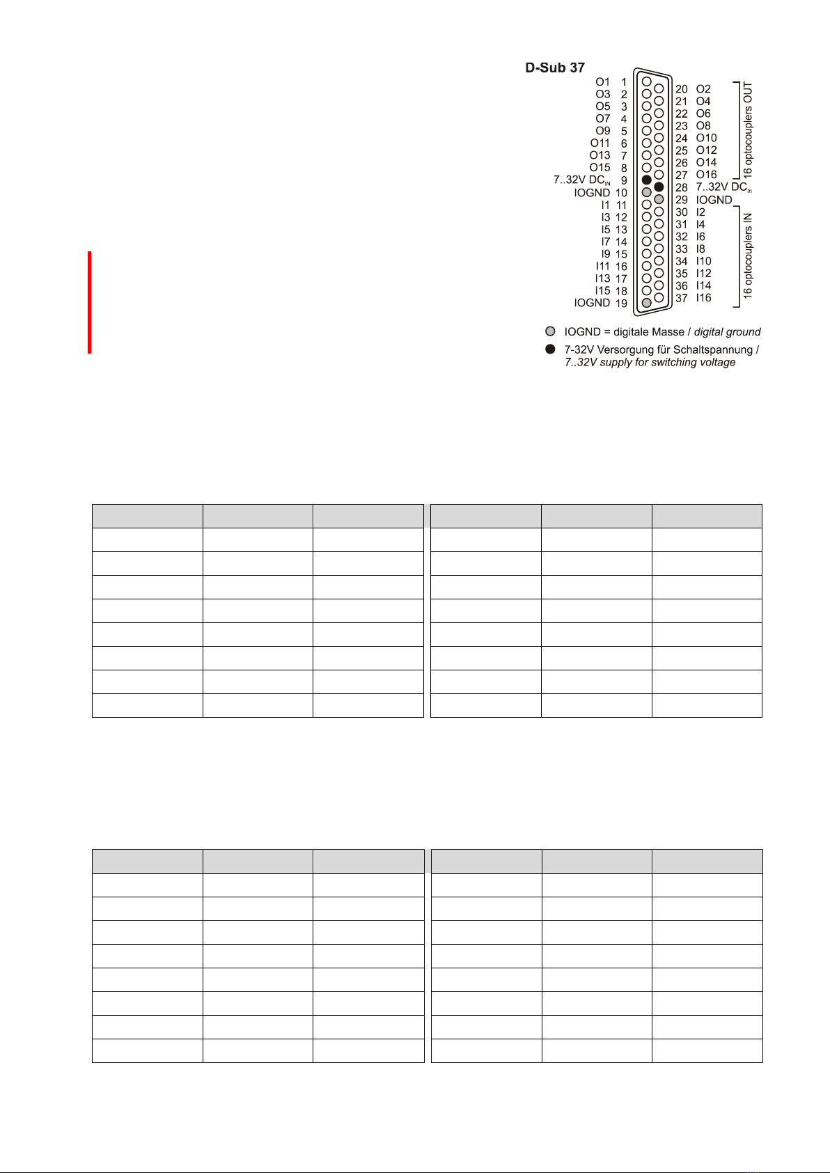
The digital channels of the application-specific
hardware (sensor, machine, etc.) are connected at
a 37-pin D-Sub female.
Plug & Play.
The connection to the PC is realized via USB. The
USB-OI16 provides all typical USB features (e.g.
Plug&Play, Hot-Plug). Up to 127 devices can be
connected and installed during operation.
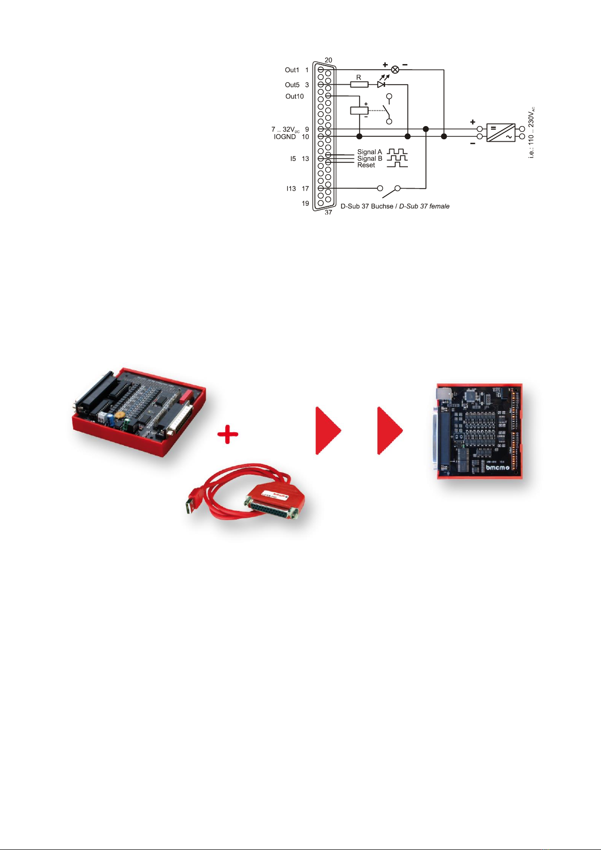
Self-Powered.
The device is internally supplied with 5V provided
by the USB interface. This reduces cabling efforts
to a minimum and makes mobile measurements a
lot easier. An external supply unit can be
connected for higher output switching voltages at
the digital outputs (7..32V).
Open for Everyone.
Widely supported: The USB-OI16 can be used
under Windows®XP/7/8/10 as well as under Mac
OS X, Free BSD, and Linux. The software for
installation and programming is included for free.
NextView®. Try for Free.
The device is supported by NextView®, the
software for data acquisition and analysis. A fully
functional 14-day trial is included with delivery to
directly test the functionality of the USB-OI16.
Functional diagram

USB-OI16
Seite 2
1Start-up procedure
All available software and documentation for the USB-OI16 are located on www.bmcm.de/usb-oi16-en
in the tab Downloads.
1. Step: Installation device driver
Install the latest driver package in order to use the USB measurement device. You will
find the package on www.bmcm.de/usb-oi16-en in the tab Downloads in the category
BMCM –Drivers. Open the manual device drivers on www.bmcm.de/man-driver for
more information.
2. Step: Connect up
Connect the provided USB cable to the device and to a free USB port of the PC.
Then start the plug and play installation. The device gets its power supply through the
USB connection. If the digital outputs require a switching voltage higher than the 5V
of the USB interface, an external power supply providing 7..32V can be connected.
3a. Step: Measuring with NextView
To be able to use your measurement system with NextView, you just need to
download and install the latest version of NextView on www.nextview.de/download. In
case you did not buy NextView, request a free of charge trial version when first
starting NextView. Find more information about NextView and its installation on
www.nextview.de or in the manual on www.bmcm.de/man-nextview.
3b. Step: Measuring with API
In case you want to use the measurement device without NextView, you need to download
and install the free of charge programming interface LIBAD4. You can find this on
www.bmcm.de/usb-oi16-en in the tab Downloads in the category LIBAD –Programming
Interface (API), too. Find more information on www.bmcm.de/libad-en or directly in the manual
www.bmcm.de/man-libad.

USB-OI16
Seite 3
2Block Diagram
µController
USB
OUT 1 .. 16
D+
D-
1
7..32V (ext.)
2
9
8
10
B
.
.
.
.
.
.
16
.
.
..
.
.
.
.
.
.
.
.
IN 1 .. 16
1
2
3
16
15
.
.
.
A
.
.
.
.
.
.
DC/DC
Treiber/
Driver
5V(i nt.)
Treiber/
Driver

USB-OI16
Seite 4
3Operating Elements, Connections, and Pin Assignments
The available connections and components of the USB-OI16 are shown in the following figure of the
board (view on top of the board (fitted with components), D-Sub 37 connector on the left).
Figure 1
3.1 LEDs
16 LEDs on the USB-OI16 (see Figure 1, p. 4), each dedicated to the inputs and outputs, are turned
on when a digital channel is high.
3.2 Connection to the PC
The standard USB connector (type B) serves for the connection of the USB-OI16 to the PC.
5V voltage supply is also provided via the USB interface.
3.3 Switching Voltage
A 7..32V DC switching voltage for the digital outputs can be connected at the 37-pin D-Sub female.
If there is no external power supply unit, a 5V power supply is generated internally for the outputs
1..16. The switching current per output in this case is 1mA.

USB-OI16
Seite 5
3.4 Digital Channels
The digital lines are attached to the 37-pin D-Sub female
(see Figure 1, p. 4). Electrical isolation to the PC is
guaranteed by optocouplers on the USB-OI16.
The digital lines are addressed via two 16-bit ports A and B
by software. The 16 digital inputs (port A: I1..I16) and the 16
digital outputs (port B: O1..O16) are hard-wired at the D-
Sub 37.
•Please carefully observe the polarity! Only apply voltages
within the adjusted range!
•IOGND must never be connected to PC-GND (USB), as
this would override the galvanic isolation!
3.4.1 Digital Inputs
Up to 16 digital inputs are provided for digital sensors or other digital signal sources in the 3..32V
range at the connections I1..I16.
The following table and figure shows the pin assignment of the digital inputs at the 37-pin D-Sub
female and the related port assignment:
Digital IN
D-Sub37
Port/Bit
Digital IN
D-Sub37
Port / Bit
I1
11
A/0
I9
15
A/8
I2
30
A/1
I10
34
A/9
I3
12
A/2
I11
16
A/10
I4
31
A/3
I12
35
A/11
I5
13
A/4
I13
17
A/12
I6
32
A/5
I14
36
A/13
I7
14
A/6
I15
18
A/14
I8
33
A/7
I16
37
A/15
3.4.2 Digital Outputs
To control machines, switch a relay, etc. with 5V or 7..32V (see chapter 3.3), the 16 digital outputs
O1..O16 can be used.
counter :
Digital OUT
D-Sub37
Port/Bit
Digital OUT
D-Sub37
Port/Bit
O1
1
B/0
O9
5
B/8
O2
20
B/1
O10
24
B/9
O3
2
B/2
O11
6
B/10
O4
21
B/3
O12
25
B/11
O5
3
B/4
O13
7
B/12
O6
22
B/5
O14
26
B/13
O7
4
B/6
O15
8
B/14
O8
23
B/7
O16
27
B/15

USB-OI16
Seite 6
3.5 Counters with Pulse Time Measurement
The USB-OI16 features two 32-bit counters allowing the
connection of incremental encoders.
The counter inputs (A, B, and Reset) are configured by
software and can be reached then at the first digital input
pins (counter 1: I1-I3; counter 2: I4-I6).
The following table and figure shows the pin assignment of
the counter inputs at the 37-pin D-Sub female:
The USB-OI16 counts the number of
incoming pulses (max. 250kHz)
sampled at the connection of signal
A. If the maximum counting range is
reached, the counter will be reset to
the minimum value of the counting
range.
If the external counter reset is
connected, the counter can be reset
at any time.
In comparison to a counter, the quadrature decoder considers the counting direction by decoding a
second phase-shifted signal.
To activate the counting function, the respective digital lines of the USB-OI16 must be assigned to the
counter via software.
Function
Description
Max. pulse frequ.
Connection
Pins/Counter
Counting range
Counter
count
250kHz
Signal A
1
0..232-1
Up/Down counter
count
100kHz
Signal A, Signal B
2
-231 .. 231-1
Incremental encoder
count
100kHz
Signal A, Signal B
2
-231 .. 231-1
Pulse time
measurement
measure time
betw. 2 edges,
resolution
41,67ns
250kHz
Signal A
1
0 - 178,96s
Please refer to the relevant documentation of your product for further information about connecting
your incremental encoder.
Counter 1
D-Sub37
Counter 2
D-Sub37
Signal A
11
Signal A
31
Signal B
30
Signal B
13
Reset
12
Reset
32

USB-OI16
Seite 7
3.6 Interfacing Example
The figure on the right shows the
connection of an incremental
encoder, a switch, a relay, an LED,
and a lamp to USB-OI16 with external
supply.
4Compatibility of the USB-OI16 to USB-PIO with OI16
The USB-OI16 incorporates all functions in one device provided by the combination of a USB-PIO and
OI16.
Therefore, the USB-OI16 can serve as an alternative for this hardware combination. All previously
used applications are fully compatible.

USB-OI16
Seite 8
5Important Notes for Using the USB-OI16
•The USB-OI16 is only suitable for extra-low voltages –please observe the relevant regulations!
•An electrically isolated power unit (with CE) must be used for power supply.
•All accessible pins are electrostatic sensitive devices. Provide for an earthed conductive work place when
installing.
•Only use non-solvent detergents for cleaning. The product is designed to be maintenance-free.
•The board must not be used for safety-relevant tasks. With the use of the product, the customer becomes
manufacturer by law and is therefore fully responsible for the proper installation and use of the product. In the
case of improper use and/or unauthorized interference, our warranty ceases and any warranty claim is
excluded.
Do not dispose of the product in the domestic waste or at any waste collection places. It has to be either duly
disposed according to the WEEE directive or can be returned to bmcm at your own expense.
6Technical Data
(typical at 20°C, after 5min., +5V supply)
•Digital Inputs
Number:
16 digital inputs, galvanically isolated by 16 optocouplers
Counters:
2 counters/incremental encoders (32 bit, opt. counter reset) can be connected at the first digital inputs
Counter frequency:
max. 250kHz
Input voltage:
3..32V DC (>2.5V = high)
Surge protection:
max. 60V DC for 10sec.
Input current // Input resistance:
max. 0.35mA // app. 100k
•Digital Outputs
Number:
16 digital outputs, galvanically isolated by 16 optocouplers with 2 high-side drivers
Switching voltage:
5V DC (internal supply) or 7..32V DC (external supply)
Voltage drop (with ext. supply):
app. 1.5V at the high-side driver
Switching current (with ext. supply):
max. 0.25A per output, max. 0.8A in total per 8-bit high-side driver at 25°C
•General
Power supply:
internal: 5V DC; external: 7..32V DC at 37-pin D-Sub female
Digital connection:
37-pin D-Sub female
USB interface:
attach to PC at USB connector (type B), USB 2.0
CE standards:
EN61000-6-1, EN61000-6-3, EN61010-1; for decl. of conformity (PDF) visit www.bmcm.de
ElektroG // ear registration:
RoHS and WEEE compliant // WEEE Reg.-No. DE75472248
Max. perm. potentials (galv. isolation):
60V DC acc. to VDE, max. 1kV ESD on open lines
Temperature ranges:
operating temp. -25..60 C, storage temp. -25..70 C
Relative humidity:
0..90% (not condensing)
Dimensions (L x W x H):
app. 97mm x 105mm x 30mm
Delivery:
device with DIN rail carrier and bracket, USB cable
Available accessories (optional):
connecting cables ZUKA37SB, ZUKA37SS, D-Sub plug ZU37ST,
gender changer ZU37SS, waterproof housings ZU-PBOX-PG
Warranty:
2 years from date of purchase at bmcm, claims for damages resulting from improper use excluded
•Software
Software free of charge download:
LIBAD4 SDK for C/C++ programming on Windows® XP/7/8/10, Mac OS X, Unix (FreeBSD, Linux); trial version
of the measuring software NextView®to test and operate the hardware
NextView®(optional):
professional software (versions: Professional, Lite) for the acquisition and analysis of measurement data on
Windows®8/10
Manufacturer: BMC Messsysteme GmbH. Subject to change due to technical improvements. Errors and printing errors excepted. Rev. 2.3 02/11/2020
Table of contents
Other bmcm Recording Equipment manuals