AccuTherm ACCSL2021 User manual

ACCSL2021
AccuTherm™ SmartLOG® 2021
FEATURES
• Monitor1or2WirelessTemperatureSensorsSimultaneously
• AmbientRoomTemperatureandHumidityDisplayed&Recorded
• SMSandEmailAlerts
• ReplaceableWirelessSensors!
Nodowntimeforsendingequipmentbackforcalibration.
Nofumblingwithwiresinfridge.
• BrightColorTouchDisplayforeaseofuse.
• WebDashboard,useanybrowseronlocalnetwork
Nocloud,Nosubscriptionfees!
• EnterpriseNetworkLoginforSecurity
• Timeautomaticallysynchronizedfrominternert
• Reportsin.PDFformat
• NoPCSoftwareneeded
*SecondTemperatureSensoroptional(cat#:ACCSLBLET)
NOTE: This device requires an email account in order to send email and sms alert messages.
Certain email accounts, Microsoft365 (Formerly Oce365), Godaddy Oce365 and Gmail
have extra setup steps that might require administrative rights to these accounts.
If you don’t have access to the email administrative portal, Consult your IT Department.
MANUAL

MAIN SCREEN
DDL Tile
1. Logger Name
2. Ambient Room Temperature Humidity
3. Time And Date Of Last Scan
4. Buzzer, Wi-Fi Strength, Battery Level Icons
P1 Tile
5. P1 Wireless Sensor Name
6. Battery Remaining Power
7. Bluetooth Signal Strength
8. Lowest Temperature Since Last Reset
9. Highest Temperature Since Last Reset
10. Alarm Set Points Min/Max
11. Current Temperature
P2 Tile
Same as P1
OPTIONS SCREEN
1. Dashboard IP Address
2. Close Options Screen
3. Option Buttons
4. Last Message Today
SmartLOG DDL
1. Red Alarm LED
2. USB Power LED Green
3. 5v Mirco USB Port
4. Factory Reset Button
Deletes All Settings
5. Power On Button
6. Wall Mount Keyhole
7. Kick Out Desk Stand
8. Battery Compartment

3

PRODUCT OVERVIEW
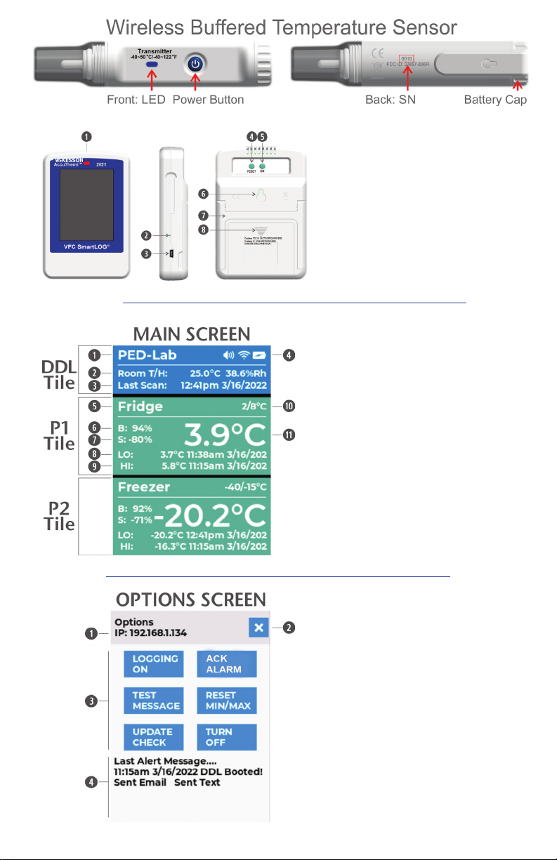
The McKesson refrigerator/freezer thermometer data logger (also referred to as SmartLOG in this document) is a Wi-Fi
digital data logger (DDL) that monitors and records temperature and sensor battery status for up to two wireless sensors.
It also logs the ambient room temperature/humidity and backup battery voltage.
The DDL scans for the wireless sensor in 1 minute intervals retrieving temperature, battery and signal data. This data
is evaluated for temperature excursions, low battery condition or no data which indicates signal loss from the wireless
sensor. If any of these conditions are true, the logger will send alerts via email and text message to contacts listed in
the settings page of the dashboard. If there is a temperature excursion, alarm LED and buzzer will sound. Logger then
refreshes the main DDL display screen and dashboard with all updated values. The SmartLOG dashboard can be viewed
using a web browser on a PC or smart phone. Monitor all DDL conditions, generate PDF reports, and modify settings.
using Dashboard (SmartLOG and PC or smart phone must be connected to same local network).
NOTE: If main power is lost, battery backup is provided by the 3 x AA batteries allow logging to continue for ~ 3 days
(depending on alerts) After approximately 4 hours the DDL will turn off the display and Wi-Fi radio to conserve power
allowing logging to continue until main power resumes. Tapping display will power screen for ~1 minute for viewing and
then go back off. The Web Dashboard will not be accessible until main power resumes. Alerts will continue to be sent
while on battery backup.
The wireless temperature sensor(s) LED blinks every 10 seconds, indicating sensor sent temperature, battery power,
and signal strength.
PRODUCT SETUP:
Wireless Temperature Sensor(s)
1. Install quantity 2 AAA batteries. To open turn clip cap counterclockwise 1/8 rotation.
2. Place batteries negative end in first.
3. To close align printed arrows on clip cap and sensor to each other, push in and twist 1/8 turn clockwise.
4. To power on wireless sensor, press power button until blue LED flashes 5 times. LED should flash once every 10
seconds. To power off sensor, press power button until LED flashes two times, then release button.
5. Take note of the four digit serial number on the backside of the sensor(s) and assign to intended P1/P2 in settings
page. e.g., P1 Name: Fridge SN# 000E
6. Place wireless sensor in storage unit to be monitored. Allow the sensor temperature to stabilize before setting up
DDL. (wait approx. 60 minutes)
SmartLOG Digital Data Logger (DDL)
NOTE: The following instructions are only necessary on the initial Start-up of SmartLOG. All configuration settings will
be retained in DDL memory.
1. Install quantity 3 AA batteries in compartment behind DDL. Slide cover down to open. Batteries are for backup
ONLY! Use wall 110VAC adapter as primary source of power.
2. Attach wall 110VAC adapter to DDL using USB cable and plug in AC adapter to wall outlet.
3. Push and hold ON button on back of SmartLOG DDL until beep sounds, then release.
4. Screen will show “Scanning For Networks” fig. 1
5. Then will change to “Select Network” when scan has completed. fig. 2
6. Tap using provided plastic stylus on “Select Network”
7. A drop-down “SSID’s” (Wi-Fi network names) will appear in location nearest to farthest order. fig. 3
8. Tap on your desired network name you want to connect to.
9. A password field and keyboard will appear, enter the wi-fi network password. fig. 4. Tap eye icon to see hidden typed
text if needed.
10. Tap the return key
on keyboard (lower right corner) to enter values. DDL will now connect to network.
11. If SmartLOG is able to make a connection to the network, a message will be displayed instructing to
complete remaining setup using a web browser. fig. 5 Follow “Dashboard” section to complete settings.
If SmartLOG is not able to connect to network it will return to line #4. Repeat network setup.
DASHBOARD:
1. In the address bar of a web browser fig. 6, enter “SmartLOG/” or the IP address displayed on DDL. fig. 5
Note: Host Name “SmartLOG” can be changed in settings page if desired.
2. On SmartLOG Dashboard page, click on the “Settings” (cog icon). A pop-up will appear, leave PIN field empty and
click “Open”.
3. The Settings Page will now open, customize SmartLOG for desired operation then click Save to complete
NOTE: The Access PIN field will require a 5 digit number in order to save the form. This PIN will be required for
future access to settings page.
4. When settings are saved the SmartLOG will automatically start booting. If an Update pop-up is displayed, ignore
unless there are new features you require or are having issues with SmartLOG. SmartLOG will continue booting
after 5 seconds.
5. Display will show boot messages Check Memory, Get Network Time, Set Time Zone, Send Alert Message ‘Booted’
and Then Scan for Temp(s) and then display Main Screen. fig. 7

5
SMARTLOG DASHBOARD
HOME PAGE
Navigation Icons
Logger Name, Alarm Spk, Wi-Fi, Pwr icons
Tap Spk to mute Alarm Buzzer on DDL
Sensor(s) Name
Temperature Gauge
relative to Min/Max set points
Current temperature
Min/Max settings values
Lowest and Highest recorded
Temperature, Date and Time
Sensor Battery power remaining
Signal strength
STATUS PAGE
Logger Information: Sensor serial number
Consecutive lost signals from wireless sensor,
Logging interval
Wi-Fi IP addr, Mac addr, Signal strength
CPU temperature, Ram used and free
Firmware version running
Support: Links to online manual, QuickStart
video, instructional video.
REPORT PAGE
Month: selection starts on 1st and reports to
last record of month.
Custom: user picks from/to dates for report.
Create: button generates the report
Report has 4 sections
1. Sensor Info
2. Daily Summary
3. Excursion Logs
4. Status/Alert Logs
5. Logs
All excursion values are color coded red for
high values, blue for low values
Print/Save: button opens print menu, select
save as PDF option to create a permanent file
on your PC.

SETTINGS PAGE ACCESS POPUP
Pin: 5 digit number
If created during initial setup enter Pin number,
otherwise, leave blank and click Open.
SETTINGS PAGE
Wi-Fi Setting
These fields are populated from the initial
SmartLOG SETUP.
To change network:
Network Name: SSID (Service Set Identifier)
is the name of your wireless network
Password: network password.
Username: is for Enterprise Networks.
LOGGER CONFIGURATION
Access Pin: 5 digit number (required to save)
Scale: Display & Report in °C or °F.
Log Interval: Select from 1 to 60 minutes.
Time Zone: Set your local Time Zone.
DST: Daylight Savings Time, sets clock forward
by one hour when checked.
Time is automatically synchronized from internet.
Logger Name: Name is used in reposts, emails &
SMS messages sent. Do not use the same name
if using additional data loggers on the same
network. Use up to 12 alphanumeric characters,
hyphen “-”, no spaces.
Facility Name: Location:, Pin or ID#: are optional fields that show on reports.
P1 & P2 Name: A drop down list to select Fridge or Freeze that will auto populate Alarm Temp: min and max values.
Custom name & min/max values can be entered. For single sensor application, leave P2 fields empty.
Sensor SN#: Enter serial number located on back of wireless sensor or new replacement sensor.
Cert Date: Enter calibration date from provided sensor certificate. Reports will display Cert. Expires date (+2 yrs).
State Data Upload
Logs can be sent daily directly to state VFC servers. Feature will be available in future update.
EMAIL FROM ACCT INFO
*see note ‘Office 365 accounts’
Email: Sign in to email for sending alerts
Password: Email account password
Outgoing SMTP: Dropdown list of popular email provider servers. Selecting a server name will auto populate the port #:
Custom server address & port # can be entered.
If Alerts and Status and message are not needed, leave Email From Acct fields empty.
Email/SMS Contacts
Email: Address to send alert email to.
SMS: 10 digit phone number to send text msg to.
Carrier: Select carrier of cell phone #. Select from dropdown list of popular cell phone carriers or enter custom value.
Daily Status Messages
Select one or both an am or pm time for daily notifications of sensor(s) current, min, max temps and battery level plus
ambient room temperature, humidity and SmartLOG battery state:
Time: can be set to OFF for both am and pm to disable status messages.

7
DDL OPTIONS SCREEN:
Tapping “Main” screen anywhere opens the “Options” screen. fig. 8
Tap X to close options screen if no change needed.
LOGGING BUTTON: When set to OFF, data recording will stop and alerts will be disable from being sent
NOTE: Alerts are sent every hour until alarm condition clears, or if logging is off.
LOGGING OFF
1. If button reads “LOGGING ON” it is in the ON state, logging data active.
2. Tap this button to turn LOGGING OFF. Wait for button to transition as email/SMS alerts are being sent out.
When alerts are complete, the screen will switch back to the main screen automatically showing DDL tile in red
and logger name replaced with “LOGGING OFF”.
LOGGING ON
1. If button reads “LOGGING OFF” it is in the OFF state, logging data stopped.
2. Tap this button to turn LOGGING ON. Wait for button to transition as email/SMS alerts are being sent out.
When alerts are complete the screen will switch back to the main screen automatically showing DDL tile blue and
“LOGGING OFF” replaced with logger name.
ACK BUTTON: When temperature excursion is acknowledged with the ACK ALARM button the audible buzzer will be
muted and an alert message will be sent. When alerts are complete, the screen will switch back to the main screen
automatically. Speaker icon will have an X indicating speaker is muted.

TEST MESSAGE BUTTON: Will send an email and/or SMS to recipients in contact list. Received message links will open
Dashboard in a browser.
1. Tap TEST MESSAGE button.
2. Tap YES in Confirm pop-up window will send a Test Email and SMS message then return to main screen. If you tap
NO, the pop-up will close and you will be sent back to main screen automatically.
RESET MIN/MAX BUTTON: Sets memory recorded min and max values to current temperature, time and date and re-
moves alert and alarm colors from display if excursion was triggered.
1. Tap RESET MIN/MAX button.
2. Tap YES in confirm pop-up window to reset values. Wait for button to transition as email/SMS alerts are being sent
out. Pop-up will close and switch back to the main screen automatically. If you tap NO, the pop-up will close and
will be sent back to main screen automatically.
UPDATE CHECK BUTTON: Checks online for new firmware. If new firmware is available, user has option to update.
NOTE: Only recommended if having issues or new features you require.
1. Tap UPDATE CHECK.
2. Taping YES in confirm pop-up window will download and install firmware then return to main screen. If you
tap NO, the pop-up will close and will be sent back to main screen automatically. Other responses: No Wi-Fi:
SmartLOG not connected to network, No Updates: SmartLOG is up to date.

9
TURN OFF BUTTON: Powers off SmartLOG.
1. Tap TURN OFF button.
2. Tap YES in confirm pop-up window to power off. Wait for button to transition as email/SMS alerts are being sent
out.
Confirm pop-up window “Powering Off In 5 Seconds”.
TROUBLESHOOTING GUIDE
Logger not powering on Check 5v adapter, USB cable, batteries
Not receiving wireless temperatures Check batteries and/or shorten distance between DDL and sensor
Data logger not responding Remove USB power and batteries; reinstall batteries and connect USB
power cord. Push on button until you hear beep. If no response data logger
may be faulty.
Incorrect Time Turn logger off. Start logger, will update from online time server.
Not able to connect to browser Name or IP must be entered in the ADDRESS BAR not SEARCH SmartLOG
DDL must be connected to same network as PC or smart phone
Unresponsive web page Click the refresh icon or press the F5 key for PC
Reset to factory Press RESET button on back of unit until you hear 2 beeps. Unit will reboot.
Will need to re-configure logger.
Email Response: Timed Out Was not able to connect to your email server, incorrect credentials, email
and/or password.

NOTE: Microsoft 365, Office 365, GoDaddy Office 365 and Gmail require additional settings in order to send emails and
SMS alerts from the SmartLOG DDL. Some of these setting require administrative rights to the email account to allow
SMTP, and be able to generate an APP PASSWORD that is used in place of your standard password. We recommend
using your standard email credentials as a starting point, SEND a Test Message and if you don’t receive the Test Message
then you might need to generate an APP PASSWORD and test again. If you still do not receive an Alert, an account
administrator will need to verify that SMTP is allowed for the account.
App Password for 365 account with multi-factor authentication (MFA) Enabled.
Sign into your 365 Account at https://portal.office.com.
In your account click icon in upper right corner, then click View Account.
On My Account page click Security info. On My Sign-Ins page click Add method.
Select App password. Click Add. Enter password Name (e.g. SmartLOG). Click Next.
Click pages icon to copy password to clipboard. Click Done.
Enter this password in settings page, Email From Acct Info, password field.
App password for Gmail account with 2-step verification enabled.
Sign into your Google account at https://accounts.google.com/login.
In account page, click select security on left side. In the sign in to Google box, click app passwords.
In app password, click select app and click other.
Then enter a name for the password (e.g. SmartLOG) and click generate.
The app password is the 16-character code in the yellow bar. Copy this password to Notepad or Word then click done.
Enter this password in settings page, Email From Acct Info, password field.

11
KIT CONSIST OF:
• 1 x Digital Data Logger
• 1 x Wireless Transmitter
• 1 x 5V 1A Power Adapter
• 1 x USB Cable
• 2 x AAA (for transmitter)
• 3 x AA (for DDL)
• 1 x Plastic Touch Screen Stylus
SPECIFICATIONS
SMARTLOG® DDL MONITOR GATEWAY
Wi-Fi: 802.11 b/g/n (2.4 GHz only)
Security: WPA/WPA2 Enterprise
Display: 240x320 pixel TFT Color Display w/Touch Screen
Screen Update: 60 seconds
Memor: 16MB (2 years of records @ 5 minute intervals)
Ambient Sensor: Temperature range -40 to +125°C (-40°F to 257°F), Humidity range
0-100%RH
Alarms: Audible Piezo Buzzer/Visual LED/SMS/Email
Date/Time: NTP clock synchronization during boot
Power: 5v wall adapter w/5’ micro USB cable
Batteries: Alkaline 1.5v 3 x AA (backup only for power loss)
Battery Life: ~ 3 days with no alarms, (NOTE: replace all batteries after any power loss of
more than 1 day)
Working Temp: -20 °C ~ 70 °C
Dimensions: 83 (W) X 120 (H) X 26 (D) mm,
WIRELESS BUFFERED TEMPERATURE SENSOR
Temperature Range: -40C to 50°C (-40°F to 122°F)
Accuracy: ±0.5°C (±1.0°F)
Distance: 50m/164ft (open field), 10m/32ft (inside fridge/freezer)
Buffer medium: Glycol
Batteries: Alkaline 1.5v 2 x AAA
Battery Life: ~1yr
Certification: 2yr NIST ISO17025 Certificate Included

Note:
This equipment has been tested and found to comply with the limits for a Class A digital device,
pursuant to part 15 of the FCC Rules. These limits are designed to provide reasonable protection
against harmful interference when the equipment is operated in a commercial environment.
This equipment generates, uses, and can radiate radio frequency energy and, if not installed
and used in accordance with the instruction manual, may cause harmful interference to radio
communications. Operation of this equipment in a residential area is likely to cause harmful
interference in which case the user will be required to correct the interference at his own expense.
Contains FCC ID: 2AC7Z-ESP32WROVERE
Contains IC: 2109-ESP32WROVERE
CAN ICES-003(A)/NMB-003(A)
DTS (Digital Transmission Systems) rules replace DSS (Direct Sequence Spread spectrum)
Warranty:
With respect to the goods, unless expressly agreed otherwise in writing, Thermco Products, Inc.
provides warranty for material and manufacturing defects for a period of one (1) year from date
of purchase. During said period, Thermco Products, Inc. offers to provide physical examination
of goods, provide repair of goods and/or components, or replace defective goods. This process
would be subject to Thermco Products, Inc. issuing a Return Goods Authorization (RGA), which
may or may not be at customer expense. Warranty shall not be considered for components such
as batteries, incompetent installation, faulty maintenance by customer, normal wear and tear or
deterioration of components due to improper use or non-compliance with proper use of goods.
10 Millpond Drive Unit #10 Lafayette, NJ 07848 - Phone: 973.300.9100
www.ThermcoProducts.com
Accreditation No.: 69071
to ISO/IEC 17025:2005
rev 04/27/2022


Table of contents
Popular Accessories manuals by other brands

Micro Motion
Micro Motion CMF Series instruction manual

Apogee Instruments
Apogee Instruments SQ-500 owner's manual

Rechner Sensors
Rechner Sensors Capacitive KAS-80 Series instruction manual

STEINEL
STEINEL L 86 Series manual

Hobbywing Technology
Hobbywing Technology G3 Advance Gyro user manual

PMK
PMK BumbleBee instruction manual