ACDC DCAC PI7803/3-MCB-GS User guide

Sur e Protection
G
Installation and Operating Instruction
EIGHT (8) STAGES 1/1 & 3/3SERIES PROTECTOR
Cascade bi-directional EMI-RFI filtering of phase (L) and neutral (N) wire
CLASS
CLASS
I+II+III
I+II+III
20
20
home
home
telecom
telecom
industry
industry
center
center
IT
IT
IP
IP
3
3
0
0
1
1
2
2
LPZ
LPZ
Single Phase & Three Phase CLASS I+II+III
Hard Wire Installation - Modular System
Sur
Sur eG
MULTI-STAGE SURGE PROTECTION
Empowered by Innovation
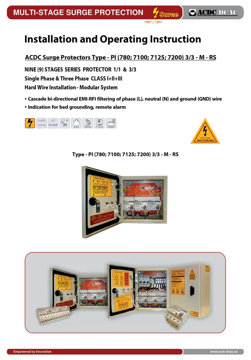
ACDC Surge Protectors Type - PI (780; 7100; 7125; 7200) 3/3 - MCB - GS
Type - PI (780; 7100; 7125; 7200) 3/3 - MCB - GS
Indication for bed grounding, remote alarm
www.acdc-dcac.eu

Mounting of ACDC Surge Protectors
ACDC Surge Protectors - Series have to be installed at ENTRY POINT the Main Distribution Boards (MDB)
or internal Sub Distribution Boards (SDB) right in front of the input power to the device that should be protected The ACDC Surge Protector
could be install in series or parallel configuration depending of total load per phase (>100A<).
- If the load per phase is <100A the ACDC Surge Protector install in SERIES configuration.
- If the load per phase is >100A the ACDC Surge Protector must be installed in PARALLEL configuration.
Type-PI 3/3 - MCB Green before Power
or .
have to be ed
Only in SERIES configuration all eight (8) protection stages are in function.
ACDC Surge Protectors are designed to fixed to the wall .
22
1.
If the the load per phase is <100A, our RECOMMENDATION is to install the surge protector in SERIES configuration
because only in this state your electrical devices will be fully protected.
If the total load per phase is >100A and ACDC Surge Protector is installed in PARALLEL configuration our
RECOMMENDATION is to install another ACDC Surge Protector in SERIES configuration ( Sub Distribution Board),
downstream power grid where the load per phase drops bellow 100A,
before
Condition for Installations:
Mounting:
Terminal and Wire size:
During the installation please check:
with screws
Each terminal is designed to accept wire sizes from 4mm to 25mm solid or stranded conductor.The wire insulation should be stripped back
8mm
The voltage of the ACDC Surge Protector matches actual system voltage.
2. All conductors are in accordance with the appropriate installation drawings.
THIS UNIT SHOULD BE INSTALLED AND SERVICED ONLY BY QUALIFIED PERSONNEL.
Before installing the ACDC Surge Protector, AC power must be OFF.
CORRECT INSTALLATION - THE LIGHTS GREEN ANDYELLOW ARE LIT
TROUBLESHOOTING - IF THE RED LED IS BLINKINGTHE GROUND WIRE IS NOT CONNECTED OR THE GROUND OF THE
POWER GRID SYSTEM IN NOT WELL PERFORMED
- rovides adequate electrical and safety protection
- Prevents the ingress of moisture and water
- Allows operating diagnostic status to be inspected
p
.
.
:
.
. ..
DANGER
CAUTION
!
!
CAUTION
!
!
CAUTION
!
!
Mounting of Protectors MULTI-STAGE SURGE PROTECTION
Sur
Sur eG
New materials, New design, New approach to Surge Protection Industry

L1
INPUT AC
L2 L3 NGnd L1 L2 L3 NGnd
up to
Circuit Breaker
100A C up to
100A C up to
100A C
NGnd
Terminal Blocks
L1 L2 L3 NGnd
OUPUT AC
Installation Instruction
Installation Instruction for Type - PI (780; 7100; 7125; 7200) 3/3 - MBS - GS
The Surge Protectors are installed in Metal Distribution board with degree of protection IP54
Circuit breakers MCB 100A are installed in the front of protectors for each phase
CAUTION
This equipment must only
be installed and serviced
by qualified electrical
personnel.
Turn off all power
supplying this equipment
before working on or inside
equipment.
During installation into an
electrical system, it must
not be energized until
completely inspection.
.
.
Failure to follow these
instructions will result
in serious injury.
HAZARD OF ELECTRIC
SHOCK, EXPLOSION, OR
ARC FLASH
DANGER
* G phase and neutral
out neutral for
WN
The Surge Protectors from series Type-PI 3/3-MBC- S are delivered with filtering as model basic
option. By customer request the model could be delivered for installation with filtering or parallel
installation with additional mark F and P
Installation Instruction
Sur
Sur eG
MULTI-STAGE SURGE PROTECTION
Integrated Multi-Stage Protection
www.acdc-dcac.eu

Operation
Diagnostic System
ACDC DCAC Dane Krapcev no.2/1, 1000-Skopje, Macedonia Phone: 389 2 3216 988; Fax: 389 2 3216 993
MULTI-STAGE SURGE PROTECTION
Sur
Sur eG
Every ACDC Surge ProtectorType -PI (740; 780; 7125; 7200) Green Series have free contact alarm as basic option. The alarm is activate in two cases:
1.When some of the protection stages (2, 4 or 6) are damaged or burned and Red Led is ON. Alarm contacts 1-3 are permanently closed.
2. When the ground of the power grid system is not well performed (pour grounding). Alarm contacts1-3 are closing with frequency of 2Hz (0,5s)
Red led is blinking.
Free contacts are on the cover of the protector with contact no. 1 and 3. (see picture)
The contact is a optocoupler with maximum value of voltage 70VDC and current of 10mA. In normal condition it is open.
.
.
13
N.C
+
-
Free Contact Alarm
Connection for ommon ontact larms c c a
Series
ACDC SURGE PROTECTOR
Green
MULTI-STAGE
SURGE
PROTECTION
CLASS I II III++
1, 3 and 7 Stage: Filter (bi-directional wave tracking);
3dB-3kHz,38dB-100kHz,50dB-300kHz; 50bB-500kHz
2, 4 and 5 Stage: Surge Limiter (L-N)
150kA (8x20
150kA (8x20
s); 22kA (10/350
s); 22kA (10/350
s)
s)
6. Stage: MOSFET Limiter-500A (8x20
s)(RT<1ns)
s)(RT<1ns)
8. Stage: Surge Limiter (N-Gnd)
125kA (8x20
125kA (8x20
s); 20kA (10/350
s); 20kA (10/350
s)
s)
μ μ
μ
μ μ
EP S
IGHT ROTECTION TAGES
Load Rating: 230VAC@ 100A
Type - PI Green SeriesType - PI Green Series
L
N
IN
IN
N
PARALLEL
L
OUT
NN
PARALLEL
L
OUT
GGNDND
FAULTFAULT
L
G
II
II
CORRECTCORRECT
OUT
IV,VIIV,VI
ND
CORRECTCORRECT
Series
ACDC SURGE PROTECTOR
Green
MULTI-STAGE
SURGE
PROTECTION
CLASS I II III++
N
1, 3 and 7 Stage: Filter (bi-directional wave tracking);
3dB-3kHz,38dB-100kHz,50dB-300kHz; 50bB-500kHz
2, 4 and 5 Stage: Surge Limiter (L-N)
150kA (8x20
150kA (8x20
s); 22kA (10/350
s); 22kA (10/350
s)
s)
6. Stage: MOSFET Limiter-500A (8x20
s)(RT<1ns)
s)(RT<1ns)
8. Stage: Surge Limiter (N-Gnd)
125kA (8x20
125kA (8x20
s); 20kA (10/350
s); 20kA (10/350
s)
s)
μ μ
μ
μ μ
Load Rating: 230VAC@ 100A
L
EP S
IGHT ROTECTION TAGES
Type - PI Green SeriesType - PI Green Series
IN
IN
PARALLELPARALLEL
N
L
OUT
NN
PARALLELPARALLEL
L
OUT
GGNDND
FAULTFAULT
L
G
II
II
CORRECTCORRECT
OUT
ND
IV,VIIV,VI
CORRECTCORRECT
Series
ACDC SURGE PROTECTOR
Green
MULTI-STAGE
SURGE
PROTECTION
CLASS I II III++
NN
1, 3 and 7 Stage: Filter (bi-directional wave tracking);
3dB-3kHz,38dB-100kHz,50dB-300kHz; 50bB-500kHz
2, 4 and 5 Stage: Surge Limiter (L-N)
150kA (8x20
150kA (8x20
s); 22kA (10/350
s); 22kA (10/350
s)
s)
6. Stage: MOSFET Limiter-500A (8x20
s)(RT<1ns)
s)(RT<1ns)
8. Stage: Surge Limiter (N-Gnd)
125kA (8x20
125kA (8x20
s); 20kA (10/350
s); 20kA (10/350
s)
s)
μ μ
μ
μ μ
EP S
IGHT ROTECTION TAGES
Load Rating: 230VAC@ 100A
Type - PI Green SeriesType - PI Green Series
L
IN
ININ
NN
PARALLEL
L
OUTOUT
PARALLEL
NN
L
OUT
GGNDND
FAULTFAULT
L
G
II
II
CORRECTCORRECT
OUT
IV,VIIV,VI
ND
CORRECTCORRECT
mark
mark
mark
13
+
-
Operation Diagnostic System
Led Indication for correct stage no. 2,4 and 6. The
.
stages no. 1,3 and 7 (high
garde bi-directional filtering) are always in function along with ultimate (5-th)
protection stage
Led Indication for correct stage no. 4,6 and un correct no 2. The
.
stages no. 1,3
and 7 (bi-directional filtering) are always in function along with ultimate (5-th)
protection stage
Only stages 1,3 and 7 are still in function along with ultimate (5-th) protection
stage.
Led Indication for bed grounding (Low impedance equipotential ground is not
provided)
Normal:
Fault:
Fault:
Fault:
Red Yellow Green
Continuous yellow
and green
Continuous green
Blinking red
Continuous red
This manual suits for next models
3
Other ACDC DCAC Surge Protector manuals
Popular Surge Protector manuals by other brands

resideo
resideo R8184G installation instructions

Total Protection Solutions
Total Protection Solutions ComTrack TK-CT2-PHONE-RJ Installation, operation and maintenance instructions

Eaton
Eaton PH Series installation instructions

Gembird
Gembird SIS-TUV user manual

CyberPower
CyberPower HT705UC user manual

Liebert
Liebert Liebert LPGE Series Technical specifications