Acer AL1731 User manual

Monitor AL1731
Service Guide
Service guide files and updates are available
on the AIPG/CSD web; for more information,
please refer to http://csd.acer.com.tw

1
CONTENTS
1. INTRODUCTION .......................................................................................................................................... 3
1.1 Scope .................................................................................................................................................................... 3
1.2 Description ........................................................................................................................................................... 3
2. ELECTRICAL REQUIREMENTS................................................................................................................. 4
2.1 Standard Test Conditions ..................................................................................................................................... 4
All tests shall be performed under the following conditions, unless otherwise specified............................................. 4
2.2 LCD monitor General specification ..................................................................................................................... 4
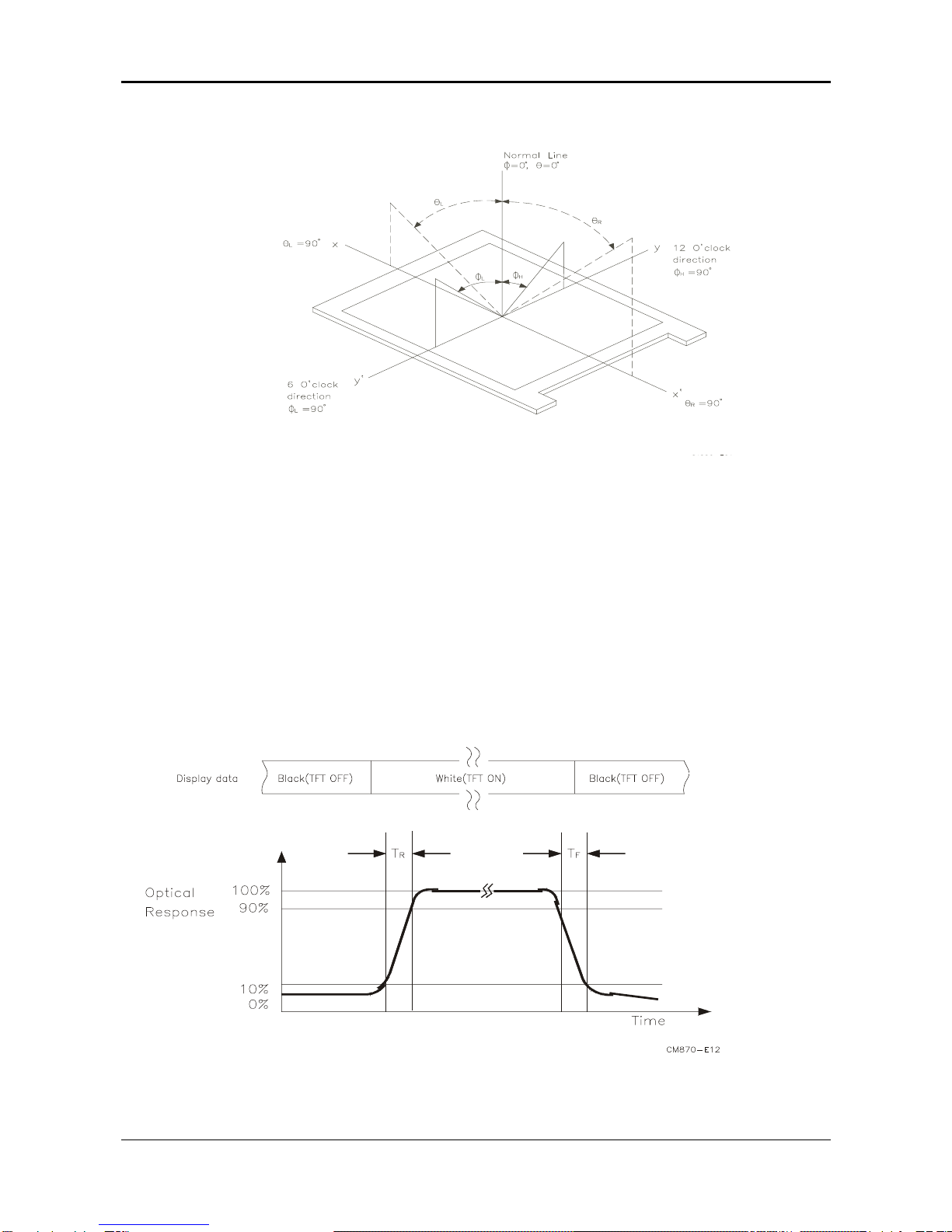
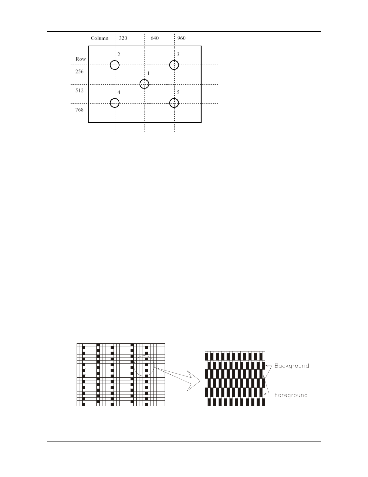
2.3 LCD Panel Specification ...................................................................................................................................... 5
2.4 Input Signals....................................................................................................................................................... 11
2.5 CONTROLS ........................................................................................................................................................ 15
2.6 White Color Temperature................................................................................................................................... 19
2.7 POWER SUPPLY ............................................................................................................................................... 20
2.8 Plug & Play (EDID) ........................................................................................................................................... 22
2.9 Audio Technical specification ............................................................................................................................ 23
3. VL-903 DISPLAY CONTROL BOARD...................................................................................................... 24
3.1 Description ......................................................................................................................................................... 24
3.2 Features.............................................................................................................................................................. 24
3.3 BLOCK DIAGRAM ............................................................................................................................................ 25
3.4 Connector Locations .......................................................................................................................................... 26
3.5 Connector Type .................................................................................................................................................. 26
3.6 Connector pin assignment .................................................................................................................................. 27
4. VK-903 Function Control key Board....................................................................................................... 30
4.1 Description ......................................................................................................................................................... 30
4.2 Connector and Switch Locations........................................................................................................................ 30
4.3 Connector type.................................................................................................................................................... 30
4.4 Connector pin Assignment.................................................................................................................................. 30
4.5 Switch definition ................................................................................................................................................. 31
4.6 LED definition .................................................................................................................................................... 31
5. TROUBLESHOOTING............................................................................................................................... 32
5.1 Main Procedure.................................................................................................................................................. 32
6. MECHANICAL REQUIREMENTS ............................................................................................................. 37
6.1 Vibration and Shock ........................................................................................................................................... 37
6.2 Package Drop Specification ............................................................................................................................... 37
6.3 Dimension Size and Weight................................................................................................................................38
6.4 Tilt Base Rotation ............................................................................................................................................... 40
6.5 Plastic Material .................................................................................................................................................. 40
6.6 GAP Spec............................................................................................................................................................ 40
7. Power Line Transient Test (IEC 61000-4-4 Fast Transients/Burst) ..................................................... 40
7.1 Peak Voltage: ..................................................................................................................................................... 40
7.2 Polarity : + / - ............................................................................................................................................. 41
7.3 Repetition Frequency of the impulse : 5 KHz..................................................................................................... 41
7.4 Rise-Time : 5ns
±
30% ..................................................................................................................................... 41
7.5 Impulse Duration: 50 nS
±
30%......................................................................................................................... 41
7.6 Relation to Power Supply: Asynchronous .......................................................................................................... 41
7.7 Burst Duration: 15 ms
±
20% ............................................................................................................................ 41
7.8 Burst Period: 300 ms
±
20% .............................................................................................................................. 41
7.9 Climatic Conditions: .......................................................................................................................................... 41
7.10 Test Procedure: .................................................................................................................................................. 41
8. Power Line Surge Test (IEC 61000-4-5 Surge) ...................................................................................... 43
8.1 Climatic Condition ............................................................................................................................................. 43
8.2 Test Conditions:.................................................................................................................................................. 43
8.3 The surge will be applied between lines and between lines and ground ........................................................... 43
8.4 If not otherwise specified, the surge to power supply circuits shall be applied synchronized .......................... 43
8.5 The surge voltage for test is from 1 KV and increases 1 kV for each step ........................................................ 43
8.6 The recommended severity levels for the surge voltage test is 2.0 KV ............................................................. 43
8.7 Display set high-resolution mode, AC input use AC 240V................................................................................ 43
9. ENVIROMENT REQUIREMENT................................................................................................................ 44
9.1 Operating............................................................................................................................................................ 44

2
9.2 Storage or Shipment ........................................................................................................................................... 44
10.REGULATION COMPLIANCE .................................................................................................................. 45
10.1 This product comply to the most current revisions of following regulations: .................................................... 45
10.2 Electrostatics Discharge (ESD).......................................................................................................................... 46
11.QUALITY AND RELIABILITY.................................................................................................................... 47
11.1 Quality Assurance .............................................................................................................................................. 47
11.2 Reliability ........................................................................................................................................................... 47
12.Part List ..................................................................................................................................................... 48
Appendix A: Display Unit Assembly------------------------------------------------------------------------------------------------50
Appendix B: P.C.B.A ASSEMBLY-------------------------------------------------------------------------------------------------60

3
1. INTRODUCTION
1.1 Scope
This specification defines the requirements for the 17” MICRO-PROCESSOR based Multi-
mode supported high resolution color LCD monitor, Monitor can be directly connected to
general 15 pin D-sub VGA connector and DVI-D digital connector, eliminates the
requirement of optional special display card. It also supports VESA DPMS power
management and plug & play function. There is a build-in stereo audio amplifier with
volume control to drive a pair of speakers. Monitor also can support multi-media function as
Composite signal and S-Video signal input.
1.2 Description
The LCD monitor is designed with the latest LCD technology to provide a performance
oriented product with no radiation. This will alleviate the growing health concerns. It is also
a space saving design, allowing more desktop space, and comparing to the traditional CRT
monitor, it consumes less power and gets less weight in addition MTBF target is 20k hours
or more.

4
2. ELECTRICAL REQUIREMENTS
2.1 Standard Test Conditions
All tests shall be performed under the following conditions, unless otherwise specified.
Ambient light: 225 lux
Viewing distance : 50 cm in front of LCD panel
Warrn up time
All specifications: 30 minutes
Fully functional: 5 seconds
Measuring Equipment: Chroma 2250 signal generator or equivalent, directly
Connected to the monitor under test.
Minolta CA100 photometer, or equivalent
Control settings
User brightness control: Maximum (unless otherwise specified )
User contrast control: Typical (unless otherwise specified )
User red/white balance,
Green/white balance and
Blue/white balance control: In the center (unless otherwise specified )
Power input : 110Vac or 230Vac
Ambient temperature : 20 ±5 ˚C ( 68 ±9 ˚F)
Analog input mode : 1280 x1024 /60 Hz
2.1.1 MEASUREMENT SYSTEMS
The units of measure stated in this document are listed below:
1 gamma = 1 nano tesla
1 tesla = 10,000 gauss
cm = in x 2.54
lb = kg x 2.2
degrees F = [°C x 1.8] + 32
degrees C = [°F - 32]/1.8
u' = 4x/(-2x + 12y + 3)
v' = 9y/(-2x + 12y + 3)
x = (27u'/4)/[(9u'/2) - 12v' + 9]
y = (3v')/[(9u'/2) - 12v' + 9]
nits = cd/(m2) = Ft-L x 3.426
lux = foot-candle x 10.76
2.2 LCD monitor General specification
Panel Type : 17 “ active matrix color TFT LCD
1). Hydis HT17E12-200
Display size : 337.92mm(H) x 270.34mm(V)
Display mode : VGA 720 X 400 (70 Hz)
VGA 640 X 480 (60/70/75 Hz)
SVGA 800 X 600 (60/70/75 Hz)
XGA 1024 X 768 (60/70/75 Hz)
SXGA 1280 X 1024 (60/70/75 Hz) standard resolution

5
Pixel pitch : 0.098x3mm(H) x 0.294mm(V)
Display Dot : 1280 x (RGB) x 1024
Pixel Clock : 25.2 – 135.0MHz
Contrast ratio:
θ
= 0˚Hydis 430:1 (conditions = typical).
Brightness: Hydis: 250 cd/m²(conditions= typical).
Response time (Tr/Tf): Hydis(20) (conditions Ta=25℃).
Display color : Hydis: 16.2M (6bitecolor+FRC)
Viewing angle: Hydis
L / R ≧80 / ≧80 ( ≧160 degrees horizontal typical)
U / D ≧65 / ≧65 ( ≧130 degrees vertical typical)
Luminance Uniformity : > 75 %
Pc interface: 1). Video : RGB analog 0.7V peak to peak
Sync : TTL positive or negative
2). Digital : TMDS
3). Audio : 3.5 mm stereo audio jack (Audio)
Signal connector : 15 pin Mini D type, (standard VGA video)
DVI-D connector
Audio power : 1Wrms + 1Wrms ( 300Hz – 10kHz (S.P.L. – 10 dB))
Front control : power on/off with LED select (up, down) adjustment (+,-)
Interface frequency
Horizontal Frequency 30KHz --80KHz(analog), 31.5– 64KHz(digital)
Vertical Frequency 56Hz ----75Hz
Plug & play : Support VESA DDC2B functions
Power Input voltage : Single phase, 50/60HZ, 100VAC to 240VAC ±10%
Total output power : 56 Watt max.
2.3 LCD Panel Specification
2.3.1 LCD Panel Model (Hydis HT17E12-200)
• Display Type active matrix color TFT LCD
• Resolution 1280 x 1024 pixels
• Display Dot 1280x (RGB) x 1024
• Display Area 337.92mm(H) x 270.34mm(V)
• Pixel Pitch 0.264mm(H) x 0.264mm(V)
• Display Color 16.2M (6 bite color+FRC)

6
• Lamp Voltage 700 Vrms (typ)
• Lamp Current 6.5 mArms ( typ)
• Weight 1900g ( MAX)
• Optical Specifications
The following items are measured under stable conditions. The optical characteristics
should be measured in a dark room or equivalent state with the methods shown in
Note(4).
Measuring equipment : TOPCON BM-5A, BM-7, PHOTO RESEARCH PR650
(Inverter Freq. : 54kHz) *Ta =25 ±2°C, VDD=5V, fv=60 Hz, fDCLK=54 MHz, IL= 6.5mArms
ITEM Symbol Condition MIN. TYP. MAX. UNIT
Contrast Ratio
(Center of screen)
CR
350
430
-
Rising TR 5Response
Time at Ta Falling TF
- 15 30 (total)
msec
Luminance of white
(Center of screen)
YL
-
250
-
cd/m2
RX 0.599 0.629 0.659
Red RY 0.324 0.354 0.384
GX 0.257 0.287 0.317
Green GY0.568 0.598 0.628
BX0.115 0.145 0.175
Blue BY0.073 0.103 0.133
WX0.270 0.300 0.330
Color
Chromaticity
(CIE)
White WY
φ=0,
θ=0
Normal
Viewing
Angle
0.305 0.335 0.365
θL- 80 -
Hori. θR- 80 -
φH - 65 -
Viewing
Angle
Vert. φL
CR≥10
- 65 -
Degrees
Brightness Uniformity BUNI - - 1.2
Flicker F - - 5 %
Cross talk CT - - 20 %
*For Edge shadow will follow limit sample to check.

7
Note 1) Definition of Viewing Angle: Viewing angle range (10≤CR)
Note 2) Definition of Contrast Ratio (CR): Ratio of gray max(Gmax),gray min(Gmin) at the
center point of panel.
Luminance with all pixels white (Gmax)
CR=
Luminance with all pixels black (Gmin)
Note 3) Definition of Response time: Sum of TR , TF
Note 4) After stabilizing and leaving the panel alone at a given temperature for 30 min,
the measurement should be executed .Measurement should be executed n a
stable, windless ,and dark room.30 min after lighting the back-light. This
should be measured in the center of screen. Dual lamp current :13.0mA(6.5mA

8
x2)(Refer to the note(1) in the page 14 for more information ).
Environment condition :Ta=25±2°C
Optical characteristics measurement setup
Notes 5) Definition of Luminance of White : measure the luminance of white at center point.

9
○is test point.
Notes 6)Definition of 9 points brightness uniformity (Measuring points: Refer to the Note 5)
Bmin
BUNI=100∗
Bmax
Bmax: Maximum brightness
Bmin: Minimum brightness
Notes 7) Definition of Flicker level
Flicker Voltage pp
F = x 100 %
LMD Voltage dc
♦ One maximum value of three estimated values.
♦ For this test ,an LMD(Light Measurement Device)is needed with adequate response time
to track any visible rate flicker component and with a voltage level output proportional
To luminance intensity.
♦ Test Pattern: For dot inversion Driving(Gray levels of foreground dots on the test panel
Are G22,G32,and G45)
♦ Test Point :Center point of the display area

10
Note 8) Definition of Crosstalk (Refer to the VESA STD)
The calculation for shadowing is made from the 2 luminance measurements Gbkg and Lsh,
as follows:
Lmax-Lmin
C
T = x100 %
Lmin
Where Lmax is the larger value of Gbkg or Lsh , and Lmin is the smaller of the two.
♦To determine background and foreground levels (colors),first set the background to any
gray scale or color level suitable for shadowing determination.(Note that it may take
several iterations of adjusting background level and box levels to determine the proper
value for the background .Next display the box levels to determine the proper value for the
background level. Look for shadowing in any direction from box E. Independently vary the
gray level (or color) of the background and box E until the worst case shadowing is
observed. This defines the background (Gbkg) and foreground (Gfg) levels to be
maintained for the remainder of the test.
♦One point only (the target) will be measured. To determine that point proceed as follows
Using the background and foreground gray levels of step1 (Gbkg and Gfg). Turn on each
box at a time. Look for the case with the worst shadowing. The box causing the worst case
is the shadowing source, or Bsrc. Use Bsrc and the box opposite from it that lies directly in
the shadow path. That is the target box, or Btgt. Note that box Eight be either Bsrc or Btgt,
depending on the shadowing conditions, but typically Bsrc and Btgt will be a pair of
opposite boxes, A&C or B&D. Btgt will only be displayed for aligning the LMD. It will be
turned off for the actual measurement.
♦ The target box point (Btgt) will be measured with the source box (Bsrc) turned on then off.
(Btgt is for alignment purpose only) Display the background only at level Gbkg. Display
Btgt determined in step 2 above. Using the correct distance, angle, and measurement
aperture, align the LMD to the center of the Btgt. Turn off Btgt. With Gbkg set to its proper
level, measure the luminance (or color). Next,turn on the source box Bsrc. Again measure
at the center point of Btgt (without Btgt present.). In this case the LMD will be measuring
the shadowing level, Lsh.

11
2.4 Input Signals
2.4.1 Video input
• Type Analog R, G, B., Digital TMDS
• Input Impedance 75 ohm +/- 2%
• Polarity Positive
• Amplitude 0 - 0.7 +/- 0.05 Vp
• Display Color same as LCD panel
2.4.2 Sync input
• Signal separate horizontal and vertical sync, or composite sync
which are TTL compatible
• Polarity positive and negative.
2.4.3 Interface frequency
The following frequency range is generalized by supported timing. If the entered
mode does not match the supported timing the display optimization will not be
assured.
• Horizontal Frequency 30KHz --80KHz(analog), 31.5– 64KHz(digital)
• Vertical Frequency 56Hz ---------75Hz
DISPLAY MODES
MONITOR
MODE NO.
SCREEN
RESOLUTION
HORIZONTAL
SYNC RATE
(kHz)
VERTICAL
SYNC RATE
(Hz)
VIDEO CLK
(MHz)
STANDARD
1 640X480 31.5 - 60.0 - 25.0 Defacto
2 640X480 37.86- 72.80- 31.5 VESA
3 640X480 37.5- 75.0- 31.5 VESA
4 720X400 31.5 - 70.0 + 28.0 Text Defacto
5 800X600 37.8 + 60.0 + 40.0 VESA
6 800X600 48.07 + 72.18 + 50.0 VESA
7 800X600 46.87+ 75.0+ 49.5 VESA
8 1024X768 48.4 - 60.0 - 65.0 VESA
9 1024X768 56.47 - 70.07 - 75.0 VESA
10 1024X768 60.0 + 75.0 + 78.75 VESA
11 1280X1024 64.0 + 60.0 + 108.5 SXGA
12 1280X1024 80.0 + 75.0 + 135.0 SXGA

12
Supported Timing
TIMING FH(KH
Z)
SYNC TOTAL ACTIVE SYNC FRONT BACK PIXEL
FV(HZ) POLARITY (DOT/LINE) (DOT/LINE) WIDTH PORCH PORCH FOREQ.(MHZ)
(DOT/LINE) (DOT/LINE) (DOT/LINE)
640x480 31.469 – 800 640 96 16 48 25.175
VGA-480 59.94 – 525 480 2 10 33
640x480 37.861 – 832 640 40 16 120 31.5
VESA-480-72Hz 72.809 – 520 480 3 1 20
640x480 37.5 – 840 640 64 16 120 31.5
VESA-480-75Hz 75 – 500 480 3 1 16
720x400 31.469 – 900 720 108 18 54 28.322
VGA-400-TEXT 70.087 + 449 400 2 12 35
800x600 37.879 + 1056 800 128 40 88 40
VESA-600-60Hz 60.317 + 628 600 4 1 23
800x600 48.077 + 1040 800 120 56 64 50
VESA-600-72Hz 72.188 + 666 600 6 37 23
800x600 46.875 + 1056 800 80 16 160 49.5
VESA-600-75Hz 75 + 625 600 3 1 21
1024x768 48.363 – 1344 1024 136 24 160 65
XGA 60.004 – 806 768 6 3 29
1024x768 56.476 – 1328 1024 136 24 144 75
VESA-768-70Hz 70.069 – 806 768 6 3 29
1024x768 60.023 + 1312 1024 96 16 176 78.75
VESA-768-75Hz 75.029 + 800 768 3 1 28
1024x1024 64 + 1688 1280 112 48 248 108
VESA-1024-60Hz 60 + 1066 1024 3 1 38
1280x1024 80 + 1688 1280 144 16 248 135
VESA-1024-75Hz 75 + 1066 1024 3 1 38
If the input timing is not a supported timing listed above but within the supported frequency
range (Horizontal: 80KHz,Vertical: 75Hz), this monitor will select a closest mode instead. But
the display quality may not be optimized.
If the input timing over the supported frequency range, a message “Input Signal Out of Range”
will be shown.
2.4.4 Support Modes
There will be 12 total support modes to accommodate the above mode and other video
modes within the frequency range of the monitor.
Analog R, G, B. MAX supports range 1280x1024 75Hz.
Digital TMDS MAX supports range 1280x1024 60Hz.

13
2.4.5 85Hz refresh rate Support
Monitor should display 85Hz refresh rate mode as emergency mode.
Monitor should display “Out of Range” warning menu at this mode.
2.4.6 Analog Video input Connector
Analog Video input Connector: 15pins mini D-Sub
Table 2.4.5. Pin assignment for D-sub connector
PIN
NO.
Separate Sync
1 RED VIDEO
2 GREEN VIDEO
3 BLUE VIDEO
4 GROUND
5 GROUND
6 RED GROUND
7 GREEN GROUND
8 BLUE GROUND
9 PC5V (+5V DDC)
10 CABLE DETECTION
11 GROUND
12 SDA
13 H.SYNC
14 V.SYNC
15 SCL
15
10
5 1
6
11
D-sub connector
Color of plastic parts: Blue

14
Digital Video input Connector: DVI-D (T.B.D)
Table 4-3-3. Pin assignment for DVI-D (24pin) connector
Pin – Assignment of DVI –D connector :
1 TX2- 9 TX1- 17 TX0-
2 TX2+ 10 TX1+ 18 TX0+
3 Shield (TX2 / TX4) 11 Shield (TX1 / TX3) 19 Shield (TX0 / TX5)
4 NC 12 NC 20 NC
5 NC 13 NC 21 NC
6 DDC-Serial Clock 14 +5V power *) 22 Shield (TXC)
7 DDC-Serial Data 15 Ground (+5V) 23 TXC+
8 No Connect 16 Hot plug detect 24 TXC-
*) In case, the power of the PC unit is switched off and the power of the monitor is switched on,
no voltage may occur at pin 14.
Composite Video: Monitor rear side RCA female (Yellow).
AV1-input
S-Video (Y/C): Monitor rear side 4 Pin Mini-DIN female.
S-Video
2.4.7 Support Composite Video & S – Video Input:
JV3 for Composite Video RCA female (Yellow)
JV4 for S-Video female (Black)
Composite/S-VIDEO INPUTS
S-Video Type Y/C : NTSC/PAL
Level 0.7Vpp

15
Impedance 75 ohm terminated
Composite Video Type Composite : NTSC/PAL
Level 0.7Vpp
Impedance 75 ohm terminated
2.5 CONTROLS
A brief description and the location of all LCD Monitor functions controls and indicators:
Figure 2-1
1 Stereo Speakers PC Audio Stereo output.
2
Soft Power Switch
(DC Power-On
Indicator)
1. Press the soft power switch to switch the monitor ON/OFF.
2. LED lights Blue color --- Power is ON.
3. LED lights Yellow --- Monitor is in "Power Saving Mode".
4. LED is off --- Power is OFF.
3 Auto
1. Press the Auto Buttons Monitor will Auto-Adjusting.
2. Press the Auto Buttons over 2 second the Monitor Searching next
source.
4
Function Select and
Adjustment Control
Buttons
1. Direct press either left or right control button can adjusting speaker
Volume control.
2. When press after Menu buttons then Press either left or right control
button for OSD first menu (left side) function selection.
1. When selection you want adjusting function then press Menu
buttons again for OSD second menu (right side) function selection.
You can Press the left button to decrease the OSD setting and press
the right button to increase the OSD setting.
5 Menu
1. Press the Menu will show OSD (On Screen Display) Function
Menus table.
2. When OSD (On Screen Display) Menus display press Menu
Buttons will enable selection function.

16
2.5.1 Adjusting the Monitor’s Display
The monitor has four function control buttons to select among functions shown on OSD menu,
designed for easy user-viewing environments.
OSD Function Menu
To access OSD Main menu, simply press one of the
Function Select control buttons, and the menu diagram will
pop up on the screen as shown on Fig. 2-2:
Continue pressing the Function Select buttons to scroll
through the entire menu items ,then press Adjustment
Control buttons to adjust content of selected item.
Figure 2-2
2.5.2 Function Description
2.5.2.1.1.1 Analog RGB / Digital RGB
Picture
Auto adjust Press > button, auto adjust the display mode to its utmost performance
according to VGA setting.
Brightness Adjust the overall image and background screen brightness.
Contrast Adjust the image brightness in relation to the background.
H-position To move the picture image horizontally left or right.
V-position To move the picture image vertically up or down.
Phase To improve focus clarity an image stability.
Clock To increase or decrease the horizontal size of image.
Exit To exit the main menu.
Advanced
Sharpness Adjusts the picture sharpness.
Color You have 4 kinds of options.
Cool
This control adjusts the color temperature of the screen image, this item
are preset by factory, you can not adjust these setting, The performance is
bluer and brighter.
Natural This performance is reddish and closer to paper white.
Warm This performance is yellowish and closer to paper white.
User You can adjust the individual color intensity by yourself. Increase or
decrease red, green or blue depending upon which is selected
User red Increase or decrease red.
User green Increase or decrease green.
User blue Increase or decrease blue.
Exit To exit the main menu.
Audio
Volume This features adjusts < to decrease volume and > to increase volume.
Base This features adjusts < to decrease base and > to increase base.
Treble This features adjusts < to decrease treble and > to increase treble.
ATTL This features adjusts < to decrease left speaker volume and > to increase
left speaker volume.
ATTR This features adjusts < to decrease right speaker volume and > to increase
right speaker volume.
Loudness This features choose on or off to get loudness.
Mute This features choose on or off to mute the sound.
Exit To exit the main menu.
Options
OSD To move the OSD image.
OSD H-position To move the OSD image horizontally left or right.

17
OSD V-position To move the OSD image vertically up or down.
Language You can choose one of the nine languages you need.
Exit To exit the main menu.
Utilities
OSD timeout
You can select how long the monitor waits after the last adjust of the key
to shut off the OSD menu. The time setting choices are from 5 to 60
seconds.
OSD background You can select opaque or translucent to change OSD background.
Source icon You can select on or off to display OSD icon.
Exit To exit the main menu.
Reset
Memory recall Reset the currently highlight control to the factory setting. User must be
using factory preset video mode to use this function.
Exit To exit the menu.
Exit To exit the OSD menu.
Composite Video / S-Video
Picture
Brightness Adjust the overall image and background screen brightness.
Contrast Adjust the image brightness in relation to the background.
Saturation Adjusts the color saturation of the screen image.
Hue Adjusts the color hue of the screen image.
Sharpness Adjusts the picture sharpness.
Scaling Adjusts the picture size full screen or 16:9 screen.
Exit To exit the main menu.
Advanced
Sharpness Adjusts the picture sharpness.
Color You have 4 kinds of options.
Cool
This control adjusts the color temperature of the screen image, this item
are preset by factory, you can not adjust these setting, The performance is
bluer and brighter.
Natural This performance is reddish and closer to paper white.
Warm This performance is yellowish and closer to paper white.
User You can adjust the individual color intensity by yourself. Increase or
decrease red, green or blue depending upon which is selected
User red Increase or decrease red.
User green Increase or decrease green.
User blue Increase or decrease blue.
Exit To exit the main menu.
Audio
Volume This features adjusts < to decrease volume and > to increase volume.
Base This features adjusts < to decrease base and > to increase base.
Treble This features adjusts < to decrease treble and > to increase treble.
ATTL This features adjusts < to decrease left speaker volume and > to increase
left speaker volume.
ATTR This features adjusts < to decrease right speaker volume and > to increase
right speaker volume.
Loudness This features choose on or off to get loudness.
Mute This features choose on or off to mute the sound.
Exit To exit the main menu.
Options

18
OSD To move the OSD image.
OSD H-position To move the OSD image horizontally left or right.
OSD V-position To move the OSD image vertically up or down.
Language You can choose one of the nine languages you need.
Exit To exit the main menu.
Utilities
OSD timeout
You can select how long the monitor waits after the last adjust of the key
to shut off the OSD menu. The time setting choices are from 5 to 60
seconds.
OSD background You can select opaque or translucent to change OSD background.
Source icon You can select on or off to display OSD icon.
Exit To exit the main menu.
Reset
Memory recall Reset the currently highlight control to the factory setting. User must be
using factory preset video mode to use this function.
Exit To exit the menu.
Exit To exit the OSD menu.
Sharpness : Adjust the scale-up effect(smoother or sharper.)
OSD Transparency: Adjust the transparency level of OSD. The range is from 0 to 100 scales.
Comment:
• 1280x1024: Current mode resolution.
• 60 HZ: Current mode vertical frequency±1Hz.
• VER 1.00: Firmware revision.
Other features:
Intellectual-Auto AM737 can start the Auto-Adjustment automatically when input a new
display mode at first time less then 4 sec to finish. After the adjustment, AM737 will
remember this mode and switch to optimized condition automatically for this mode
whenever encounter this mode again.
The 640×400, 720×400 mode can do graph/ text select on OSD Advanced function.
Total 13 recent used modes are recorded into EEPROM. If other support modes input to
monitor EEPROM will cancel by first in first out motion.
After finishing adjustment from OSD, the data need 3 sec to save NVRAM memory.
VESA DPMS Functionality When signaled by the host CPU, AM737 show a black
screen about 5 seconds. If no further signal, then it shows “No Signal” and enter power
saving mode.

19
2.6 White Color Temperature
White color temperature is 4 preset as 9300, 7500,6500 and User,
Default value of user color should be user which is maximum setting for panel.
Target of color setting
Color Temp. Color Coordinate Tolerance Color Coordinate Tolerance
x y u’ v’
Cool (9300K) 0.283 0.297 +0.03 0.189 0.446 u’v’ < 0.01*
Natural (6500K) 0.313 0.329 +0.01 0.198 0.468 u’v’ < 0.01*
Warm (5000K) 0.346 0.359 +0.03 0.209 0.488 u’v’ < 0.01*
User - - - - -
*) TCO’0X A.2.6.1 requirement
User should follow “Microsoft Windows Color Quality Specification for Liquid Crystal Display OEM’s”.
(http://www.microsoft.com/hwdev/tech/color/ColorTest.asp)
Other manuals for AL1731
1
Table of contents
Other Acer Monitor manuals