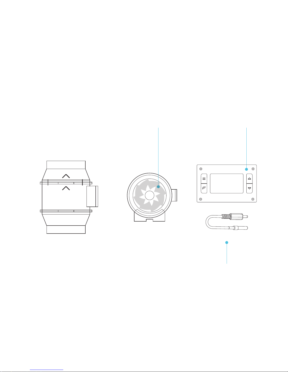
ACIFINITY AI-CLT4 User manual


Thank you for choosing AC Infinity. We are committed to product quality and
friendly customer service. If you have any questions or suggestions, please
don’t hesitate to contact us. Visit www.acinfinity.com and click contact for our
contact information.
WELCOME
EMAIL
support@acinfinity.com
WEB
www.acinfinity.com
LOCATION
Los Angeles, CA
3

MANUAL CODE CL1610X1
4
UPC-A
854759004785
854759004792
PRODUCT
CLOUDLINE T4
CLOUDLINE T6
MODEL
AI-CLT4
AI-CLT6

5
MANUAL INDEX
Manual Index....................................................................
Key Features ...................................................................
Product Contents .............................................................
Installation ......................................................................
Powering and Setup ........................................................
Cleaning ..........................................................................
Controller Programming ..................................................
Other AC Infinity Products ..............................................
Warranty ..........................................................................
Page 5
Page 6
Page 7
Page 9
Page 14
Page 17
Page 19
Page 25
Page 26

6
KEY FEATURES
QUIET PWM MOTOR
PWM-controlled motor features
precise speed control, reduced
rotor noise, and energy
efficient DC voltage.
IP 44 PROTECTION
Fans are IP44 rated; is
highly resistant to liquids
and dust; able to withstand
hot and humid environments.
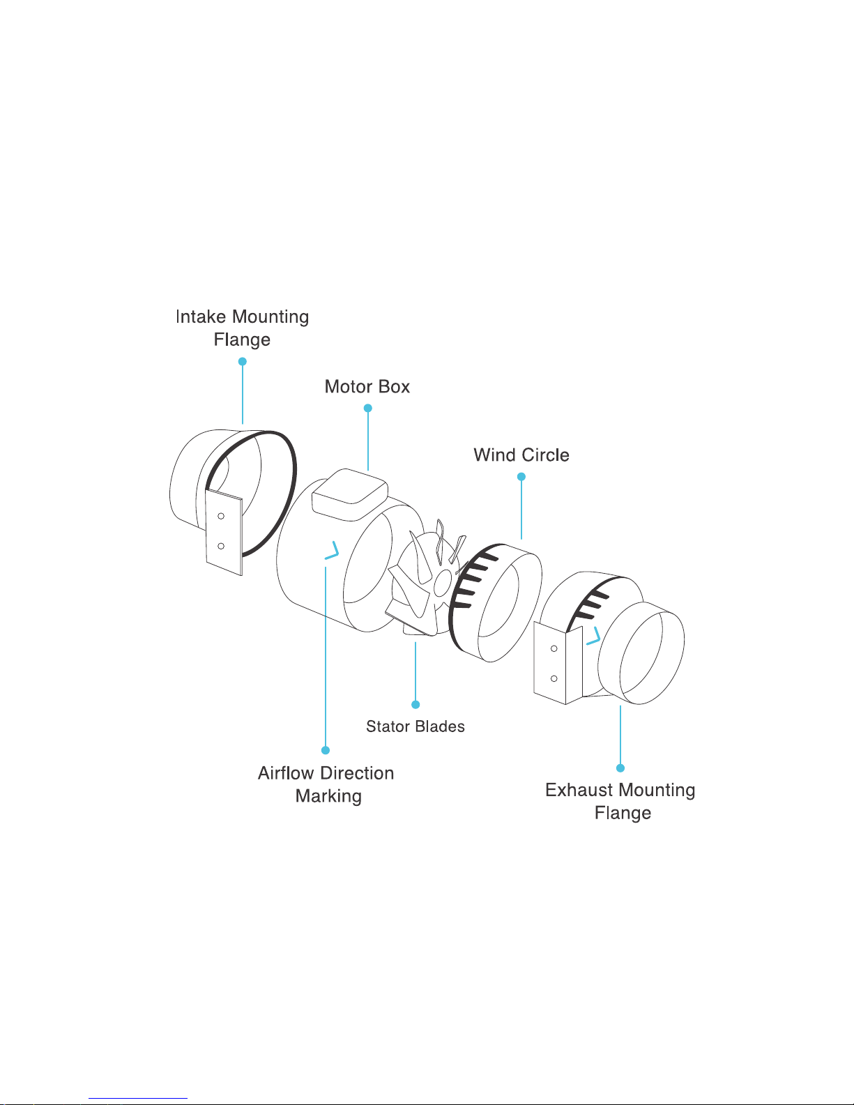
STATOR BLADE DESIGN
Hydro mechanical stator
blades enables air flow to
travel farther even in high
static pressure environments.
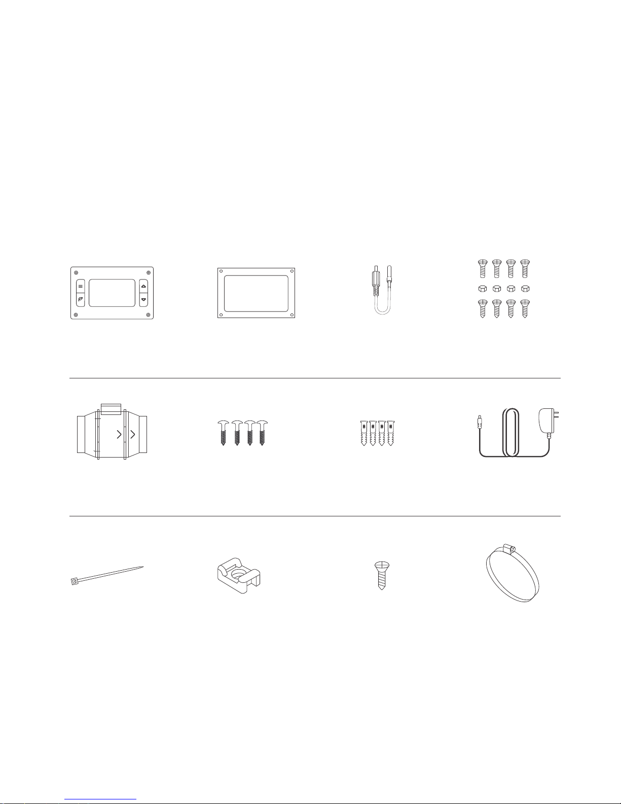
SMART CONTROLLER
LCD display enables temp
monitoring, thermal control,
speed control, alarms, and
SMART energy mode.
THERMAL PROBE
The corded sensor probe con-
structed of stainless steel en-
sures an accurate temperature
reading.
DUAL BALL BEARINGS
Motor contains ball bearings
rated at 67,000 hours. Also
enable the duct fan to be
mounted in any direction.
AC INFINITY

7
PRODUCT CONTENTS
CLOUDLINE T4
CLOUDLINE T6
AI-CLT4
AI-CLT6
AC INFINITY
THERMAL
CONTROLLER (x1)
THERMAL
PROBE (x1)
CONTROLLER PLASTIC
STENCIL (x1)
CONTROLLER
SCREW SET (x4)
WOOD SCREW
(x6)
DUCT TUBE
CLAMPS (x2)
DUCT FAN
SYSTEM (x1)
POWER
ADAPTER (x1)
DUCT FAN
SCREW SET (x4)
DUCT FAN
Wall Anchor (x4)
WIRE TIE
(x6)
CABLE TIE
MOUNT (x6)

8
PRODUCT CONTENTS

9
STEP 1
If your model has fixing clamps, use a
phillips screw driver and pliers to
unscrew the clamps. If your model
has built in plastic clamps, pull on
the buckle to release it.
STEP 2
After loosening the fixing clamps,
carefully remove the motor box from
the intake and exhaust mounting
flanges. Also remove the wind circle
found between the motor box and
intake flange.
INSTALLATION

10
INSTALLATION
STEP 3
Use the intake and exhaust mounting
flanges to position where you wish
the mount the duct fan. Use a pen or
pencil to mark the four mounting holes.
STEP 4
Double check to make sure the
location is structurally sound and free
from obstructions. Use a power drill
to drill the four mounting holes.

11
INSTALLATION
STEP 5
Insert the four wall anchors included
with this product in each of the drilled
mounting holes. You may need to use a
hammer to secure them through the
holes.
STEP 6
Position the mounting flanges and
align the mounting holes with the wall
anchors. Use a screw driver or drill to
secure the four wood screws through
the mounting frame and into the wall
anchors. Please make sure the airflow
direction marking is aligned with your
intended direction.

12
INSTALLATION
STEP 7
If your model has metal fixing
clamps, position them back onto
the input and exhaust flanges.
Also, remember to position the
wind circle back to the flange.
Do not tighten the screws yet.
STEP 8
Secure the motor box back onto
mounting flanges. Please make sure
the airflow direction marking on the
motor box matches the marking on
the exhaust flange.

13
INSTALLATION
STEP 9
If your model has metal clamps,
tighten the clamps using a phillips
screw driver and pliers. If your
model has plastic clamps, push
the buckle back down to tighten.
STEP 10
If using a duct tube, position it to
fully cover the hole of the exhaust
or intake flange. Secure the fan
included duct tube clamp over it
and tighten with a flathead screw
driver.

14
POWERING AND SETUP
STEP 1
The duct fan unit comes corded with
a 4-pin molex connector. Locate the
connector and plug it into the back
side of thermal controller under “FANS”.
STEP 2
Remember that cord length can be
organized using the tie mount, wood
screw, and wire tie included with your
product. You can secure the tie mount
onto a surface using the wood screw.
Then wrap the wire tie around the
powercord into the tie mount.
AC INFINITY

15
POWERING AND SETUP
STEP 3
Locate the connector plug of the
thermal probe and plug it into the
backside of the thermal controller
under “SENSOR”.
STEP 4
Secure the thermal probe head next
your electrontics, preferably near the
hottest device. You can use the wire
tie to secure the probe onto a rack rail
or the cable tie mount to a surface.
AC INFINITY

16
POWERING AND SETUP
STEP 5
Plug the DC connector of the power
adapter into the backside of the
thermal controller under “POWER”.
STEP 6
Lastly, plug the power adaper into an AC
power outlet. The adapter is rated at 100
to 240V AC 50/60 Hz and a plug adapter
can be attached to make it compatible to
various outlet types.
AC INFINITY

17
CLEANINGCLEANING
STEP 1
Remove the motor box from the mounting
flange. Please refer to steps 1 and 2 on
page 9 for more information on proper
motor box removal.
STEP 2
Use a damp cloth to clean the dust and dirt
off the impellar and fan blades. Remove the
wind circle that’s between the motor box and
input flange for cleaning.

18
CLEANINGCLEANING
STEP 3
Clean the dust and dirt off the stator
blades on the opposite side. Remember
to clean the area inside the output and
exhaust flanges.
STEP 4
Lastly, secure the motor box back onto the
mounting flanges. Please refer to steps
7 through 9 on page 12 and 13 for more
information on securing the motor box.

19
T-SERIES CONTROLLER
PROGRAMMING
1. MODE BUTTON
Cycles through the unit’s
modes: AUTO, SMART,
OFF, ON, ALARM. Hold
for three seconds will lock
or unlock the display.
2. UP / DOWN BUTTON
The up and down buttons
change the setting temp,
alarm temp, display
brightness, or the speed
of the fan.
3. LEAF BUTTON
This turns the display off
while allowing the
programs to run. Holding
will change degrees to
Fahrenheit or Celsius.
4. SETTING TEMP
Shows the temperature you
set the fans to trigger in
AUTO and SMART Mode.
5. ALARM TEMP
Shows the temperature
that you set the fan’s
alarm system to trigger.
6. PROBE TEMP
Actively shows current
temperature that the
probe is measuring.
7. FAN SPEED
Shows what speed the fans
are currently running at. Six
speeds are available.
8. BRIGHTNESS
Shows the brightness
of the display. Three
settings are available.
9. ALERT ICONS
Flashes to indicate if fan
failure, alarm, or display
lock is being triggered.
1
3
2
ALARM
SETTING
F
o
F
o
PROBE
F
o
4
5
6
7 8
9

20
T-SERIES CONTROLLER
PROGRAMMING
QUICK START
Press the MODE button until you are on AUTO mode. This mode works like a thermostat.
Press the up and down triangle buttons to change the SETTING temperature on the screen.
The PROBE temperature is what the thermal probe is measuring. When the PROBE
temperature exceeds the SETTING temperature, the fans will start running.
ON MODE
In this mode, the fans will run non-stop regardless
of temperature. Pressing the up and down buttons
while in this mode will change the speed of the fan.
Whichever speed is designated in this mode will
also be the speed used in AUTO Mode and the
max speed of the fans in SMART Mode.
AUTO MODE
This is the thermostat setting where the fans will
start running when the PROBE temperature
reaches or surpasses the SETTING temperature.
The SETTING temperature can be designated by
pressing the up and down buttons while in this
mode. Once the fans start running, the PROBE
temperature would need to fall at least 4° F below
the SETTING temp for the fans to stop running.
This variation buffer can be changed to 2° F.
See page 23 for more information.
ALARM
SETTING
F
o
F
o
PROBE
F
o
ALARM
SETTING
F
o
F
o
PROBE
F
o
This manual suits for next models
1
Table of contents