Ackutech slider L100 User manual

Ackutech AG · Lettenstrasse 6 · 6343 Rotkreuz · Schweiz
Tel +41 41 784 20 00 · Fax +41 41 784 20 09 · info@ackutech.ch · www.ackutech.ch
slider L100 – Montageanleitung
Flügelgewicht bis 100 kg
Mai 2014
Bitte lesen Sie diese Montageanleitung sorgfältig, bevor Sie mit der Montage
beginnen.
Wichtiger Hinweis zu Fräs- und Bohrbilder: Jeder slider-Beschlag erhält einen
eigenen Plan. Dieser kann sich von Objekt zu Objekt ändern, sofern nicht
ausdrücklich die gleiche Ausführung (Produktionsnummer gem. Auftrag) bestellt
wird. Es gelten nur die von uns mitgelieferten Pläne pro Auftrag.

16
Fasi preparatorie
1) Prima di assemblare la strut-
tura, fissare le clip sulla parte
superiore dei cieli (Fig. 1) e
sulla parte inferiore delle basi
(Fig. 2) con viti TPS.
Vorbereitungsphasen
Preparatory phases
1) Bevor der Korpus zusam-
mengebaut wird, die Clips
oben an den Oberseiten (Abb.
1) und unten an den Sockeln
(Abb. 2) mit Schrauben TPS
befestigen.
1) Before assembling the struc-
ture, attach the clips on the
upper parts of the tops (Fig.
1) and on the lower parts of
the bases (Fig. 2) using TPS
screw.
Fig. 1
Abb. 1
Fig. 2
Abb. 2

17
3) Misurare la luce interna tra i
fianchi laterali
X
(Fig. 3). Ac-
corciare, se necessario, le
coperture frontali (Fig. 4).
Meccanismo
di scorrimento
superiore
2) Mettere in bolla il contenito-
re.
Oberer
Gleitmechanismus
superiore
Upper sliding
mechanism
3) Den inneren Abstand zwi-
schen den Seitenwänden X
messen (Abb. 3). Die frontale
Abdeckung (Abb. 4).
3)
Measure the distance be-
tween the sides X(Fig.3). If
necessary, shorten the pro-
vided front cover (Fig. 4).
2) Den Korpus ins Lot bringen.
Fig. 3
Abb. 3
Fig. 4
Abb. 4
2) Ensure the cabinet is plumb
and level.
XX–1
2mm
Meccanismo
di scorrimento
superiore

18
Meccanismo
di scorrimento
superiore
4) Spostare un carrello nella
posizione di totale apertura
(Fig. 5 ) per poter agganciare
la copertura frontale (Fig. 6A,
6B e 6C). Ripetere l’opera-
zione sull’altro lato.
5) Importante! Posizionare la
copertura frontale sul mec-
canismo in modo che fuori-
esca lateralmente dello stes-
so valore A.
Oberer
Gleitmechanismus
Upper sliding
mechanism
4)
Einen Schlitten auf die Position
der totalen Öffnung schieben
(Abb. 5), damit die Frontab-
deckung eingehängt werden
kann (Abb. 6A, 6B und 6C).
An der anderen Seite auf glei-
che Weise vorgehen.
5) Important! Position the front
cover on the mechanism in
a way so that it comes out
of the side of the Avalue in
equal amounts.
5)
Wichtig! Die Frontabde-
ckung so am Mechanismus
positionieren, dass sie seit-
lich aus dem Wert
A
austritt.
Fig. 6A
Abb. 6A
Fig. 6B
Abb. 6B
Fig. 6C
Abb. 6C
_
.
_
.
_
.
_
.
_
.
_
.
_
Fig. 5
Abb. 5
4) Move a carriage into the to-
tally open position (Fig. 5)
in order to fasten the front
cover (Fig. 6A, 6B and 6C).
Repeat the operation on the
other side.
A A
_
.
_
.
_
.
_
.
_
.
_
.
_

19
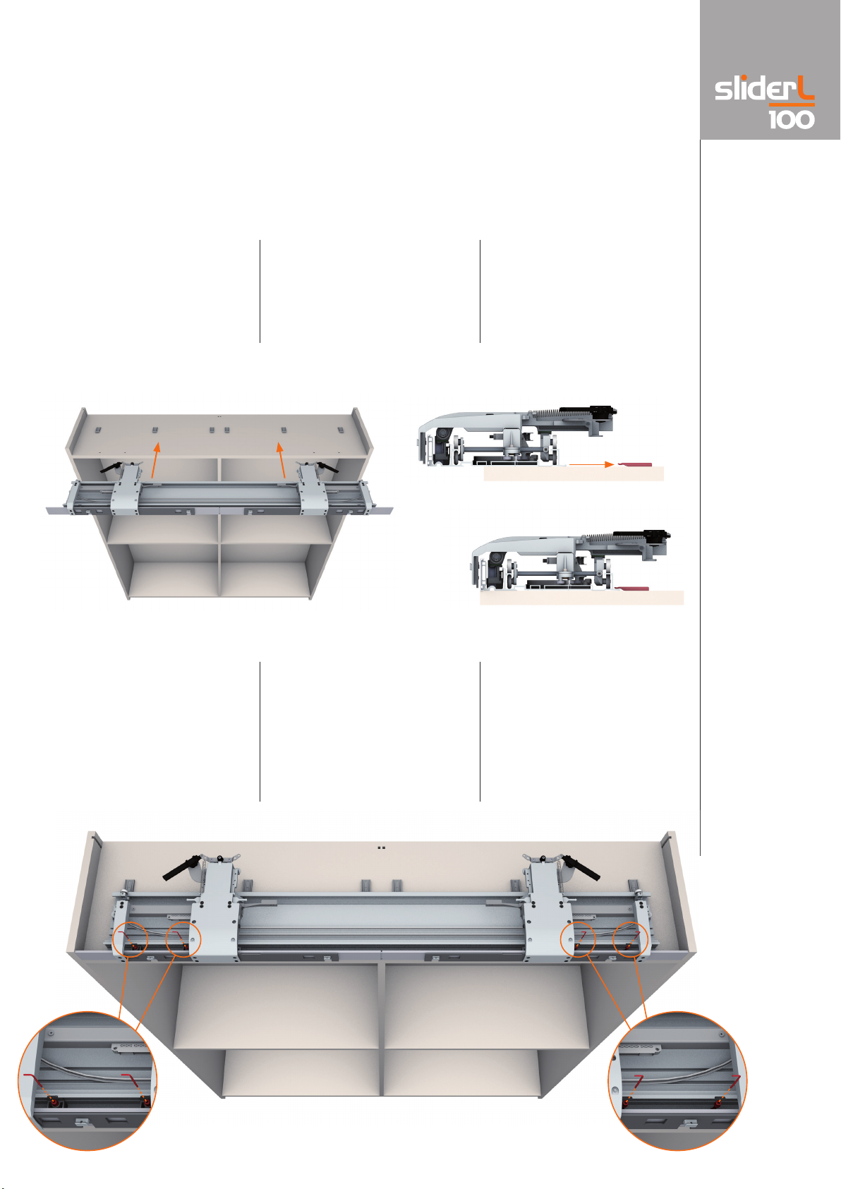
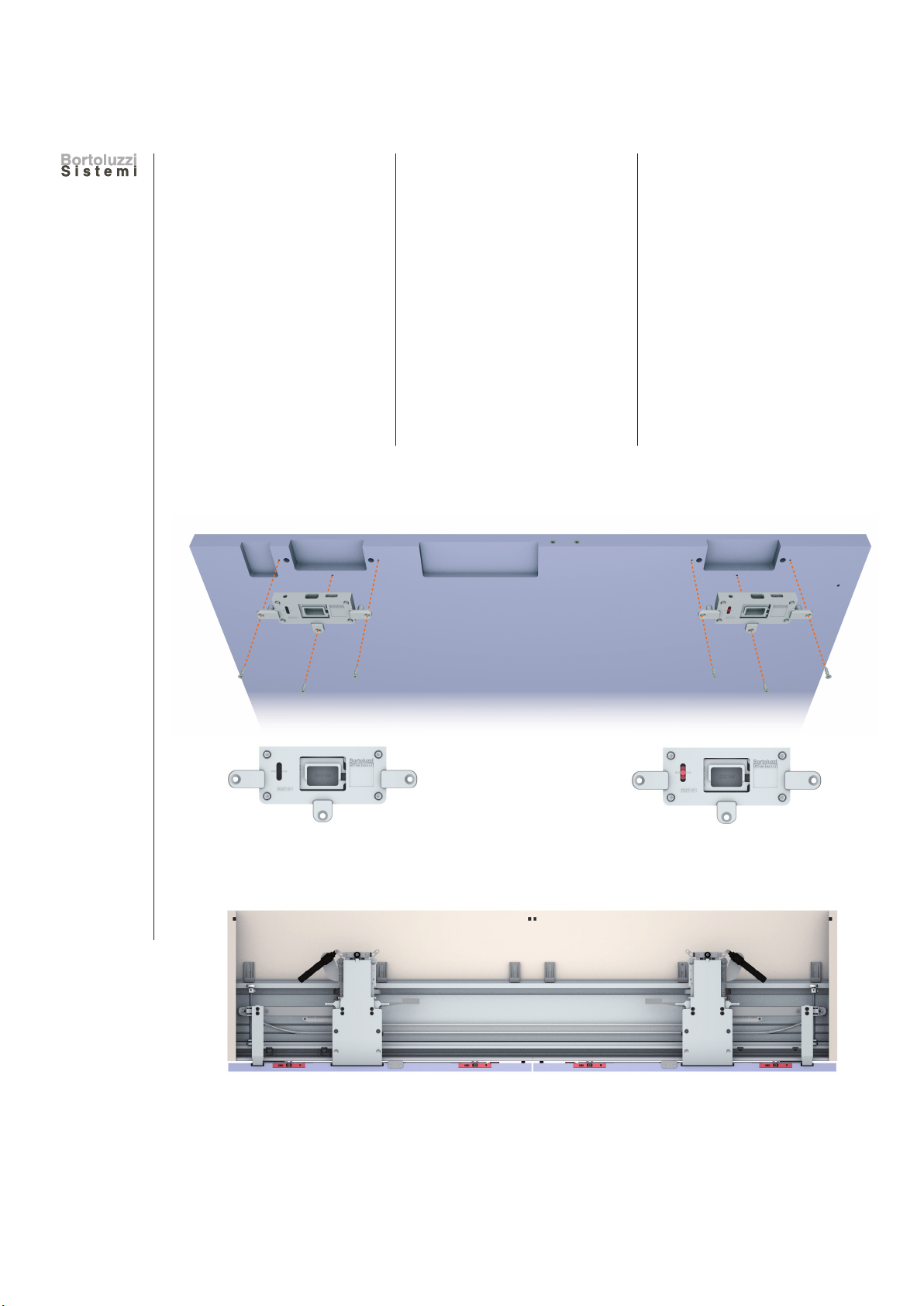
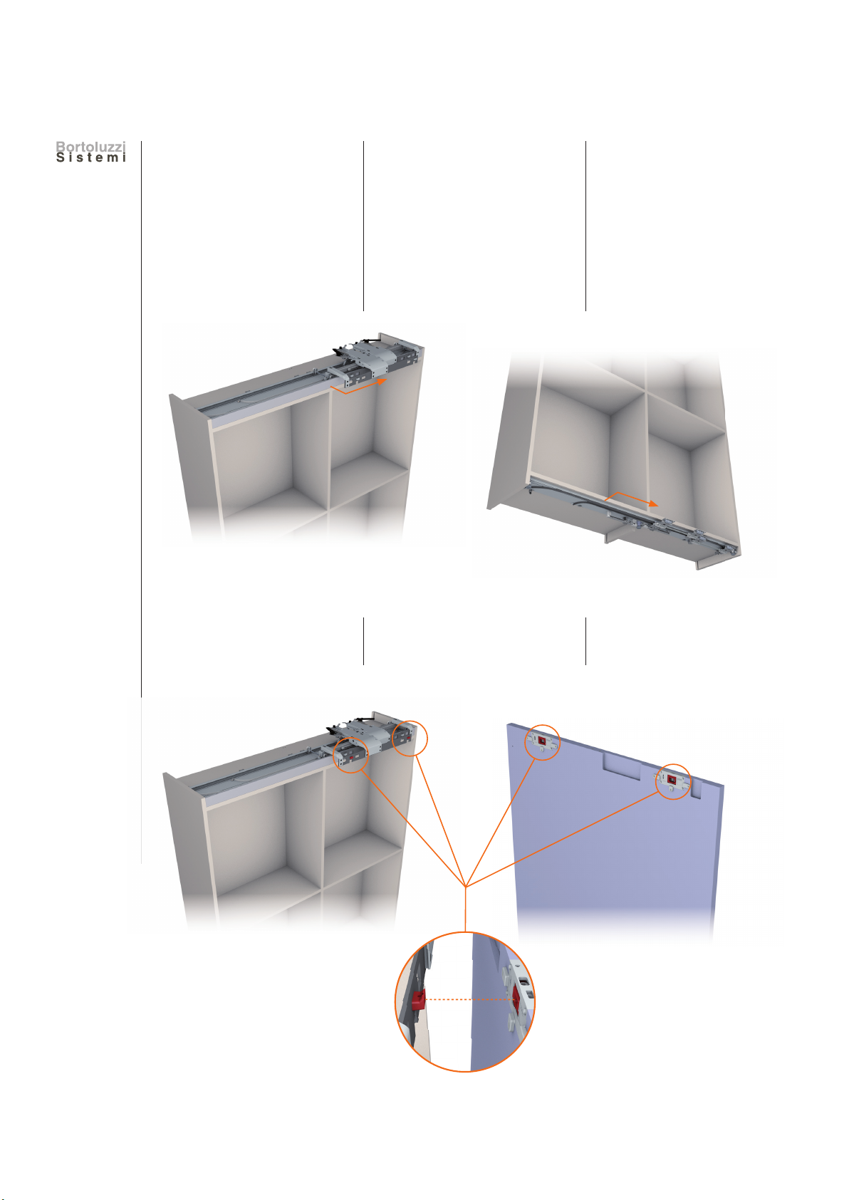
6) Applicare il meccanismo su-
periore sul cielo dell’armadio
(Fig. 7) facendo attenzione
che si agganci correttamen-
te alle clip (Fig. 8A e 8B).
7) Fissare il meccanismo al cie-
lo tramite le viti presenti alle
due estremità (2 o 4), inizian-
do dalla prima di sinistra che
garantirà la corretta posizio-
ne del sistema. Fissare poi le
altre viti presenti.
_
.
_
.
_
.
_
.
_
.
_
.
_
6) Apply the upper mechanism
on the top of the cabinet
(Fig. 7) making certain that it
fastens correctly to the clips
(Fig. 8A and 8B).
6) Den oberen Mechanismus
am Oberteil des Schranks
anbringen (Abb. 7), so dass
er korrekt an den Clips ein-
gehängt wird (Abb. 8A und
Abb. 8B).
7) Fasten the mechanism to
the top using the screws lo-
cated on the two ends (2 or
4), starting from the first on
the left, which ensures cor-
rect positioning of the sys-
tem. Then fasten the other
screws.
7) Den Mechanismus mit den
Schrauben an den beiden
Enden
(2 oder 4)
am Oberteil
befestigen, dabei mit der ers-
ten links beginnen, welche die
korrekte Position des Systems
gewährleistet. Anschließend die
übrigen Schrauben einsetzen.
Fig. 7
Abb. 7
Fig. 8A
Abb. 8A
Fig. 8B
Abb. 8B

20
Meccanismo
di scorrimento
inferiore
Nel caso di meccanismo su
misura, passare al punto 9.
8) Preparare il meccanismo infe-
riore estraendo in egual misu-
ra (A) i piedini laterali fino ad
ottenere la larghezza X–1.
9) Applicare il meccanismo infe-
riore sotto il basamento (Fig.
9), facendo attenzione che si
agganci alle clip (Fig. 10).
Unterer
Gleitmechanismus
Lower sliding
mechanism
In the case of custom mecha-
nism go on point 9.
8) Prepare the lower mechanism
by extracting the side support
feet in equal amounts (A) until
obtaining the width X–1.
Bei kundenspezifischen Maßen
des Systems gehe weiter zu
Punkt 9.
8) Den unteren Mechanismus
vorbereiten, indem die seitli-
chen Füße in gleichem Maß
(A) ausgezogen werden, so
dass die Breite X–1 erhalten
wird.
9) Apply the lower mechanism
under the base (Fig. 9), mak-
ing certain that it fastens to
the previously attached clips
(Fig. 10).
9) Den unteren Mechanismus
unterhalb des Unterbaus
(Abb. 9) anbringen, so dass
er an den Clips eingehängt
wird (Abb. 10).
Fig. 9
Abb. 9
Fig. 10
Abb. 10
X–1
_
.
_
.
_
.
_
.
_
.
_
.
_
_
.
_
.
_
.
_
.
_
A
A

21
10) Bloccare il meccanismo sui
fianchi del mobile tramite le
viti presenti su entrambi i
piedini laterali.
11) Importante! Bloccare il bi-
nario facendo scendere i
piedini laterali e centrali (Fig.
11 e 12) mettendoli in pres-
sione. Inserire carter copri-
piede (Fig. 13).
10
) Fix the mechanism onto the
sides of the furniture unit with
the screws located on each of
the side support feet.
10) Den Mechanismus mit den
Schrauben der beiden Sei-
tenfüße an den Möbelsei-
ten blockieren.
11) Important! Fix the bottom
track in position by extend-
ing all the feet (Fig. 11 and
12). To insert cover foot (Fig.
13).
11) Wichtig! Das Profil arretie-
ren indem man die seitlichen
und mittleren Füße nach un-
ten dreht bis (Abb. 11 und
12 diese unter Druck ste-
hen. Blende Stellfuß einfün-
gen (Abb. 13).
Fig. 11
Abb. 11
Fig. 12
Abb. 12
Fig. 13
Abb. 13

22
Fig. 14
Abb. 14
Fig. 15
Abb. 15
B B
B A
A A
Preparazione
dell'anta
12) Fissare i regolatori superiori
(Fig. 14), verificandone la
corretta disposizione come
illustrato dalle immagini
(Fig. 15).
A= Regolatore
verticale e orizzontale.
B= Regolatore
verticale.
Vorbereitung
des Flügels
Door preparation
12) Fix the upper regulators
(Fig. 14), checking the cor-
rect arrangement as illus-
trated in the images (Fig.
15).
A= Vertical and horizontal
regulator.
B= Vertical regulator.
12) Die oberen Regler befesti-
gen (Abb. 14), und die kor-
rekte Anordnung wie im Bild
gezeigt prüfen (Abb. 15).
A= Waagrecht-senkrecht
Ausrichtungs-
beschlag.
B= Senkrecht
Ausrichtungsbeschlag.

23
13) Inserire le bussole M6x23
nel bordo inferiore dell’anta.
Preavvitare le viti M6x22.
13) Insert the M6x23 bushings
in the lower edge of the
door. Begin to screw in the
M6x22 screws.
13) Die Buchsen M6x23 in die
untere Türkante einfügen.
Die Schrauben M6x22 vor-
schrauben.
10 mm
14) Applicare i paracolpi neri (in
dotazione).
14) Apply the black decelerat-
ing components (provided).
14) Die schwarzen Puffer an-
bringen (mitgeliefert).

24
Montaggio
delle ante
sul meccanismo
15) Spostare i carrelli superiore
ed inferiore dell’anta sini-
stra in posizione di totale
apertura.
16) Agganciare l’anta sinistra
alle mensole sporgenti dal
carrello superiore.
Montage
der Türflügel
am Mechanismus
Assembly of the
doors onto the
mechanism
15) Move the upper and lower
carriages of the left door in
the open position.
15)
Den oberen und unteren
Schlitten des linken Flügels auf
die offene Position bringen.
16) Fasten the left door onto
the supports on the upper
carriage.
16) Die linke Front an die Aufnah-
me des oberen Wagens ein-
hängen.

25
17) Important! Fix the door us-
ing the screws TCEI M5x16
(provided).
17) Wichtig! Den Flügel mit
den Schrauben TCEI
M5x16 blockieren (mitge-
liefert).
17) Importante! Bloccare l’an-
ta con le viti TCEI M5x16 (in
dotazione).
18) Fasten the upper angle
using the screws TPSEI
M4x12 (provided).
18) Den oberen Winkel mit
Schrauben TPSEI M4x12
(mitgeliefert) befestigen.
18) Fissare l’angolare superio-
re con viti TPSEI M4x12 (in
dotazione).

26
20) Chiudere le viti. 20) Tighten the screws. 20) Die Schrauben fest anzie-
hen.
21) Chiudere l’anta e ripetere le
operazioni dal punto 15 al
punto 19 per l’anta destra.
21) Close the door and repeat
steps 15 to 19 for the right
door.
21) Den Türflügel schließen und
für den rechten Türflügel
die Vorgänge von Punkt 15
bis Punkt 19 wiederholen.
Assembly of the
doors onto the
mechanism
Montage
der Türflügel
am Mechanismus
Montaggio
delle ante
sul meccanismo
19) Agganciare l’anta al carrel-
lo inferiore tramite le viti a
testa esagonale premonta-
te (vedi pag. 23).
19) Attach the door to the
lower carriage using the
pre-mounted hexagonal
screws (see page 23).
19) Den Türflügel mittels der
vormontierten Sechs-
kantschrauben am unteren
Laufschlitten einhängen
(siehe S. 23).

27
Regolazioni
22) Aprire completamente l’an-
ta di sinistra.
23) Livellare l’anta agendo su
entrambi i regolatori supe-
riori A e B. Ripetere l’ope-
razione per l’anta destra.
Adjustments Regulierung
22) Completely open the left
door.
22) Den linken Flügel ganz
öffnen.
23) Level the door using the
upper regulators A and B.
Repeat the operation on
the right door.
23) Den Flügel durch Einwir-
ken auf die beiden Regler
A und B nivellieren. Für den
rechten Flügel die Schritte
wiederholen.
Una corretta regolazione del-
le ante ne garantirà, in fase di
apertura, l’arresto simultaneo
sia nella parte superiore che in-
feriore del meccanismo.
Correct adjustment of the
doors will ensure simultaneous
stopping in both the upper and
lower parts of the mechanism
during the opening phase.
Die korrekte Einstellung der
Flügel sichert den gleichzeiti-
gen Anschlag am oberen und
unteren Teil des Mechanismus
beim Öffnen.

28
5 mm
7 mm
Regolazioni
24) Con ante chiuse, regolare
lo spazio centrale (minimo
5 mm) agendo sui regola-
tori superiori di tipo A.
25) Regolare la distanza fra le ante
e la struttura (circa 7 mm).
ASulla parte superiore, agi-
re sul grano M8 presente
lateralmente in ogni carrello
(Fig. 16).
24) Bei geschlossenen Flügeln
den mittleren Abstand re-
gulieren (mindestens 5
mm), indem auf die beiden
oberen Regler Typ A einge-
wirkt wird.
24) With the doors closed, ad-
just the central space (at
least 5 mm) using the type
A upper regulators.
Adjustments Regulierung
25) Adjust the distance be-
tween the doors and the
structure (approximately 7
mm) of each carriage.
AOn the upper part, use the
grub screws present on the
lateral one (Fig. 16).
25) Den Abstand zwischen den
Flügeln und dem Korpus
regulieren (ca.7 mm).
AAm oberen Teil über die
Einstellschraube M8 alle
Schlitten justieren (Abb.
16).
Fig. 16
Abb. 16

29
BSulla parte inferiore, agire
sulla vite M5 presente in
ogni carrello laterale.
BAt the bottom, tighten the
M5 screw on the side car-
riage.
BAm unteren Teil mittels der
Einstellschraube M5 alle ex-
terne Laufschlitten justieren.
7 mm

30
Regolazioni Adjustments Reguliering
26) Verificare la chiusura delle
ante. Se troppo lenta, au-
mentare la forza della molla
togliendo l’anello alla sua
estremità.
27) Applicare i due carter co-
pricarrelli (optional).
26) Das Schließen der Flügel
kontrollieren. Erfolgt es zu
langsam, die Federkraft er-
höhen, indem der Ring am
Federende entfernt wird.
27) Die beiden Blende für Lauf-
wagen anbringen (optional).
26) Check closure of the doors.
If too slow, increase the
force of the spring by re-
moving a ring from its end.
27) Apply the two plastic cov-
ers (optional).

31
Probleme
und Lösungen
TroubleshottingProblemi
e soluzioni
A) Angolo anta in basso
che sporge.
The bottom edge of the
door does not sit flush.
Die Türkante unten ragt
hervor.
A1) Il mobile non è ortogonale,
regolare il mobile.
The cabinet is distorted,
adjust the cabinet accord-
ingly.
Der Schrank ist nicht or-
thogonal, bitte richten Sie
den Schrank aus.

32
Problemi
e soluzioni
Troubleshotting Probleme
und Lösungen
B1) Controllare la messa in
bolla dell'anta che va ese-
guita ad anta aperta.
With the door in the open
position check that it is
level.
Die Tür in geöffneter Posi-
tion ausrichten.
B2) Il cielo cala sotto il peso
dell'anta, inserire un mon-
tante.
The upper horizontal cabi-
net section bows under
excessive weight, insert
supplementary partition to
support the load.
Der Oberboden biegt
durch unter dem Gewicht
der Tür. Bitte verstärken
Sie den Boden oder stellen
eine zusätzlich Mittelseite.
B) L'anta da aperta non è
verticale.
The door in the open
position is not aligned
vertically.
Die Tür in der offenen
Position ist nicht senk-
recht.

33
B3) Controllare le corrette di-
stanze tra le fresature.
Check the distances are
correct between cabinet
workings as per specified
drawings.
Überprüfen Sie die kor-
rekten Abstände zwischen
den Frästaschen.
B4) Controllare, per i prodotti
standard, che i due binari
siano centrati rispetto al
mobile.
For standard products,
check that the two tracks
are centered on the cabi-
net.
Bei Standardlängen über-
prüfen Sie bitte, ob bei
beiden Schienen der Ab-
stand zu den Seiten gleich
ist.
X
Y
Y
X
?
? ? ? ? ?
? ?

34
Problemi
e soluzioni
Troubleshotting Probleme
und Lösungen
C) L'anta non si chiude da
sola, bisogna forzare.
The door does not close
by itself, you have to
force it.
Die Tür schließt nicht
von selbst, sondern Sie
müssen sie beschleuni-
gen.
C1) Ricontrollare le lavorazioni
o la posizione dei supporti
sulla parte superiore e in-
feriore dell'anta.
Re-check the cabinet
workings. In addition
check the position of the
adjusters at the top and
bottom of the door.
Erneute Überprüfung der
korrekten Abstände zwi-
schen den Frästaschen,
bzw. der Verstellbeschlä-
ge auf dem oberen und
unteren Rand der Tür.
C2) Il mobile è fuori diagonale.
The cabinet is skewed/
twisted may need to be
correctly aligned.
Der Schrank ist nicht senk-
recht. Bitte exakt ausrich-
ten.
90°
90°
90°
90°
?
? ? ? ? ?
? ?
Table of contents
Other Ackutech Indoor Furnishing manuals
Popular Indoor Furnishing manuals by other brands

Ameriwood HOME
Ameriwood HOME 9652301EBL manual

Coaster
Coaster 110293 Assembly instructions

FMD Furniture
FMD Furniture Azur 662-001 Assembly instruction

DREAMS
DREAMS 820-00758 quick start guide

CLEAR DESIGN
CLEAR DESIGN BLLBFV2 Assembly instructions

Synargy
Synargy OUTER SPACES HELSINKI 3 PCE CHAT SET Assembly instructions

Furn Mill
Furn Mill HOBED00122 Assembly instruction

Cypress Hills
Cypress Hills AXCRGREY15 Assembly instructions

LEMI
LEMI SOSUL Series Original instructions

Next
Next WHITE GLOSS TV UNIT 997632 Assembly instructions

Bandits and Angels
Bandits and Angels Little Lady Assembly instructions

BEMMA
BEMMA GRACIE V-GR24SFM manual