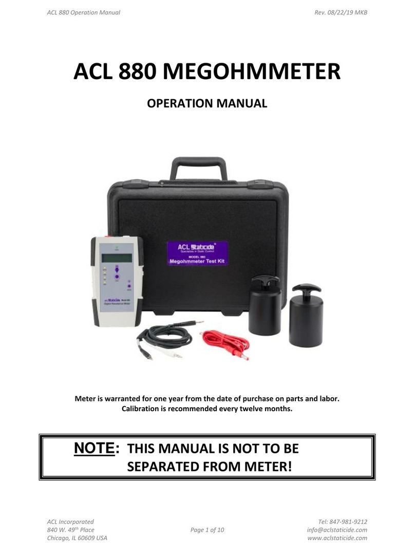
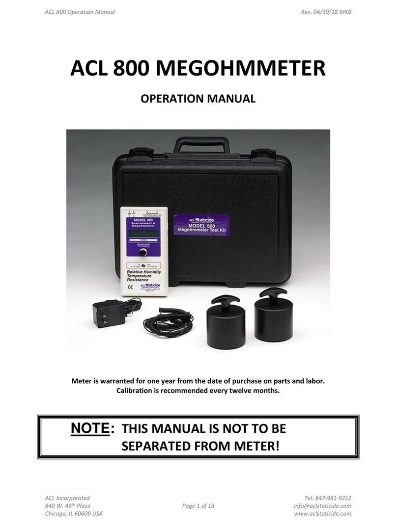
ACL 800 User manual

ACL 800 MEGOHMMETER
OPERATION MANUAL
Meter is warranted for one year from the date of purchase on parts and labor.
Calibration is recommended every twelve months.
ACL Inc. Tel: 847-981-9212
Chicago, IL 60609 USA www.aclstaticide.com


ESD CHECK ACL 880 DIGITAL RESISTANCE METER
Secon Topic Page
I. Introducon & Descripon 4
II. Baery Installaon 6
III. Resistance Measurements in Automac Mode 8
IV. Electrificaon Period in AUTO/GO A Mode 9
V. Measurements in Manual Mode 10
VI. Baery Replacement 10
VII. User Adjustments & Maintenance 11
IX. Warranty Informaon 11
General Specificaons 13
Table of Contents
Copyright © 2019. All rights reserved. Printed in the United States of America. No part of this manual may be used
or reproduced in any manner whatsoever without wrien permission.

4Rev. B / June 2019
ACL 880 Digital Resistance Meter
I. Introducon & Descripon
The ACL 880 instrument is a digital resistance meter that measures accurately from 1.0x10³to 1.0x10¹²
ohms. In its AUTO mode the instrument automacally adjusts resistance range and selects test voltage
in accordance with standard pracces outlined in ANSI/ESD STM11.11, and meets audit requirements
of ESD TR53:
• <10 Volts Variable are applied from 1.0x10³ to 9.9x10³ohms and provides audible connuity indi-
caon below 1.6 ohms
• 10 Volts ± <0.5V (±<5% Constant Voltage, i.e., Under Load) applied from 1.0x10⁴to 9.99x10⁵ohms
• 100 Volts ± <5V (±<5% Constant Voltage, i.e., Under Load) applied from 1.0x10⁶to 1.0x10¹² ohms
A. Modes of Operaon
GREEN HOLD LED
ON WHEN HOLDING
MEASUREMENT IN
DISPLAY
GREEN TEST PAD
STARTS MEASURE-
MENT & USED FOR
OPERATION MODE
SELECTION
MAIN POWER
SLIDE SWITCH
ON/OFF
LIQUID CRYSTAL DISPLAY
(LCD) DISPLAYS & HOLDS
DATA FOR 10 SECONDS
YELLOW MODE PAD
OVERRIDES HOLD, PRO-
VIDES VOLTAGE SELEC-
TION AND CHANGES
INSTRUMENT OPERATION
BETWEEN AUTO AND
CONTINIOUS MODES
RED POSITIVE (+)
TEST VOLTAGE
BLACK NEGATIVE (-)
CURRENT SENSING
WHITE SHIELDING
CONNECTION

5
Rev. B / June 2019
ACL 880 Digital Resistance Meter
There are two main Modes of ACL 880 Operaon
1. AUTO mode (Displayed as GO A): Automacally adjusts resistance range, test voltage and Elec-
trificaon Period (EP). Measurements stops at the end of EP, Green LED is ON, measurement is
displayed for 10 seconds then instrument resets for the next measurement.
2. CONTINUOUS mode (Displayed
as GO C): Funcons as in AUTO mode by auto-
macally adjusng resistance range and test volt-
age, but connues to measure unl the operator presses
MODE, or restarts the measurement by pressing TEST.
GO C disables electrificaon period control.
3. Manual Voltage Selecon can be made in either AUTO or
CONTINUOUS modes by pressing the MODE pad before
starng the measurement.
a. To change the mode of operaon simultaneously press
and release the TEST and MODE pads.
Figure 2: ACL 880 in AUTO -
Default Operaon Mode
Figure 3: ACL 880 in Connuous
Op-eraon Mode
Figure 4: Press MODE to manually
Change Test Voltage

6Rev. B / June 2019
ACL 880 Digital Resistance Meter
II. Baery Installaon
• Baery Main Power OFF
• Open Baery Cover
• Replace Baery (9V Alkaline)
• Close Cover
A. Install test leads or special fixtures as shown:
1. Slide MAIN POWER Switch to ON
2. “Go A” is the Default Operaon Mode and is displayed when
MAIN POWER is ON
3. To Start Measurement use the Green TEST Pad
a. Press & release TEST Pad
b. Measurement sequence is conducted automacally; ends
when Green HOLD LED is ON
c. Press MODE to interrupt or clear measurement
4. Data is displayed in the LCD & Hold Indicator LED [Top Panel]
glows green. Press the Yellow MODE buon once to erase the
data.
NOTE: Press TEST to restart the measurement at any me
B. The MODE buon performs four useful funcons:
Figure 5: Main Power Baery Cut-OffSwitch
on side of Instrument
Figure 6: ACL 880 Baery
Compart-ment on boom of
Instrument
Baery Cover
Philips #1 screw
Figure 7: Test Lead Connecons:
White = Shield
Black = Current Sensing
Red = Test Voltage

7
Rev. B / June 2019
ACL 880 Digital Resistance Meter
1. Override Displayed Data Hold: Resets the instrument for the next measurement and bypasses
the automac HOLD funcon. Note that the exisng measurement in the display is discarded.
2. Used with TEST pad to change modes of operaon between AUTO / GO A & CONTINUOUS /
GO C operaon
3. Selects funcon and starng test voltage for AUTO, or CONTINUOUS mode
4. Iniates CAL? funcon:
a. CAL? Funcon: Is used by qualified ACL Staticide® trained technicians to adjust
instrument test voltages using a special technique to maintain specificaon
performance. Do not try to adjust test voltages. Exit out of CAL?
5. Mode Sequence For manual selecon of test voltage:
a. First Press: Manual <10 Volt Test Voltage
b. Second Press: Manual 10 Volt Constant Test Voltage
c. Third Press: Manual 100 Volt Constant Test Voltage
d. Fourth Press: Return to AUTO mode operaon
1. Be aware that other leads may not provide similar performance and will require recalibraon
of the Null point to improve measurement accuracy.
C. Connecons
Leads are connected to the Posive (+) and Negave (-) receptacles for
resistance instrument measurements. The black sensing lead incorpo-
rates shielding; the shield is connected to the instrument via the white
banana plug and receptacle, as shown in Figure 7.
Receptacles are separated by ¾ inch spacing (see Figure 10) to accom-
modate dual banana plug connectors. These connectors are used for
microprobes resistance measurement fixtures.
Leads supplied with the ACL 880 are specially designed for this
instrument. They have superior outer insulaon and a high number of
stranded con-ductors to minimize measurement errors.
2. Always use supplied leads for best performance.
a. Lead quality and length affect instrument accuracy. This is due to several factors such as
insulaon resistance, lead inductance and capacitance, as well as transmied “noise” in the
environment. To minimize the effect of noise and transmied energy on measurement ac-
curacy, the black sensing lead is shielded.
b. Long 200 cm leads are supplied for auding purposes where lead length is physically neces-
sary. Long leads will allow the instrument to perform within its targeted performance.
Figure 8: Mode Sequnce

8Rev. B / June 2019
ACL 880 Digital Resistance Meter
Figure 9: The shield is connected to the me-
ter via the white banana plug and receptacle
Figure 10: Receptacle spacing accommodates
dual banana plug connectors.
III. Resistance Measurements in Automac Mode
In the default AUTO mode the instrument makes range and test voltage adjustments automacally,
depending on the resistance of the material or object being measured, and in accordance with stan-
dard measurement protocol.
A. Once leads are installed, slide the Main Power switch to ON.
B. Note that a yellow LED above AUTO lights to indicate the instrument is in automac mode.
C. With leads installed press and release the TEST pad. The measurement sequence will be conduct-
ed automacally unl either the Green LED illuminates, or
a. The test is interrupted by pressing the MODE buon once, or
b. The TEST buon is pressed to restart the measurement sequence.
Figure 11: Automac Mode

9
Rev. B / June 2019
ACL 880 Digital Resistance Meter
CAUTION
Test Voltage is supplied through the Red Posive (+) terminal. To measure in accordance
with industry standard protocol Test Voltage is applied during the measurement starng
at <10 volts (variable), and then automacally increased to constant 10 volts, or constant
100 volts as necessary. When applied, Test voltage magnitude is indicated on the front
panel by the illuminated yellow LED above the applicable voltage.
D. Record your measurement as may be required.
NOTE: Measurements will be erased and the instrument reset to zero for the next measurement
aer 10 seconds.
The ACL 880 measurement process is quite fast and once a measurement is stable in the LCD, the
operator may elect to use the stable displayed measurement. In this case the EP is manually
determined by the operator. This is an efficient operating procedure for determining if the
measurement is generally within the required range for the object being audited. In this case, the
operator usually observes and confirms measurement stability, which results in faster audit
measurements. However, if the measurement is of a crical nature , or being used for material
qualificaon purposes, the full EP for that measurement should be employed, i.e., when the
measurement is completed and displayed, and the Green LED comes ON as described below.
If the operator desires the EP to be determined by the instrument in AUTO/GO A mode, the Green
Hold LED illuminates when the appropriate measurement period for each measurement is reached.
It takes into account the material variables seen during the measurement and adjusts the EP for
opmal measurement accuracy. Typical EP’s for the ACL 880 instrument are:
1.0E3 to 1.0E9 ohms: Typically 2 to 8 seconds (Range Average 6.0 seconds)
1.0E09 to 1.0E11 ohms: 7 to 10 seconds
>1.0E11 to 1.0E12 ohms: 10 to 25 seconds
These values are variable and based on the stability of the materials being measured, as well as the
envi-ronmental condions. For example, while the default EP for the ACL 880 instrument is 7.5
seconds, EP auto-macally adjusts to enhance measurement accuracy.
IV. Electrification Period in AUTO/GO A Mode
Electrification Period (EP) is the me required for an instrument to make a measurement from zero
(0) within 5% of 1.0x10¹² ohms at 100 volts, plus 5 seconds. The EP is used for resistance measure-ments
equal to, or greater than 1.0x10⁶ohms. The 880 was designed to incorporate variable EP to allow fastest
possible, accurate measurements. Typical EP up to less than 1.0x10⁹ohms is typically less than 8.0
seconds. However, measurement condions in the factory environment vary considerably. To
compensate for variables in materials and condions, the 880 makes many measurements each second
and evaluates their consistency and stability. If necessary the 880 will automacally extend the
measurement me (EP) to insure an accurate representaon of the material under test.

10 Rev. B / June 2019
ACL 880 Digital Resistance Meter
V. Measurements in Manual Mode
To manually select a specific test voltage, once leads or fixtures are
installed, slide the Main Power switch to ON.
A. Press the MODE buon one me and note the illuminated LED
above AUTO is OFF, and the LED above <10V, is ON. This means the
test voltage is manually set to vary from approximately 1 mv to less
than 10 volts, depending on the resistance being measured.
B. Pressing the MODE buon a second me turns the LED adjacent to
<10V OFF, and the LED next to 10V ON. This indicates all measure-
ments will be made at a constant test voltage of 10 volts, which may
vary up to <0.5V depending on material resistance.
C. Pressing the MODE buon a third me moves illuminates the LED
above 100V, which provides a constant test voltage of 100V ± <2.0
Volts.
D. Press and release the TEST pad to make the measurement.
E. Record the measurement within 10 seconds following the illumina-
on of the Green HOLD LED.
F. Resistance measurement ranges in Manual mode are as follows.
@<10 Volts (Variable): 1.0E3 to 1.0E9 Ohms
@10 Volts (Constant): 1.0E4 to 1.0E10 Ohms
@100 Volts (Constant): 1.0E6 to 1.0E12 Ohms
VI. Baery Replacment
Before replacing the single 9V alkaline baery, slide the Main Power
switch to OFF. Open the baery compartment by removing the small
#1 Philips head screw. The baery is located in a small sealed compart-
ment. Carefully remove the baery and disconnect the terminal cap
from the baery.
DO NOT PULL THE WIRES TO RELEASE THE TERMINAL CONNECTOR!
CAREFULLY PRY THE TERMINAL CAP FROM THE BATTERY TO PREVENT
DAMAGE
Connect the new alkaline baery to the terminal and replace it in the
spring clamp; replace the baery cover. Use only alkaline baeries for
long life and to AVOID DAMAGE to the unit. Do not use standard car-
bon baeries as they:
• Will not last nearly as long as alkaline baeries
• May overheat causing instrument damage
• Will VOID the instrument’s warranty
Figure 12: Manual Mode
Figure 21: Baery Replace-
ment

11
Rev. B / June 2019
ACL 880 Digital Resistance Meter
VII. User Adjustments & Maintenance
The primary user adjustments are limited and have been previously described in this manual, i.e., the
Null adjustment to compensate for test lead resistance. There is no reason for the operator or unau-
thorized personnel to break the warranty seal and open the unit. The instrument’s circuits and me-
chanical connecons have been precisely installed and the instrument tested.
Annual calibraonincludesmeasurementoftestvoltageunderloadandaseriesoffunc onalresis-
tance test measurements. A qualifiedCalibra on Laboratory should make these measurements and
adjustments if necessary.
VIII. Warranty Informaon
A. Limited Warranty & Limitaon of Liability
Each ESD Check® product is warranted to be free from defects in material and workmanship under
normal use and service. The warranty period is one (1) year and begins on the date of shipment.
This warranty extends only to the original buyer or end-user customer and does not apply to fuses,
disposable baeriesortoanyproductwhich,inESDCheck’ s opinion, has been misused, altered,
neglected or damaged by accident or abnormal condionsofopera onorhandling.ESDCheck
warrants that soware will operate substanallyinaccordancewithitsfunc onalspeci ficaons
for 90 days and that it has been properly recorded on non-defecvemedia.ESDCheckdoesnot
war-rant that sowarewillbeerrorfreeoroperatewithoutinterrup on.
ESD Check reserves the right to invoice Buyer for importaon costs of repair/replacement parts
when product purchased in one country is submied for repair in another country.
ESD Check’s warranty obligaon is limited, at ESD Check’s opon, to refund of the purchase price,
free of charge repair, or replacement of a defecve product which is returned to ESD Check within
the warranty period. This warranty does not apply to roune calibraon of the instrument.
To obtain warranty service, contact ESD Check or send the product, with a descriponofthedif- fi
culty, postage and insurance prepaid (FOB Desna on),toESDCheck.ESDCheckassumesnorisk
for damage in transit. Following warranty repair, the product will be returned to Buyer, transpor-
taonprepaid(FOBDes na on). If ESD Check determines that the failure was caused by misuse,
alteraon,accidentorabnormalcondi onofopera o n or handling, ESD Check will provide an
esmate of repair costs and obtain authorizaon before commencing the work. Following repair,
the product will be returned to the Buyer transportaon prepaid and the Buyer will be billed for
the repair and return transportaon charges (FOB Shipping Point).
THIS WARRANTY IS BUYER’S SOLE AND EXCLUSIVE REMEDY AND IS IN LIEU OF ALL OTHER WAR-
RANTIES, EXPRESS OR IMPLIED, INCLUDING BUT NOT LIMITED TO ANY IMPLIED WARRANTY OF
MERCHANTABILITY OR FITNESS FOR A PARTICULAR PURPOSE. ACL Staticide SHALL NOT BE LIABLE
FOR ANY SPECIAL, INDIRECT, INCIDENTAL OR CONSEQUENTIAL DAMAGES OR LOSSES, INCLUDING
LOSS OF DATA, WHETHER ARISING FROM BREACH OF WARRANTY OR BASED ON CONTRACT, TORT,
RELI-ANCE OR ANY OTHER THEORY.
Out of Warranty Repairs
ACL Staticide expressly warrants that for a period of 90 Days from the date of repair, by ESD Check,
in-struments and products will be free of defects in material (parts) and workmanship (labor). If
ESD Check receives noce of such defect during the warranty period, ESD Check will replace or
repair at its expense such parts which it determines to be defecve. Any defecve part must be
returned

12 Rev. B / June 2019
ACL 880 Digital Resistance Meter
to ESD Check® postage prepaid with proof of purchase date. This warranty does not apply to rou-
ne calibraon of the instrument.
Warranty Exclusions - THE FOREGOING EXPRESS WARRANTY IS IN LIEU OF ALL OTHER WARRAN-
TIES, EXPRESS OR IMPLIED, INCLUDING BUT NOT LIMITED TO ANY IMPLIED WARRANTY OF MER-
CHANTABILITY OR FITNESS FOR A PARTICULAR PURPOSE. ACL Staticide SHALL NOT BE LIABLE FOR
ANY SPECIAL, INDIRECT, INCIDENTAL OR CONSEQUENTIAL DAMAGES OR LOSSES, INCLUDING LOSS
OF DATA, WHETHER ARISING FROM BREACH OF WARRANTY OR BASED ON CONTRACT, TORT, RELI-
ANCE OR ANY OTHER THEORY.
The express warranty does not apply to fuses, disposable baeries or to any product which, in ESD
Check’s opinion, has been misused, altered, neglected or damaged by accident or abnormal condi-
ons of operaon or handling.
Limit of Liability
In no event will ACL Staticide or any authorized reseller be responsible or liable for special,
incidental, or consequena l losses or damages, under any legal theory including but not limited
to contract, negligence, or strict liability. Fulfillment by ESD Check of its express warranty obliga
ons described above will be Buyer’s exclusive remedy and will be ESD Check’s and authorized
reseller’s limit of liability for any breach of warranty or otherwise.
Recommended Usage
ESD Check’s instruments and fixtures shall be operated at 65 – 90° Fahrenheit (18 – 32° Celsius),
10 – 60 % Relave Humidity. ESD Check recommends making measurements using its instruments
and fixtures in an environment of 72 – 76° Fahrenheit (22 – 24° Celsius), 25 – 35% Relave Humid-
ity.

13
Rev. B / June 2019
ACL 880 Digital Resistance Meter
ACL 880 Digital Resistance Specifica
ons CONTROLS
ON/OFF Baery Bus Cut-off
Slide Switch ON SIDE OF CASE
ON: Energizes instrument and LCD displays Soware Version then GO A with AUTO indicaon (Default)
OFF: Isolates baery and DC voltage from instrument controls and circuit. Use for transport and storage
TEST Pad
With Test Leads installed: Press once & Release. Measurements performed automacally.
In conjuncon with MODE changes from Auto operaon to Connuous.
MODE Pad
Steps through Auto/Voltage ranges with each press of MODE Pad:
• AUTO: Default automac resistance range & Voltage control
• <10V: Manual Operaon0.01to ≤10V Test Voltage;
- Resistance Range: 1.0E3 to 9.99E9 Ω
• 10V: Manual Operaon at 10V (Nominal, Semi-Constant)
- Resistance Range: 0.98E4 to 9.99E10 Ω
• 100V: Manual Operaon at 100V (±<5V) Constant Voltage
- Resistance Range: 0.98E6 to 1.0E12 Ω
- When data in HOLD, press MODE to terminate HOLD without changing operaonal
mode
- Press MODE with TEST to change from Auto to Connuous
- Used to measure lead resistance (NULL)
-Used by ACL Staticide Authorized Technicians for Voltage Calibraon
CONNECTIONS
Posive (+) Test Voltage (RED) – Supplies test voltage to electrodes/fixtures
Negave (-) Current sensing (BLACK) – Conducts current from electrode, fixtures or Ground to instrument
Chassis ( )Shielding connecon to chassis (WHITE) – Reduces transmied energy and effect on current
measurement.
Note: ¾ inch spacing between RED and BLACK accommodates dual banana BNC adapters
INDICATION Colored LED’s indicate instrument operaonal MODE and Test Voltage (YELLOW) used for the
current measurement, as well as measurement compleon (GREEN LED).
• AUTO: ON during automac operaons; OFF in Manual mode
• <10V:
• 10V
• 100V
• GREEN LED: Measurement hold

14 Rev. B / June 2019
ACL 880 Digital Resistance Meter
TYPICAL
TOLERANCES 1Nominal performance by range:
1.0E3 – 9.99E10 Ω<±2%, ±2 Counts
1.0E11 – 1.0E12 Ω<± 10%, ±4 Counts
TEST VOLTAGES Automacally selected and controlled in AUTO mode. May be manually selected
by pressing MODE pad in the following order:
• <10V Variable based on resistance load
- Provides 0.001 to ≤10V
- Funconal in AUTO within range 1.0E3 Ω- <1.0E+4 Ω
- Manual Operaon Resistance Range: 1.0E3 Ωto 9.99E+9 Ω
• 10V Constant Voltage (Under Load)
- Test Voltage Varies ± <5% in AUTO or Manual Operaons
- Funconal in AUTO within range 1.0E+4 Ω- <1.0E+6 Ω
-Manual Operaon Resistance Range: 0.9E+4 to 9.99E+10 Ω
• 100V Constant Voltage (Under Load)
- Test Voltage Varies ± <2% in AUTO or Manual Operaons
- Funconal in AUTO within range 1.0E+6 Ω- 1.0E+12 Ω
- Manual Operaon Resistance Range: 0.90E6 to 1.0E12 Ω
• Returns to Auto Mode
OPEN CIRCUIT
CURRENT <3mA @ 100V
MODES OF
OPERATION GO A: Performs all automac and manual voltage select funcons, stops and dis
plays measurements aer Electrificaon Period (EP) is complete, then displays data
with Green LED ON for 10 seconds.
GO C: Performs all automac and manual voltage select funcons, connuously
displays measurements unl the operator presses MODE or TEST pads. GO C
disables electrificaon period controls.
POWER One 9V alkaline transistor baery; baery life > 50 hours
DIMENSIONS 7.25 in. (184 mm) x 4.3 in, (109 mm) x 1.4 in. (36 mm)
WEIGHT 13.2 oz. (375 gram) with baery installed
NOTES 1Tolerance and accuracy measurements were conducted under controlled condions with
close tolerance reference resistors. Do not aempt to open instrument case.
• No internal operaonal parts or adjustments
• Provides access to 100DCV power supply
• Damage to instrument and environmental seals may occur
• Will void warranty
• Store instrument in case and dry environment

15
Rev. B / June 2019
ACL 880 Digital Resistance Meter
Other manuals for 800
2
Table of contents
Other ACL Measuring Instrument manuals