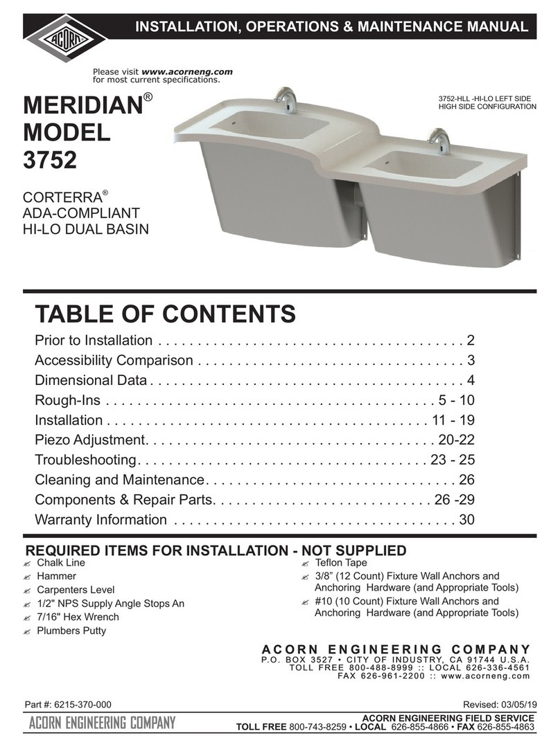
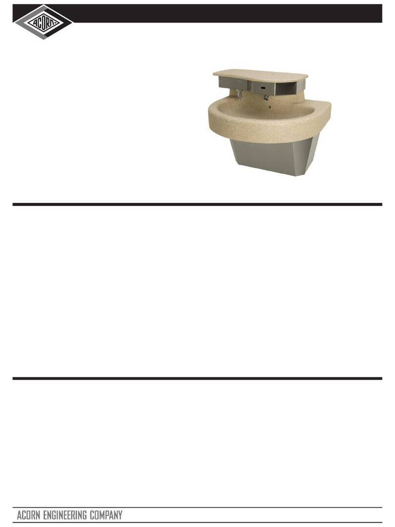
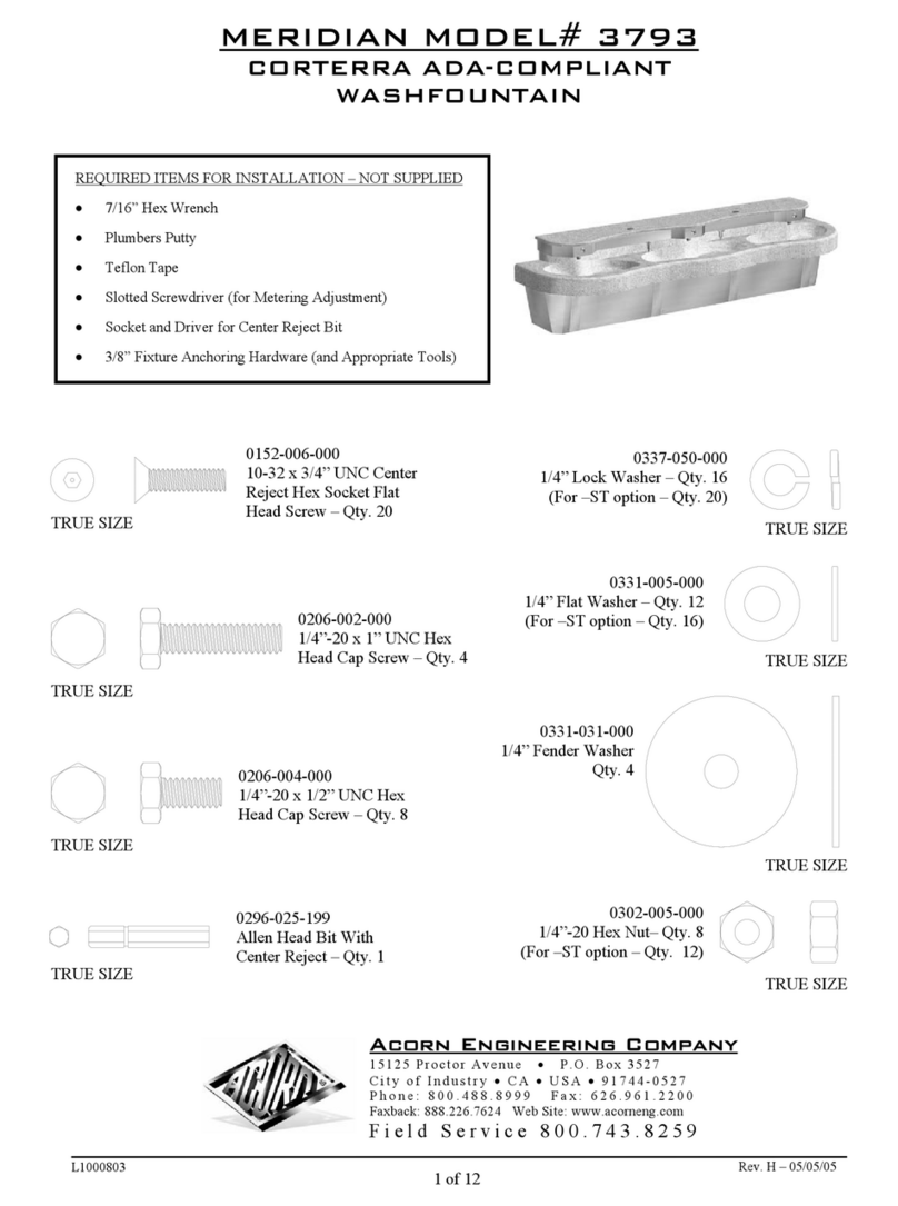
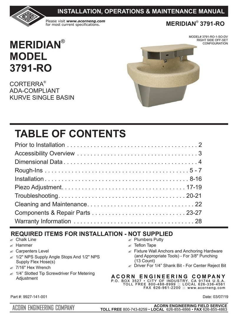
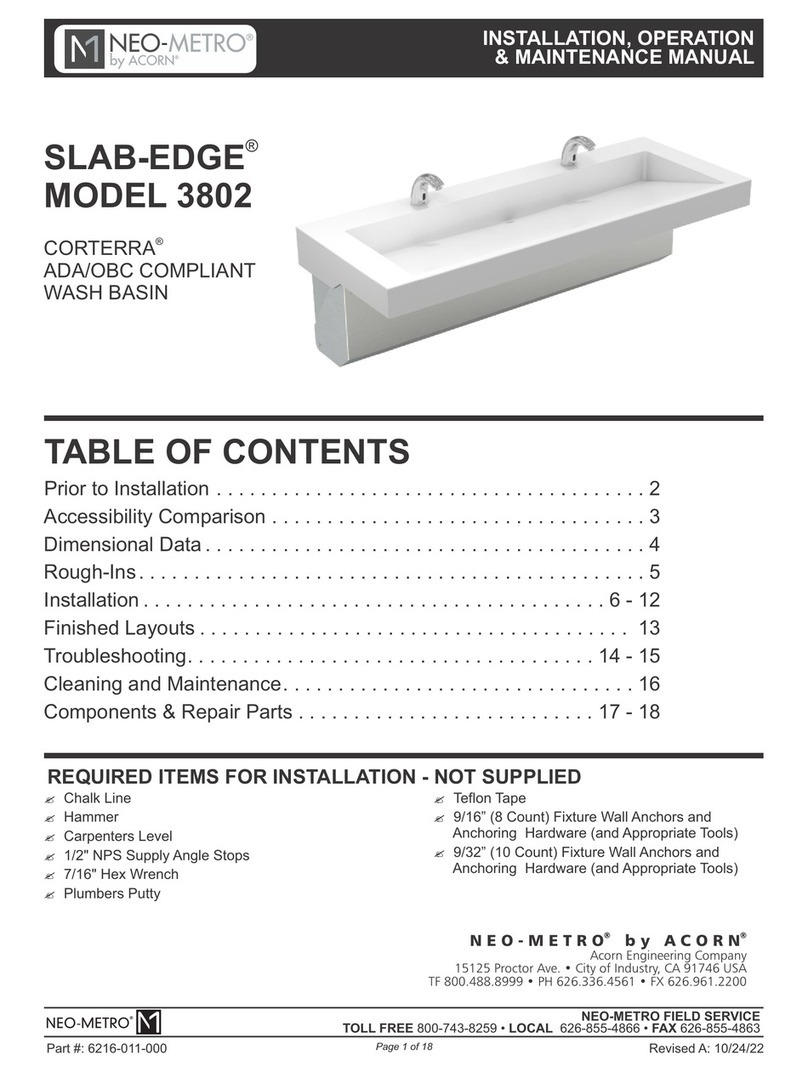
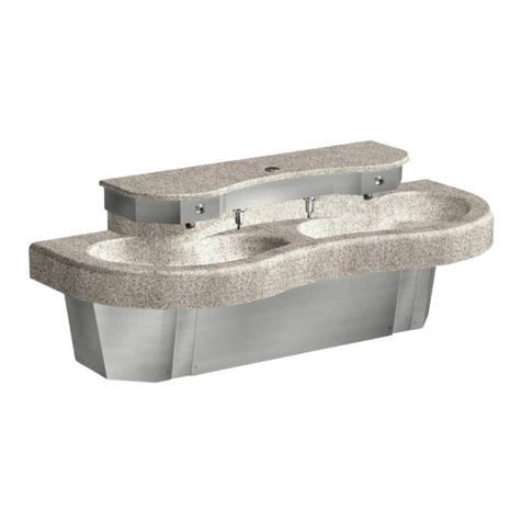
Acorn MERIDIAN 3793 Instruction manual

ACORN ENGINEERING FIELD SERVICE
TOLL FREE 800-743-8259 • LOCAL 626-855-4866 • FAX 626-855-4863
INSTALLATION, OPERATIONS & MAINTENANCE MANUAL
®
MERIDIAN 3793
Part #: 9927-143-001
Please visit www.acorneng.com
for most current specifications.
A C O R N E N G I N E E R I N G C O M P A N Y
P. O . B O X 3 5 2 7 • C I T Y O F I N D U S T R Y, C A 91 7 4 4 U . S . A .
T O L L F R E E 8 0 0 - 4 8 8 - 8 9 9 9 : : L O C A L 6 2 6 - 3 3 6 - 4 5 6 1
FA X 6 2 6 - 9 6 1 - 2 2 0 0 : : w w w. a c o r n e n g . c o m
A C O R N E N G I N E E R I N G C O M P A N Y
P. O . B O X 3 5 2 7 • C I T Y O F I N D U S T R Y, C A 91 7 4 4 U . S . A .
T O L L F R E E 8 0 0 - 4 8 8 - 8 9 9 9 : : L O C A L 6 2 6 - 3 3 6 - 4 5 6 1
FA X 6 2 6 - 9 6 1 - 2 2 0 0 : : w w w. a c o r n e n g . c o m
Accessibility Overview ....................................3
TABLE OF CONTENTS
Rough-Ins . . . . . . . . . . . . . . . . . . . . . . . . . . . . . . . . . . . . . . . . . . . 5 - 7
Installation . . . . . . . . . . . . . . . . . . . . . . . . . . . . . . . . . . . . . . . . . . 8 - 17
Piezo Adjustment. . . . . . . . . . . . . . . . . . . . . . . . . . . . . . . . . . . . . 18-20
Troubleshooting. . . . . . . . . . . . . . . . . . . . . . . . . . . . . . . . . . . . . 21 - 22
Dimensional Data........................................4
Cleaning and Maintenance................................23
Components & Repair Parts . . . . . . . . . . . . . . . . . . . . . . . . . . . 24 - 30
Warranty Information ....................................31
Prior to Installation.......................................2
REQUIRED ITEMS FOR INSTALLATION - NOT SUPPLIED
MODEL
®
CORTERRA
ADA-COMPLIANT
KURVE TRIPLE BASIN
®
MERIDIAN
3793
?Hammer
?1/2" NPS Supply Angle Stops And 1/2" NPS
Supply Flex Hose(s)
?Chalk Line
?Carpenters Level
?7/16" Hex Wrench
?1/4” Slotted Tip Screwdriver For Metering
Adjustment
?Driver For 1/4” Shank Bit - For Center Reject Bit
?Fixture Wall Anchors and Anchoring Hardware
(and Appropriate Tools) - For 3/8" Punching
(13 Count)
?Plumbers Putty
?Teflon Tape
REVISED: 03/07/19

ACORN ENGINEERING FIELD SERVICE
TOLL FREE 800-743-8259 • LOCAL 626-855-4866 • FAX 626-855-4863
INSTALLATION, OPERATIONS & MAINTENANCE MANUAL
®
MERIDIAN 3793
Please visit www.acorneng.com
for most current specifications.
Page 2 of 31
Part #: 9927-143-001
Prior to installation, supply lines must be flushed of all foreign material such as pipe
dope, chips, or solder. Debris or foreign material in water supply may damage valve.
Important: Some options may slightly alter installation. To ensure proper installation
review the manual thoroughly and verify rough-ins before beginning any work. File this
manual with the owner or maintenance personnel upon completion of installation.
Teflon tape is recommended on all threaded waste and supply connections to reduce the
possibility of leaks.
ANSI, UFAS or ADA compliance is subject to the interpretation and requirements of the
local code authority and is the responsibility of the installer for verification.
NOTE: Receptacle(s) must be wired to a GFCI protected circuit. Fixture must be earth
grounded per N.E.C. (National Electrical Code).
Industry standard wall backing, for wall hung fixtures, is required. Installer provided wall
anchors and wall anchoring hardware must be appropriate for wall construction, and
have a minimum pull-out rating of 1000 lbs. (453.6 kg).
T/P Mixing Valve Assembly: Recommended working water pressure is 30 psi (2.07 bars)
minimum to 125 psi (8.62 bars) maximum. Maximum hot water temperature is 180°F
(82°C). Temperature adjustment range is 85-115°F (29-46°C). Valve assembly must be
drained prior to being subjected to freezing temperatures. The valve assembly has
checks integral to the inlets however, angle stops are to be provided by the installer.
Single Temp Valve Assembly: Recommended working water pressure is 30 psi (2.07
bars) minimum to 100 psi (6.89 bars) maximum. Maximum temperature is 130°F
(54.4°C). Maximum outlet temperature is recommended is 105°F (40.6°C). Valve
assembly must be drained prior to being subjected to freezing temperatures. A
checkstop is provided with this valve assembly.
Provide 110-120VAC/60Hz/3A (MAX) electrical receptacle for factory supplied
120VAC/9VDC, 100mA plug-in transformer.
REVISED: 03/07/19

ACORN ENGINEERING FIELD SERVICE
TOLL FREE 800-743-8259 • LOCAL 626-855-4866 • FAX 626-855-4863
INSTALLATION, OPERATIONS & MAINTENANCE MANUAL
®
MERIDIAN 3793
Please visit www.acorneng.com
for most current specifications.
Page 3 of 31
ACCESSIBILITY OVERVIEW
Part #: 9927-143-001
ADA ages
6 thru 12
ADA
Adult
34" RIM
MAX.
4"
9"
121
2"
21"
21"
183
4"
27"
MIN.
21"
121
2"
4"
31" RIM
MAX.
24"
MIN.
21"
153
4"
21"
121
2"
4"
33" RIM
MAX.
29"
MIN.
21"
173
4"
9"
9"
OBC
REVISED: 03/07/19

ACORN ENGINEERING FIELD SERVICE
TOLL FREE 800-743-8259 • LOCAL 626-855-4866 • FAX 626-855-4863
INSTALLATION, OPERATIONS & MAINTENANCE MANUAL
®
MERIDIAN 3793
Please visit www.acorneng.com
for most current specifications.
Page 4 of 31
DIMENSIONAL DATA
12"
93
4"
111
4"
84"
21"
30"
30"
30"
27"
4"
151
4"
Part #: 9927-143-001 REVISED: 03/07/19

ACORN ENGINEERING FIELD SERVICE
TOLL FREE 800-743-8259 • LOCAL 626-855-4866 • FAX 626-855-4863
INSTALLATION, OPERATIONS & MAINTENANCE MANUAL
®
MERIDIAN 3793
Please visit www.acorneng.com
for most current specifications.
Page 5 of 31
ROUGH-IN DIMENSIONS -ADA (Adult)
E
D
C
B
A
Part #: 9927-143-001
- 3/8" Diameter Mounting Holes, For Anchoring Points, 10 Places.
-Waste Outlet for 1-1/2" O.D. P-Trap.
-120VAC, 60 Hz, 3A (Max.) GFCI Protected, Electrical Receptacle.
-Frame "V" Notch.
-Supply Stub-Outs with Stops for Valve 1/2" NPT Hot & Cold Supply Inlets.
34"
DECK
HEIGHT
273
8"241
2"25" 24"
197
8"
327
8"
11"
TYP.
19"
33"
TYP.
371
4"
TYP.
383
4"
13"
9"
3"
H C
E
D
C
B
A
REVISED: 03/07/19

ACORN ENGINEERING FIELD SERVICE
TOLL FREE 800-743-8259 • LOCAL 626-855-4866 • FAX 626-855-4863
INSTALLATION, OPERATIONS & MAINTENANCE MANUAL
®
MERIDIAN 3793
Please visit www.acorneng.com
for most current specifications.
Page 6 of 31
ROUGH-IN DIMENSIONS -ADA
AGES 6 THRU 12 YEARS
E
D
C
B
A
Part #: 9927-143-001
-Waste Outlet for 1-1/2" O.D. P-Trap.
-Supply Stub-Outs with Stops for Valve 1/2" NPT Hot & Cold Supply Inlets.
- 3/8" Diameter Mounting Holes, For Anchoring Points, 10 Places.
-120VAC, 60 Hz, 3A (Max.) GFCI Protected, Electrical Receptacle.
-Frame "V" Notch.
31"
DECK
HEIGHT
243
8"
211
2"22" 21"
167
8"
297
8"
11"
TYP.
19"
33"
TYP.
371
4"
TYP.
383
4"
13"
9"
3"
H C
E
D
C
B
A
REVISED: 03/07/19

ACORN ENGINEERING FIELD SERVICE
TOLL FREE 800-743-8259 • LOCAL 626-855-4866 • FAX 626-855-4863
INSTALLATION, OPERATIONS & MAINTENANCE MANUAL
®
MERIDIAN 3793
Please visit www.acorneng.com
for most current specifications.
Page 7 of 31
ROUGH-IN DIMENSIONS -OBC
ONTARIO BUILDING CODE
E
D
C
B
A
Part #: 9927-143-001
-Supply Stub-Outs with Stops for Valve 1/2" NPT Hot & Cold Supply Inlets.
- 3/8" Diameter Mounting Holes, For Anchoring Points, 10 Places.
-Waste Outlet for 1-1/2" O.D. P-Trap.
-120VAC, 60 Hz, 3A (Max.) GFCI Protected, Electrical Receptacle.
-Frame "V" Notch.
33"
DECK
HEIGHT
263
8"
231
2"24" 23"
187
8"
317
8"
11"
TYP.
19"
33"
TYP.
371
4"
TYP.
383
4"
13"
9"
3"
H C
E
D
C
B
A
REVISED: 03/07/19

ACORN ENGINEERING FIELD SERVICE
TOLL FREE 800-743-8259 • LOCAL 626-855-4866 • FAX 626-855-4863
INSTALLATION, OPERATIONS & MAINTENANCE MANUAL
®
MERIDIAN 3793
Please visit www.acorneng.com
for most current specifications.
Page 8 of 31
Part #: 9927-143-001
FIXTURE ANCHORING
DETAIL
B
DETAIL A
DETAIL C
Disassemble access panels and deck assembly
1from frame. Anchor frame to wall using 3/8”
mounting hardware by others.
-See DETAIL C. Assemble deck support flanges
to outside of frame using 1/4”-20 x 1” hex bolts,
1/4” lock washers, and 1/4” flat washers provided.
-See DETAIL A. Place deck assembly on frame,
2making sure angle engages behind frame joggle.
-See DETAIL B. Assemble underside of bowls to
frame with 1/4”-20 x 1/2” hex bolts, 1/4” lock
washers, and 1/4” fender washers provided.
Angle
Deck Support
Flanges
Frame Joggle
REVISED: 03/07/19

ACORN ENGINEERING FIELD SERVICE
TOLL FREE 800-743-8259 • LOCAL 626-855-4866 • FAX 626-855-4863
INSTALLATION, OPERATIONS & MAINTENANCE MANUAL
®
MERIDIAN 3793
Please visit www.acorneng.com
for most current specifications.
1
2
3
4
4
3
5
HINT: Teflon tape is recommended on all threaded waste and
supply connections.
Page 9 of 31
NOTE: Continuous waste assembly will require field cutting and
fitting by the installer.
27"
21"
54"
6"
Part #: 9927-143-001
Install grid strainer and close elbow to bowl
3using plumber's putty.
à 1-1/2" -16 UNI Rough Chrome
Brass Jam Nut
Ä 1-1/2"-16 x 1-1/4" UNI Close Ell
with 3/8" NPT Clean-Out Plug
Á Rubber Gasket
 Flat Fiber Washer
À Grid Strainer w/ 1-1/2" -16
UNE Threads
Assemble continuous waste piping using teflon
4tape on all threaded connections and make up
waste connections to 1-1/2” P-trap.
REVISED: 03/07/19

ACORN ENGINEERING FIELD SERVICE
TOLL FREE 800-743-8259 • LOCAL 626-855-4866 • FAX 626-855-4863
INSTALLATION, OPERATIONS & MAINTENANCE MANUAL
®
MERIDIAN 3793
Please visit www.acorneng.com
for most current specifications.
VALVE INSTALLATION
MX-TP VALVE (-H HAND OPERATED SHOWN)
-ST SINGLE TEMPERATURE VALVE (-H HAND OPERATED SHOWN)
!IMPORTANT
Page 10 of 31
Part #: 9927-143-001
Before making up the supply
connections, the supply lines
must be flushed of all foreign
material such as pipe dope,
pipe chips, solder, sand, etc.
for MX-TP Valve, install valve using 1/4” Flat
AWasher, 1/4” Lock Washer and 1/4”-20 Hex Nut
provided 1/2” NPS supply hoses to valve.
provided. Flush Supply lines. Connect installer
for -ST Single Temperature valves, Install valve assembly in fixture using 1/4”
BFlat Washer, 1/4” lock Washer and 1/4”-20 Hex Nuts provided. Flush supply
lines. Connect installer provided 1/2” NPS hose to valve.
VALVE ASSEMBLY
VALVE ASSEMBLY
REVISED: 03/07/19

ACORN ENGINEERING FIELD SERVICE
TOLL FREE 800-743-8259 • LOCAL 626-855-4866 • FAX 626-855-4863
INSTALLATION, OPERATIONS & MAINTENANCE MANUAL
®
MERIDIAN 3793
Please visit www.acorneng.com
for most current specifications.
Page 11 of 31
VALVE INSTALLATION & ADJUSTMENT
Part #: 9927-143-001
2) Connect hot and cold water to supply
valve using 1/2” NPTE connections.
5) Turn on fixture and allow water to flow for 2
minutes. Measure water temperature at
outlet. If water is not at desired temperature,
adjust as necessary.
3) Connect outlet of tempering valve to
spout(s) using 1/4” O.D. tube connections
provided.
NOTE: Installation should be in accordance with
accepted plumbing practices.
1) Locate suitable place for mounting the valve
assembly. Valve assembly should be
accessible for service and adjustment and
as close to the point-of-use as possible.
Wall anchors and anchoring hardware, for
Ø3/8” mounting holes, provided by installer.
4) Turn on hot and cold water supplies. If any
leaks are observed, hand tighten
connections as necessary to stop leaks
before proceeding.
1) Loosen locknut.
4) Tighten locknut to prevent accidental or
unauthorized temperature adjustment.
5) Re-check outlet temperature.
2) Turn on fixture and run water for at least 2
minutes. Allow supply temperature to
stabilize.
3) Turn temperature stem counter-clockwise
for hotter or clockwise for colder outlet
temperature.
Temperature Adjustment:
Valve Assembly Installation: !IMPORTANT
Flush supply lines of all foreign material such
as pipe dope, pipe chips, solder, sand etc.
before making up supply connections.
HINT: Angle stops are recommended
and is the responsibility of the installer.
LOCKNUT
WARMER
TEMPERATURE
STEM
REVISED: 03/07/19

ACORN ENGINEERING FIELD SERVICE
TOLL FREE 800-743-8259 • LOCAL 626-855-4866 • FAX 626-855-4863
INSTALLATION, OPERATIONS & MAINTENANCE MANUAL
®
MERIDIAN 3793
Please visit www.acorneng.com
for most current specifications.
-SO Sensor Operation
Range Adjustment
5. Hold hand at desired sensing distance until red light
stops flashing and solenoid activates.
See DETAIL C.
4. Move hand to desired sensing distance.
See DETAIL B.
2. Connect power supply to sensor. Red light should
be flashing.
1. Make sure power supply is disconnected from
sensor and make short circuit on red wires.
See DETAIL A.
3. Move hand in front of sensor to distance of 2” to 4”
within 5 seconds and wait until red light flashes
quickly.
DETAIL A
DETAIL B
DETAIL C
Transformer must
be plugged into a
GFI protected
circuit. Fixture must
be earth grounded
per N.E.C. or
applicable codes.
Jumper
By Others
-SO Sensor Operation or -PPZ Programmable Piezo Pushbutton
Page 12 of 31
SENSOR OPERATION & CONNECTIONS
Part #: 9927-143-001 REVISED: 03/07/19
-SO SENSOR
-PPZ PUSHBUTTON
RED BLUE
RED
BLUE
TRANSFORMER
SOLENOID VALVE

ACORN ENGINEERING FIELD SERVICE
TOLL FREE 800-743-8259 • LOCAL 626-855-4866 • FAX 626-855-4863
INSTALLATION, OPERATIONS & MAINTENANCE MANUAL
®
MERIDIAN 3793
Please visit www.acorneng.com
for most current specifications.
To service or install batteries
remove access panel by
removing (4) 10-32 x 3/4"
screws from front of fixture
using allen head bit provided
(socket & driver by others).
Replace access panel when
finished.
-SO-BAT
Sensor Operation Battery Powered
Page 13 of 31
SENSOR OPERATION & CONNECTIONS -BATTERY OP
Acorn does not provide batteries for -BAT units.
Each station requires (6) AA batteries.
Part #: 9927-143-001 REVISED: 03/07/19
-SO SENSOR
-PPZ PUSHBUTTON
RED BLUE
RED
BLUE
TRANSFORMER
SOLENOID VALVE

ACORN ENGINEERING FIELD SERVICE
TOLL FREE 800-743-8259 • LOCAL 626-855-4866 • FAX 626-855-4863
INSTALLATION, OPERATIONS & MAINTENANCE MANUAL
®
MERIDIAN 3793
Please visit www.acorneng.com
for most current specifications.
Ferrule Nut
1/4"
Min.
Ferrule
Nut
-H Hand Operated
1/8" O.D. AIR TUBE
1/4" O.D. WATER LINE
Leave a minimum 1/4” of polyethylene tubing
through the Ferrule Nut on the pushbutton
assembly. This is necessary to ensure proper
tubing connection.
Page 14 of 31
turn timing screw.
Timing Screw
To adjust timing,
HAND OPERATION & CONNECTIONS
Turn timing screw clockwise to
increase timing.
Do not over tighten
ferrule nuts.
Part #: 9927-143-001 REVISED: 03/07/19

ACORN ENGINEERING FIELD SERVICE
TOLL FREE 800-743-8259 • LOCAL 626-855-4866 • FAX 626-855-4863
INSTALLATION, OPERATIONS & MAINTENANCE MANUAL
®
MERIDIAN 3793
Please visit www.acorneng.com
for most current specifications.
ACCESS PANEL INSTALLATION
Page 15 of 31
Install front and side access panels using 10-32 x 3/4" center reject hex head screws provided.
Part #: 9927-143-001 REVISED: 03/07/19

ACORN ENGINEERING FIELD SERVICE
TOLL FREE 800-743-8259 • LOCAL 626-855-4866 • FAX 626-855-4863
INSTALLATION, OPERATIONS & MAINTENANCE MANUAL
®
MERIDIAN 3793
Please visit www.acorneng.com
for most current specifications.
Page 16 of 31
-DV SOAP OPTION RETRO-FIT & INSTALLATION
Part #: 9927-143-001
Remove Access Plug
Install soap filler
NOTE: Soap Tank Capacity = 1 Gallon
Remove Corterra Plug
Install Soap Tank
Some soaps contain corrosive additives that can cause rust in soap dispensers.
Acorn Engineering Company recommends user/ maintenance personnel review
MSDS reports of soap and possible corrosive additives noted.
Do not exceed the capacity of the soap tank. Overfilling may result in spilling and pooling of soap
solution within the sprayhead enclosure and outside the tank.
!WARNING
Remove Corterra plug from
2top cover and soap access
plug from bottom of
sprayhead enclosure.
Position and install soap
3tank in sprayhead
enclosure as shown and
install soap dispenser by
aligning dispenser with
drain adapter and fixing
with set screws as shown
Install soap filler assembly
4to top cover and replace.
Fill soap tank by removing
5filler cap and pouring soap
directly into tank. Do NOT
overfill.
Remove top cover from
1unit. To remove cover, use
Allen head bit provided and
unscrew 10-32 x 3/4" long
vandal resistant fasteners
shown. Hex bit driver is
installer provided.
Sprayhead
Enclosure
Install Soap Dispenser
REVISED: 03/07/19

ACORN ENGINEERING FIELD SERVICE
TOLL FREE 800-743-8259 • LOCAL 626-855-4866 • FAX 626-855-4863
INSTALLATION, OPERATIONS & MAINTENANCE MANUAL
®
MERIDIAN 3793
Please visit www.acorneng.com
for most current specifications.
Optional -KP Kick Plate Rough-Ins
Optional -KP Kick Plate Installation
Page 17 of 31
Part #: 9927-143-001
H C
B
A
DIM
"A"
11"
DIM
"A"
DECK
HEIGHT
15" 34"
14-1/2" 33"
13" 31"
Sink Mounting Frame, Shown For Reference.
Ø1/4" x 3/8" Long Slots For Installer Provided
Wall Anchors And Anchoring Hardware.
A
B
321
2"
TYP.
REVISED: 03/07/19

ACORN ENGINEERING FIELD SERVICE
TOLL FREE 800-743-8259 • LOCAL 626-855-4866 • FAX 626-855-4863
INSTALLATION, OPERATIONS & MAINTENANCE MANUAL
Please visit www.acorneng.com
for most current specifications.
Programable Piezo Pushbutton
Programming Instructions (Flow Time Adjustment)
As soon as the cable is reconnected the LED will start flashing, it will flash 4 times, then stays on for 3 seconds.
During the 3 second period, push the piezo button once, the LED will go out, now you are in the 1 sec timing mode
and each time the button is pushed the LED will flash, adding 1 sec to the total timing cycle.
To move on to the 5 sec timing mode, pause and wait for the LED to flash 2 times, now you are in the 5 sec timing
mode. Each time the button is pushed the LED will flash, adding 5 sec to the total timing cycle.
To program the piezo pushbutton, you will need to be able to see the back of the piezo pushbutton.
To move on to the 20 sec timing mode, pause and wait for the LED to flash 3 times, now you are in the 20 sec timing
mode and each time the button is pushed the LED will flash, adding 20 sec to the total timing cycle. After programing
is complete, pause and wait for the LED to flash 4 times and then 5 times, which completes the programming.
— When a timing mode is not required then do not push the button and wait for the next timing mode.
— 5 second timing mode: Each push of the button adds 5 seconds to the total timing cycle.
THE TIME SETTINGS PROGRAM USES 3 DIFFERENT TIMING MODES:
Prevision must be made to access the back of the piezo pushbutton. There is an LED on the back of the piezo
pushbutton under a layer of transparent epoxy, used as a programming indicator light.
— 1 second timing mode: Each push of the button adds 1 second to the total timing cycle.
— Each timing mode (1 sec, 5 sec or 20 sec timing mode) can be sequenced up to 100 times, that is
the number of times, the button can be pushed, to increase the total timing cycle in each timing mode.
— 20 second timing mode: Each push of the button adds 20 seconds to the total timing cycle.
In order to start the programming the piezo pushbutton, the button must be powered down. Disconnect the red power
cable and wait 20 seconds, then reconnect the red power cable.
NOTE: This programming procedure moves along rapidly, there is
only about 2 or 3 seconds between programming operations.
The Button is factory set an 8 sec. timing cycle, if an 8 sec. cycle is adequate, then no programming adjustment
is required.
NOTE: Read the entire document before
trying to program the piezo pushbutton.
Page 18 of 31
Part #: 9927-143-001
®
MERIDIAN 3793
REVISED: 03/07/19

ACORN ENGINEERING FIELD SERVICE
TOLL FREE 800-743-8259 • LOCAL 626-855-4866 • FAX 626-855-4863
INSTALLATION, OPERATIONS & MAINTENANCE MANUAL
Please visit www.acorneng.com
for most current specifications.
Determine the
number of seconds
per timing cycle
1 Push = 1 Second
x 1 = sec
Fill in all the
Boxes below
1 Push = 5 Seconds
x 5 = sec
ADD
1 Push = 20 Seconds
x 20 = sec
ADD
Total timing cycle equals
seconds
EQUALS
Ÿ Reconnect power.
Ÿ LED flashes, then stay on.
PROGRAMING STEPS:
— Power down piezo button for 10 seconds.
Ÿ You are in the 1 sec timing mode, immediately push the button, 1 push
equals 1 sec added to the total timing cycle.
Ÿ LED turns off.
Ÿ Pause and wait for the LED to flash 2 times.
Ÿ While the LED is steady on, push button.
Ÿ You are in the 5 sec timing mode, immediately push the button, 1 push
equals 5 sec added to the total timing cycle.
Ÿ Pause and wait for the LED to flash 3 times.
Ÿ You are in the 20 sec timing mode, immediately push the button, 1
push equals 20 sec added to the total timing cycle.
Programmable Piezo Pushbutton
Programming Instructions (Flow Time Adjustment)
WORKSHEET
(FILL IN ALL BOXES, WHICH WILL SIMPLIFY THE PROGRAMMING PROCEDURE)
Page 19 of 31
Part #: 9927-143-001
®
MERIDIAN 3793
REVISED: 03/07/19

ACORN ENGINEERING FIELD SERVICE
TOLL FREE 800-743-8259 • LOCAL 626-855-4866 • FAX 626-855-4863
INSTALLATION, OPERATIONS & MAINTENANCE MANUAL
Please visit www.acorneng.com
for most current specifications.
BLACK
RED
BLACK SOLENOID
CABLE
RED POWER
CABLE
PROGRAMMING INDICATOR
LED LIGHT
TRANSPARENT
EPOXY FILLING
PIEZO
PUSHBUTTON
Page 20 of 31
Part #: 9927-143-001
®
MERIDIAN 3793
REVISED: 03/07/19
Other manuals for MERIDIAN 3793
1
Table of contents
Other Acorn Plumbing Product manuals

Acorn
Acorn MERIDIAN 3752 CORTERRA Instruction manual

Acorn
Acorn Meridian 3791-LO User manual
Acorn
Acorn NEO-METRO SLAB-EDGE 3802 Instruction manual

Acorn
Acorn Neo-Metro WEDGE WSW130 Instruction manual
Acorn
Acorn Meridian 3792 Instruction manual

Acorn
Acorn Terrazzo-Ware SB Series Instruction manual

Acorn
Acorn MERIDIAN 3793 User manual
Acorn
Acorn MERIDIAN 3753-HLH User manual
Acorn
Acorn MERIDIAN 3791-RO Instruction manual

Acorn
Acorn Meridian Corterra 3751 Instruction manual