Acoustical Manufacturing Co. Quad 34 User manual
34
CONTROL
I]NIT
INSTRUCTION
BOOK
ALTAD

CONTENTS
INTRODUCTION
GUARANTEE
SERVICE
ACCESSORIESSUPPLIED
INSTALLATION
Ghecking
the
AGPower
Supply
Connecting
tothe
ACPower
Supply
ACPowerOut
Positioning
the
GontrolUnit
GonnectiontotheAmplifier
Changing
Output
Level
SignalGonnections
SWITCHINGONANDOFF
CONTROLFUNCTIONS
Volume
Balance
ilono
Titt
BassLift/Step
Filterc
TAPERECORDERS
Recording
Monitoring
MAINTENANCE
FRONTAND
REARVIEW
Connecting
Sockets
SPECIFICATION
Tilt,Bass
LifUStepandFilter
Graphs
page
2
2
2
3
3
3
3
3
4
4
5
5
5
5
6
6
6
6
6
6
6
6
6
6
7
7
8
inside
backcover
inside
backcover
ACCESSORTES
page
1
INTRODUCTION
GUARANTEE
SERVICE
The
Quad
34
is
ahigh
quality
controlunit
withinputs
forCD
player,
tuner,tape
recorderanddisc.Therequiredinputisselectedbylightaction
press
buttons
andallswitchingissolidstateformaximumreliabili$andsilentselection.
Volumeadjustmentisbya
precision
steppedrotary
control.
Pressbuttonfilters
togetherwithrotarytilt,bassandbalancecontrolsenable
the
listenertocorrect
for
certain
room
effectsand
programme
balance
ProvisionismadeforchangingthesensitivityoftheCDinputandthetape
recorderinpuUoutputbyreplacing
plug-in
'flags'
(resistors)
intoresistorsockets
onthemaincircuitboard.
The
performance
ofthe
Quad
34controlunit
is
asaccurateas
itis
possible
to
achievebycarefuldesign,
selectionofcomponentsandrigoroustestprocedures.
The
Quad
34controlunitisguaranteed
fortwelvemonthsfromthedate
of
purchase.
Withinthis
period
weundertake
to
supply
replacement
parts
freeof
charge
provided
thatthe failure
was notcausedby misuse,accidentor
negligence.Returnfreightandthird
party
labour
costsare
notcoveredunless
by
localagreement.
WithintheUKthis
guarantee
doesnot
limit
your
statutory
rights.Aseparate
guarantee
cardis notsuppliedand
yourguarantee
beginsonthedayof
purchase.
lfthecontrolunitrequires
serviceitshouldbereturnedtothesupplier,
the
distributorforthecountry
of
purchase
or
Quad
Electroacoustics
Ltd.
Pleaseencloseabrief
note
givingyour
nameandaddressandthe
reasonfor
returningit.
Quad
offerasameday
servicefromMondaytoFridayexcept
forBankholidays.
Pleasecontactustomakeanappointment.
lmportant Retaintheoriginalcartonand
internal
packing
incasethecontrol
unithastobe
returnedforservice.
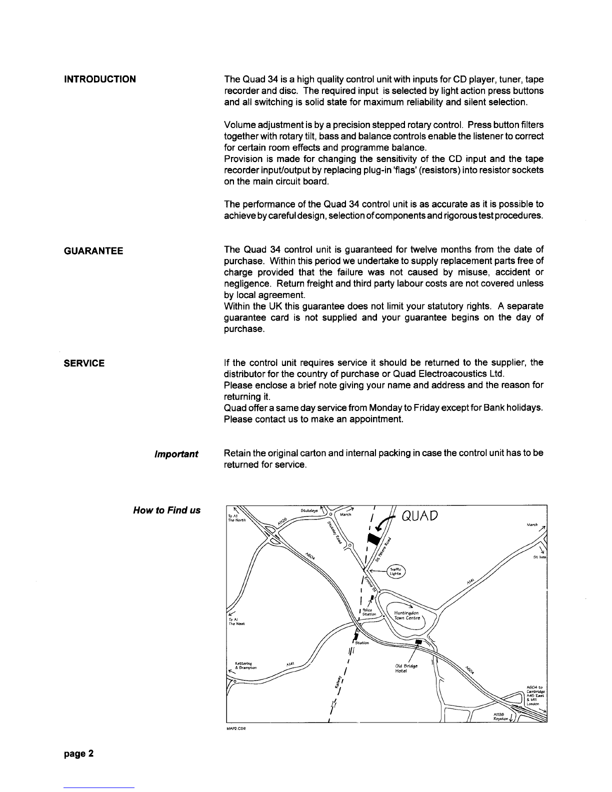
Howto Find us
page
2
ACCESSORIES
SUPPLIED
INSTALLATION
AC
supplylead
2mlong
ACEuro
typeoutput
connector
2x100mVrecord
flags
2x100
mVreplay
flags
Type
No. QUKES2B
TypeNo. PPR0413
TypeNo. Q34100R
Type
No. Q34100P
The
34control
unitisdesigned
tooperate
ononerange
ofAC
powersupply
only,
50/60Hz.
either200-240V
or1001120V
.Thecorrect
operating
voltageis
ctearty
marked
ontheback.ltmaybechanged
from220V
to110V
operationorvice
versa
byasuitably
qualified
technician.
Before
connecting
to theACpower supplycheck
that thevoltage
range
marked
on thebackcorresponds
with thatof thesupply.
The34
controlunitis
suppliedwith
anAC
power
leadwith
a13A3
pinplug
with
13Afuse.
Donot
cutoffthis
plug
oruseitwith
itsfuse
coverremoved.
lfhowever
for
anyreason
the
plug
has
toberemoved
thenitmust
bedisposed
ofandunder
no circumstances
plugged
into
a 13A
socket
outlet.Asuitable
plug
canbe
fitted,as
explained
below:-
WARNING:
THISAPPARATUS
MUSTBE
EARTHED
IMPORTANT
-Fitting
amains
ptug.
Thewires
inthemains
lead
arecoloured:
Brown=Live Blue
= Neutral GreenMellow
= Earth
TheBrownwire
must
beconnected
totheterminal
marked
Lorcoloured
Red.
TheBlue
wiremust
beconnected
totheterminal
marked
NorcolouredBlack.
The GreenNellow
wiremustbe connected
to theterminal
markedE or
colouredGreen
orGreenl/ellow.
Whenafused
13A
plug
isused
a13A
fuse
(ASTA
approved
to8S1362)
willbe
adequatefor
atypical
Quad
system.
Forother
types
of
plug,
then
fita13Afuse
eitherin
the
plug,
oradaptor,or
atthedistribution
board.lfin
doubtconsult
a
qualified
electrician.
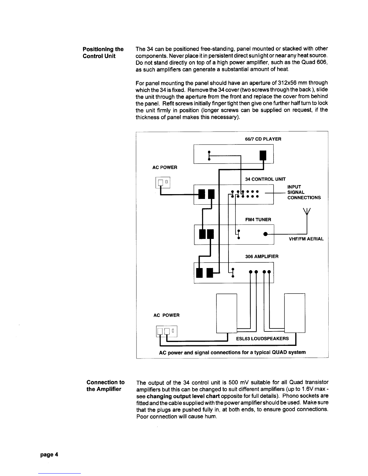
The
control
unitisfitted
withaswitched
Ac power
outsocketforfeeding
other
units
inthesystem.
Quad
power
amplifiers
and
tuners
are
provided
withthe
appropriate
interconnecting
cablesand
thediagram
overleaf
shows
howthe
unitsshould
belinked
together.
lfrequired
aspare
ACoutput
connectoris
provided
which
shouldbe
wiredas
shown
inthediagram
below.
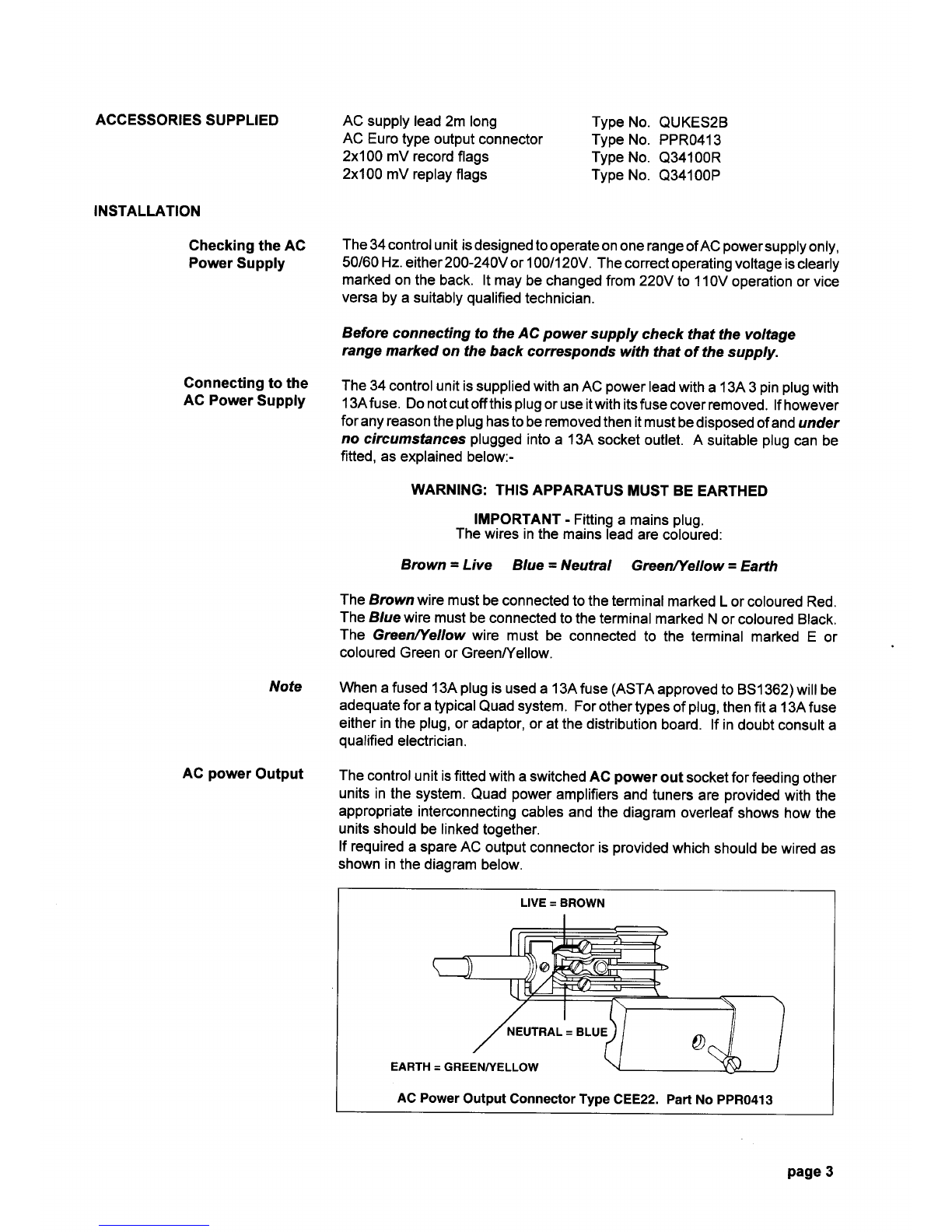
LIVE
= BROWN
ACPower
Output
ConnectorType
CEE22.Part
No
ppR0413
Checking
theAG
Power
Supply
Connecting
tothe
AGPower
Supply
Note
AG
power
Output
page
3
Positioning
the
GontrolUnit
Gonnection
to
the
Amplifier
The34canbe
positioned
free-standing,
panel
mountedorstacked
withother
components.
Never
place
itin
persistent
directsunlightor
nearanyheat
source.
Donotstand
directlyon
topofahigh
power
amplifier,such
asthe
Quad
606,
as
suchamplifiers
can
generate
asubstantialamount
ofheat.
For
panel
mountingthe
panel
should
haveanapertureof
312x56
mmthrough
whichthe34
isfixed.Remove
the34cover
(two
screwsthrough
theback
),
slide
theunitthrough
theaperture
fromthe
frontandreplacethe
cover
frombehind
thepanel.
Refitscrewsinitiallyfingertightthengiveonefurtherhalfturntolock
theunit
firmlyinposition(longer
screwscanbesupplied
onrequest,ifthe
thickness
of
panel
makesthis
necessary).
6617CD PLAYER
AC
power
andsignal
connections
foratypicalQUAD
system
The outputof the 34 control
unit is 500 mV suitable
for all Quadtransistor
amplifiersbut
thiscanbe
changedto
suitdifferentamplifiers
(up
to1.6V
max
-
seechanging output levelchart opposite
forfulldetails).
Phonosockets
are
fitted
andthecable
supplied
withthe
power
amplifiershould
beused.
Makesure
that
theplugs
are
pushed
fullyin,atboth
ends,to ensure
good
connections.
Poorconnection
willcause
hum.
page4
Table of contents


