Acoustical Systems AQUILAR Series User manual

1
10” and 12” reference tonearm
©
the AOUILAR
picture by Harry Ralston
owner’s manual

picture by
Moritz Teichmann
A brief word
from the designer
My thanks and congratulations to you for choosing the AQUILAR.
The AQUILAR is the result of my more than 35 years of intimate research and
preoccupation with analog playback - with the specic focus on the interaction of the
record groove with the cartridge and tonearm.
The AQUILAR in both versions - the 10” and 12” effective length - is the direct
derivate and distillate from our 12” AXIOM tonearm introduced in 2012.
A truely universal tonearm, which offers all and every option of alignment –
while ensuring the best possible mechanical guidance for any cartridge.
Taking into account the paramount importance of energy transfer in relation to
effective moving mass.
Resulting in a level of performance only obtainable, when each and every aspect
of the analog audio tracking process is attended to with utmost attention to every
minute detail.
A level of performance, which transcends prior frontiers and opens new levels of
musical realism in the playback of recorded music.
We do share the real passion for music and I am condent that the AQUILAR will
allow you to hear and enjoy your favorite records like never before.
Please get yourself accustomed with this manual.
Make sure you familiarise yourself with each and every aspect of the AQUILAR’s
options.
Your time will be rewarded with outstanding performance, to the benet of your
whole analog set-up and ultimately your enjoyment of recorded music.
The AQUILAR is entirely designed, manufactured and assembled with care and
dedication in Bavaria, Germany.
Kind regards
D. D. Brakemeier

Content
Technical features & general design 4
Alignments 4
Step-by-step procedures 5
Single point mounting vs. SME slide base 5
Unpacking the AQUILAR 6
Mounting the AQUILAR 7
Levelling the AQUILAR’s pivot 18
Raising or lowering the pivot plane 19
Removing the ngerlift 21
Exchanging the cartridge mounting plate 22
Setting antiskating 22
Specications 23
AQUILAR alignment template 24
General note:
Technical data, minor design and specications are subject
to change without prior notice.
copyright & design: acoustical systems
Manufactured and assembled in Germany
For further infomations:
www.acoustical-systems.com, info@acoustical-systems.com
11/2017

4
Technical features
& general design
The AQUILAR is a pivot tonearm featuring a
double nano-gimbal bearing architecture.
The AQUILAR is a static, full lateral balanced
design.
The AQUILAR features an unique compound
arm wand - a combination of surface hardened
Titanium and Carbon Fiber pipes blocked
together and internally damped by an all new
design concept, a concept never before
applied in tonearm design and rst featured
in the AXIOM resulting in unmatched fast
energy transfer and total absence of any
parasitic resonances in the tonearm.
The AQUILAR was designed to explore the
possibilities of analog playback to the utmost
degree. To accomplish the best possible analog
playback performance, the AQUILAR offers an
unique complete set of alignment features.
Alignments
Leveling the bearing axis
The AQUILAR can be precisely leveled by
the user, independent from the turntable or
mounting surface. This is essential to avoid
parasitic side-forces prior to alignment and
antiskating setting.
SRA/VTA adjusted at the
cartridge
In the AQUILAR the important alignment(s)
of VTA / SRA can be made at the cartridge –
without altering the static parameters of
the tonearm, while preserving the other set
alignments and leaving the arm wand always
horizontal. This again is of paramount
importance in a static balanced design to avoid
unwanted changes in static settings (namely
tracking force) when changing tonearm height
to accommodate VTA or SRA.
Offset and Overhang
adjustment
Offset is adjusted in the prolonged and slightly
widened slots for the cartridge mounting screws.
Overhang can be adjusted at 2 spots,
both located at the head. First of course in the
prolonged 1/2” slots for the cartridge
mounting screws. Here the slots allow for up
to 5 mm adjustment in overhang and thus
effective length. The 2nd spot is at the collar
of the headshell where it is clamped to the arm
wand. This is an additional spot for further over-
hang adjustment only IF NEEDED.
The whole headshell can be moved back and
forth by up to another 5 mm in this way.
This should hardly ever be necessary.
Azimuth
The headshell’s collar is also the point for
azimuth adjustment. By loosening the clamp
screw the user may rotate the whole headshell in
either direction.
Small indication marks at the rear of the
headshell’s collar and on top of the arm wand
allow for reference and easy return to former
settings.
Dynamic anti-skating
Skating compensation – or anti-skating –
adjustment in the AQUILAR is dynamic and
follows the tangential geometry of the
AQUILAR. If carefully operated, it can be
adjusted during play. However we recommend
that you do ALL adjustment or alignment at the
AQUILAR ONLY with the cartridge / stylus
lifted off the record.

5
Tonearm height – VTA
Tonearm height can be adjusted on the main
VTA-tower of the AQUILAR.
One full turn of the large top knob adjusts
height by precisely 1 mm.
Tangential alignment
It is possible to align the AQUILAR to the
standard tangential curves of Baerwald,
Stevenson or Loefgren in any version and
standard.
The absolute best possible performance
however is obtained only by aligning the
AQUILAR to the new UNI-DIN tangential
curve.
It’s geometric design is uniquely based on
the UNI-DIN, a tangential curve formulated
in 2011.
Step-by-step
procedures
In the next pages I would like to take you
through the mounting and alignment options of
the AQUILAR.
All procedures are illustrated step-by-step.
The pictures will give you most all of the
information you need to perfectly mount and
set-up the AQUILAR.
However, I will guide you through this with
my comments too and try to give further
information whenever the mere picture may
not tell the whole story.
We all like to get a new tool working as fast as
possible.
May I please encourage you to follow me
through this mounting and set-up procedure as
precisely as possible and to the very end - it will
be to your advantage.
This will ensure that you get the best
possible performance from your AQUILAR
and take advantage of all its features and
capabilities.
Single-point mounting vs.
SME slide base
In this manual we will cover the AQUILAR
mounting with the standard 1-point mounting.
In addition there is the option to mount the
AQUILAR easily onto any existing 9” or 10”
SME armboard.
We do offer - as a special order item - a
dedicated SME-slide base for the AQUILAR.
If interested, please ask your dealer for the
SME-slide base for the AQUILAR.
There is no difference in performance between
the 2 mounting options.
We further offer other adaptor mounting plates
for existing armboards upon your request.
If you are in need of a mounting plate for other
existing armboards - to take advantage of
existing pre-drilled armboards - please kindly
check back with your dealer who will contact
us.
GENERAL NOTE
Please make sure prior to setting up
the AQUILAR that your turntable’s
platter and armboard are dead level.
6
Unpacking the
AQUILAR
Please make sure that all parts are present
by unpacking the AQUILAR and all its tools
and accessories:
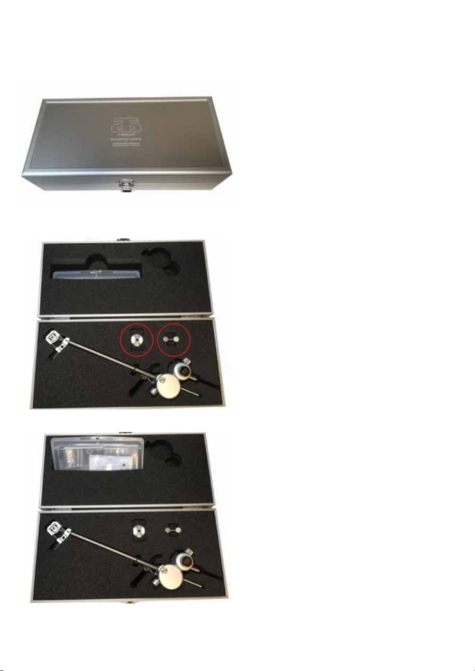
The AQUILAR suitcase
containing the following:
• the AQUILAR tonearm
• the main HD18 counter weight
• (2) Lateral balance weights
(1) stainless steel, (1) aluminum
• the AQUILAR’s accessory box
The AQUILAR’s accessory box
containing the following:
• AQUILAR alignment template
- detailed description on page 24 -
• (2) black knob ngerscrews
• (2) stainless steel countersunk screws
• (1) white knob ngerscrew with sharp tip
in 8 mm sleeve
• (1) white 20 mm POM adapter
• (2) small white 7 mm spindle hood
• (1) additional 40 mm length stainless
steel lateral rod for heavy cartridge
counterbalancing
• (1) 100 mm long, 3 mm stainless steel pin
• plastic bag with (2) distance stands
• (4) 90° Allen wrenches -
metric sizes 0.89, 1.5, 2.0 and 4.0
• (1) small diameter spirit level
for use on tonearm bearing pivot
7
• (1) 20 mm round dial scale for SRA / VTA
adjustment at headshell
• (3) special M5 mounting screws with
- (1) 20 mm length
- (1) 25 mm length
- (1) 30 mm length
• (1) set of M5 washer and spring ring
Mounting the
AQUILAR
The AQUILAR is mounted with 1 M5 screw
and 1 set of stainless steel washer and spring
ring only.
All you need is a single 5 mm hole in your
armboard to mount the AQUILAR on your
turntable.
Please take the AQUILAR from its packing
and place it like pictured above.
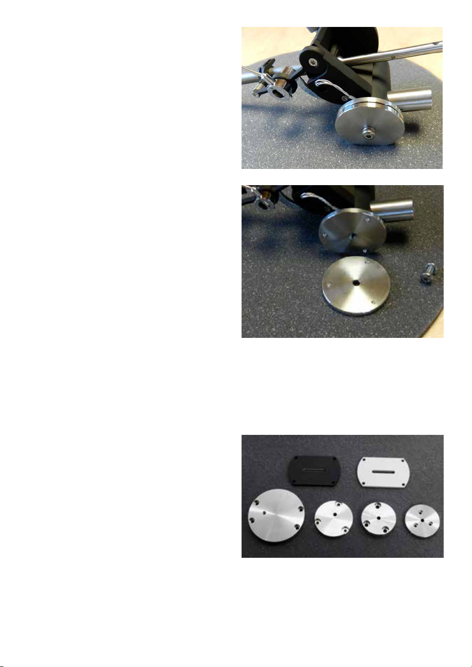
Now remove the screw in the bottom of
the mounting plate.
Select 1 of the M5 screws in the accessory
box suitable for your armboard. The M5 screw
should be at least 8 mm (1/3”) greater in length
than your armboard’s thickness.
Now take the stainless steel lower mounting
plate and look at it.
The 3 indents have to point upward.
Please take this 50 mm lower mounting plate
and place it onto your armboard with the 3
indents pointing upwards.
The 5 mm center hole should be placed directly
over the 5 mm mounting hole.
Please note: There is a selection of
mounting plates available to accommo-
date existing arm boards - please ask your
dealer for details.
upper row: SME - slide base
lower row: mounting plates for
Kronos, Jelco, Tri-Planar and Brinkmann

8
Take the selected 20 - 30 mm length M5 screw
with spring ring and washer attached.
Put it up through the suitable center hole on
the turntable mounting board and through
the center hole in the stainless steel lower
mounting plate (3).
Place the whole AQUILAR assembly directly
on top of the M5 screw and secure it in place
by screwing the M5 screw upwards through the
hole in armboard, through the lower mounting
plate into the center pillar of the AQUILAR.
Make sure to position the lower mounting plate
with the indents as pictured (4).
That way you can easily align the 3 levelling
spikes in the upper mounting plate in the
correct position towards the matching indents in
the lower mounting plate.
PLEASE NOTE
The 3 spikes MUST sit in the matching
indentions in the lower mounting plate.
Now tighten the mounting screw JUST A BIT -
not anywhere near maximum strength.
Do not use maximum force, just make sure it is
loosely tightened so that the mounting plate can
still be rotated in the horizontal plane.
The mounting screw will be xed
during levelling the pivot plane.
The AQUILAR is now sitting in place.
If you use the AQUILAR’s alignment
template - detailed description on page 24 -
to determine the mounting distance, please insert
the 100 mm stainless steel pin careful into the
dedicated hole next to the thread for the position-
ing screw. Sharp tip downwards - open M3 thread
pointing upwards (1).
The pin has a sharp tip - be careful! -
this can be used to mark the desiered spot on the
armboard. A controlled gentle hit with a small
hammer on the end of the pin will do (2).
1
2
3
4

9
Now use the AQUILAR’s dedicated
alignment template (description on
page 24).
Please see picture for reference - you will
nd all needed mounting gear and tools in the
accessory box.
On top of the AQUILAR’s bearing house is a
12 mm diameter stainless steel plate with a
small center hole. This center hole clearly marks
the pivot center of the AQUILAR (1).
First place the AQUILAR’s alignment
template - with 20 mm white POM spindle ring
in place in the hole in the mirrored tangential
template - onto the spindle of your turntable
(2 + 3).
In its resting position, the inside of the
AQUILAR’s headshell should be
approximately 2” or 5 cm away from the outer
rim of the turntable’s platter.
Now take one of the 2 small 7 mm spindle
adapter hood and SLOWLY and CAREFULLY
place it on top of the spindle and ever so slightly
press down (4). Check which one ts better.
IMPORTANT - be careful!!
DO NOT press down the spindle adapter any
more than 1-2 mm. If you press too hard, you
will have a very hard time getting the white
20 mm POM ring off your spindle again (5).
The 7 mm spindle adapter allows the
precise centering of the alignment tool on a
wide range of spindle diameters.
Remember
Please be careful and do not use any excessive
force. Pushing down realy hard creates a VERY
tight lock which you will have big problems
loosening up again.
1
3
4
5
2
10
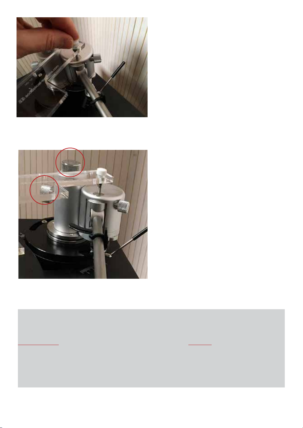
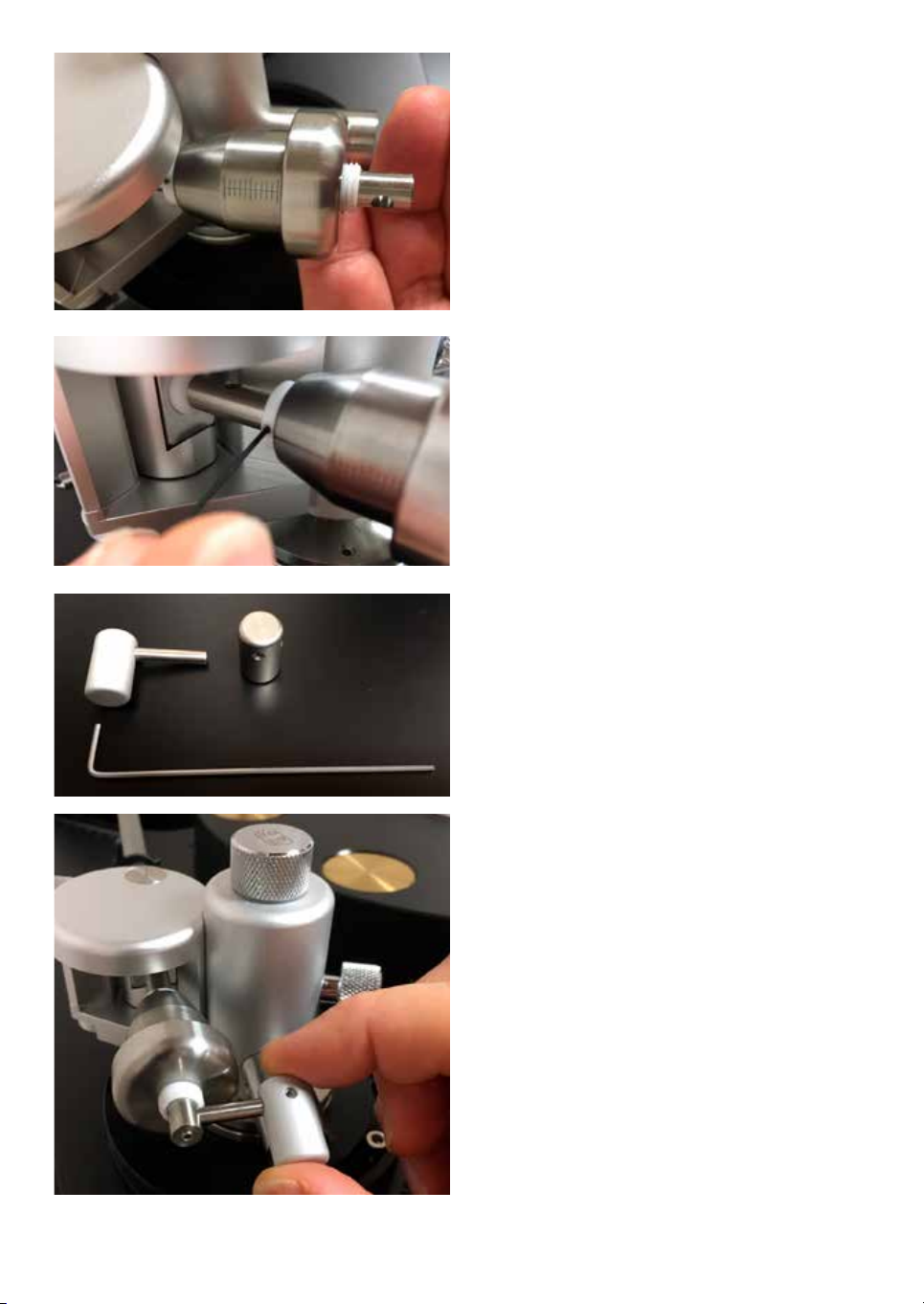
Now slide the alignment template into place
with the 8 mm hole thread at the end of its
outward positioning beam over the pivot
locating plate on the AQUILAR.
Now take the white knob ngerscrew and put it
into the 8 mm hole with the tip downwards.
The tip must meet the indention in the center of
the 12 mm pivot plate.
The AQUILAR should be positioned, so that
the underside of the armwand is approximately
2.5 cm / 1” above the turntable’s platter surface.
First you have to unlock the knob screw at
the inward side of the VTA tower by turning it
ONLY 1/4 revolutions anti-clockwise (A).
If you need to adjust for the above desired
height by lifting the AQUILAR in height above
the arm board, adjust the height using the top
VTA knob (B).
A
B
Important:
Always loose locking screw A rst (1/4 turn
only) before doing any height adjustment at
top knob B !
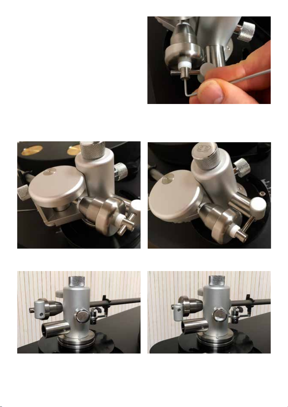
11
Before you proceed to mount the cartridge of
your choice, you rst have to attach the main
counterweight and the lateral weight assembly
to the AQUILAR.
Please remove the lateral weight assembly
as well as the airplane-nose shaped HD18
counterweight from the AQUILAR’s box.
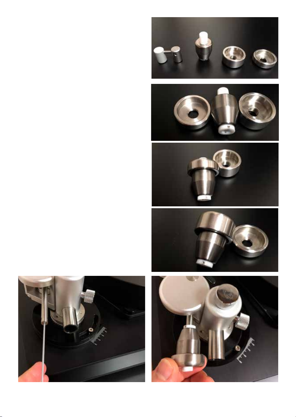
Next take the metric 1,5 Allen key and slightly
turn the screw in the counterbar’s end
anti-clockwise - only about 1-2 revolutions (1).
Now please take the HD18 counterweight and
slide it - narrow head to the front - onto the
stainless steel counterbar (2).
laretal
weights
main
conterweight
2ndary
for 12” 2ndary
for 10”
12
12
Consider a preliminary position like
pictured (1).
You may - even so slightly!! - x the PTFE-
sleeve on the counterbar attending 1 of the 2 M2
grub screws with the 0.89/90 Allen key (2).
In the next step please loosen booth lateral
weights from the 4 mm diameter stainless steel
rod (3).
Select 1 of the 2 lateral weights:
For a cartridge weight of approx.14 grams
or less, please use the aluminium cylinder
(matt silver in color and light weight).
For a cartridge body weight of 15 to 25
grams please select the stainless steel lateral
weight (higher weight).
For a cartridge weight of 26 to 31 grams,
please select the extra long rod from the
accessory box and use both lateral weights.
Such a weight is unlikely, nevertheless it can
be accomodated as described in detail later
in this manual.
Fix the aluminum (or stainless steel) cylinder
again at the end of the rod.
Now slide the rod into the inward pointing side
of the through hole in the end of the
counterbar.
This position ensures perfect lateral balance
with the geometry of the AQUILAR.
1
2
3
13
Please x the rod - with the end just meeting the
opening of the through hole - by attending again
to the M3 grub screw at the end (1).
Settings in pictures (2 + 3) and (4 + 5) are both
possible and correct.
1
2 3
4 5
14
In case you are working with an unusually
heavy cartridge weighing in at more than
25 grams, you may need to use both lateral
weights to counterbalance that cartridge.
It is unlikely, that such a cartridge is used -
however we never know what the future brings
and your AQUILAR is able to counterbalance
a wider range of cartridge weights than most
other tonearms.
Now position the aluminum lateral weight left
(outward - A) of the counterbar and the
stainless steel lateral weight right (inward - B)
onto the 4 mm rod.
The aluminum lateral weight has to be
positioned as pictured, otherwise there is no
perfect lateral balance possible. AB

15
How to mount your cartridge
of choice for best performance
Here are just some standard recommendations:
For mounting your cartridge, please use
NON- magnetic M2.5 screws and plastic
washers under the screws head. We recommend
using Titanium screws.
If you can’t use Titanium screws, please use
brass/gun metal M2.5 screws. They are non-
magnetic and provide good energy transfer.
Aluminum is too soft and does not give enough
coupling for perfect energy transfer.
Stainless steel screws always have a minimum
of magnetism - do not use them. You will loose
sound quality.
Do use, if possible, a torque driver with
precisely adjustable settings.
For M2.5 cartridge screws please use torque
settings according to 80-90% of maximum as
recommended by German engineering norm for
DIN 912.
This ensures perfect energy transfer - and
thus gives you the most dynamic and detailed,
uncolored sound from your cartridge.
Detailed recommendations regarding mounting
screws, settings and special tools are available
from acoustical-systems upon your request.
Recommended torque values for
cartridge mounting screws for
optimum energy transfer
M2.5 torque
Titanium 0.75 Nm = 75 cNm
Stainless steel 0.58 Nm = 58 cNm
Brass 0.45 Nm = 45 cNm
Aluminium 0.35 Nm = 35 cNm
Recommended top quality torque drivers
left: xed torque
middle and right: adjustable torque
Best sonic results can be obtained with the
special SMARTscrews made out of Titanium
Timet 1100 (if you are interested please ask
your dealer).
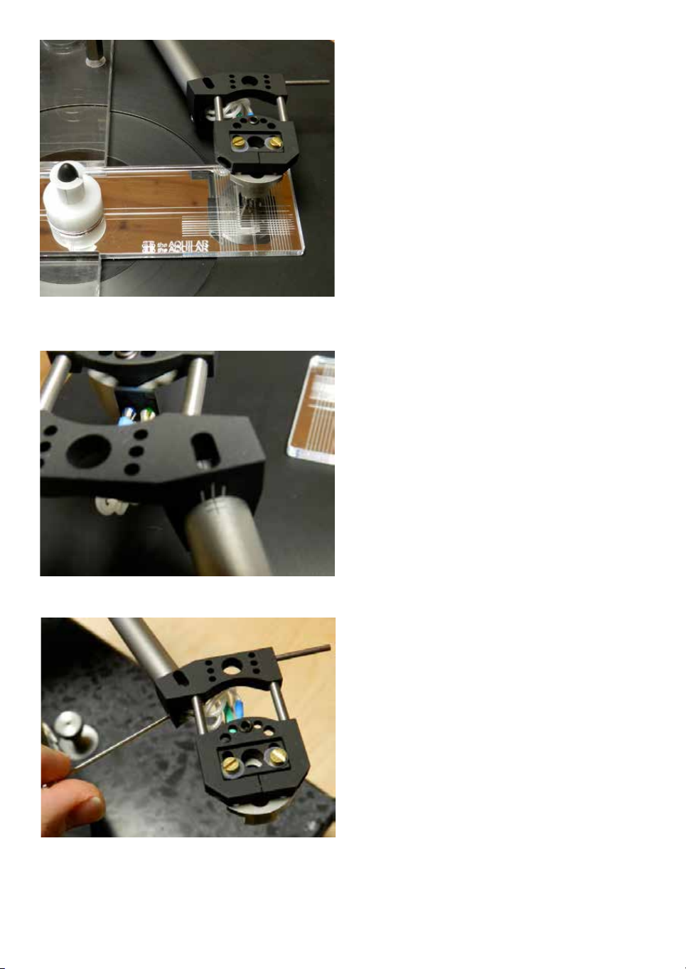
16
The AQUILAR’s mirrored alignment
template ensures a super precise 1-point
alignment to the UNI-DIN tangential curve.
The AQUILAR’s geometry is tailored to the
UNI-DIN geometry designed and introduced by
acoustical systems in 2011.
If you are interested in the background of this
all-new tangential alignment - please check back
on acoustical-systems.com website for an essay
I have written about UNI-DIN and its unique
features.
Make sure that the stylus meets the single point
sweet spot in the mirrored template while your
cartridge’s cantilever is in line with the center
line behind the sweet spot.
The template features the same precision and
construction as our SMARTractor universal
alignment tool.
Should you need to adjust azimuth, please look
at the rear collar of the AQUILAR’s headshell.
The markings will allow easy return to former
settings and give you a good indication of
direction and position.
You need to completely loosen the inward
pointing lockscrew on the left hand lower side
of the headshell’s collar, using the long silver
Allen key.
The question will come - thus I will answer
it right here: Why is the headshell lock screw
located left side for left hand operation and not
right (outward) side?
Well, why not? - Actually half the world’s
population is left handed .... as is the majority
of our staff!
Do lock the screw again after nding the right
azimuth.

17
The AQUILAR is one of only two tonearms on
the market - the other being it’s “brother” the
AXIOM - allowing you to set SRA and VTA at
the cartridge without altering static settings.
If you need to adjust SRA / VTA, rst loosen
the hidden screw on the left front side in the
AQUILAR’s headshell.
This screw actually tightens a clamp xing the
mounting plate in place.
Untighten this clamp by turning the screw
anti-clockwise for half a revolution - 180° turn
of the 1.5 Allen wrench.
Now take the 2.0 Allen key in the
accessory box for adjusting the grub screw at
the rear top end of the headshell.
Clockwise rotation will turn down the tail of the
cartridge and thus will decrease the SRA°.
The total mounting plate angle allows for freely
changing SRA for most all cartridges from 97°
down to 84°.
To accomplish this for other 10” tonearms you
would need to move them up and down their
towers by more than 2.5” up and 2.5” down -
practically impossible.
Likewise this change in SRA will of course also
inuence the VTA angle of your cantilever.
To raise the SRA° make some “room” rst by
turning the set screw up to the desired position.
Now with 1 nger carefully press the rear
bottom of your cartridge upwards.
When done, please tighten the headshell clamp
again by turning the screw clockwise.
You can use the 20 mm round scale to return
to former settings and keep track of SRA
adjustment.

18
Levelling the
AQUILAR’s pivot
Another very important feature in the
AQUILAR which is rarely found in tonearm
designs: The AQUILAR allows the precise
levelling of the horizontal pivot plane -
independent from the armboard or turntable
plinth.
This is where the 3 spikes in the upper
mounting plate come into action.
Please take the long sliver ball-head 2.0 mm
Allen key and position the small blue precision
spirit level on top of the 12 mm pivot plate.
Adjust the position of the spikes so that the
spirit level bubble is centered. The 3 spikes in
120° on a circle to each other allow for precise
levelling. Adjusting the top of the spike
clockwise makes it go down, thus lifting up that
part of the upper mounting plate and results in
the bubble moving towards that spike.
After a few moments you will get used to this
procedure and will have no problems getting
perfect level of your pivot in just 1-2 minutes.
Peek at the spirit level from directly above the
pivot by using only your dominant eye while
closing the other.
This is to make sure you have no parallax error
in your sight during this setting.
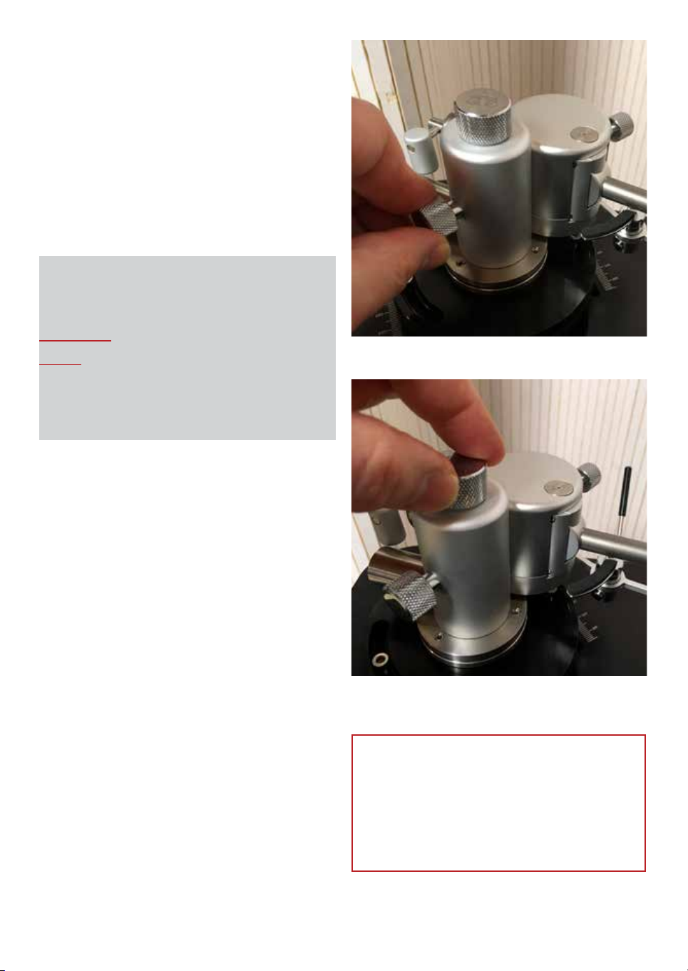
19
Raising or lowering the
AQUILAR’s pivot plane
Unscrew the lock screw on the inward
side of the VTA tower by turning it 90°
anti-clockwise.
Just a quarter of a revolution of the lock screw -
90° - is enough.
Now you can lower or lift the AQUILAR by
turning the top screw.
After you have reached the desired height,
please - gently!! - fasten the side lock screw
again.
Excessive force is never needed anywhere on
the AQUILAR. And it has absolutely no benet
whatsoever.
IMPORTANT - PLEASE NOTE
We always recommend doing all
adjustments requiring hand action
only while the stylus is lifted off the
groove.
Important:
Always loose locking screw A
rst (1/4 turn only) before
doing any height adjustment
at top knob B !
A
B
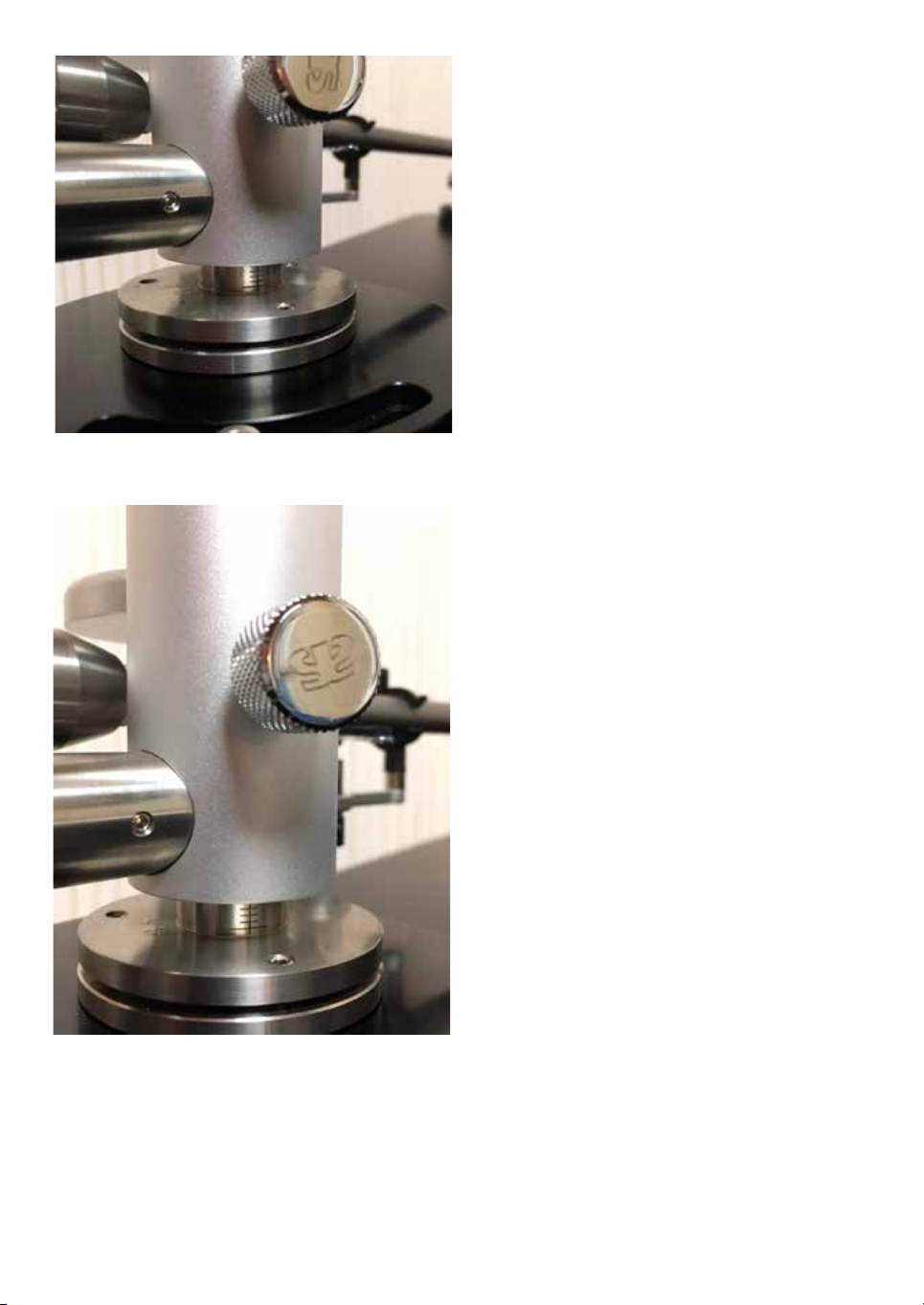
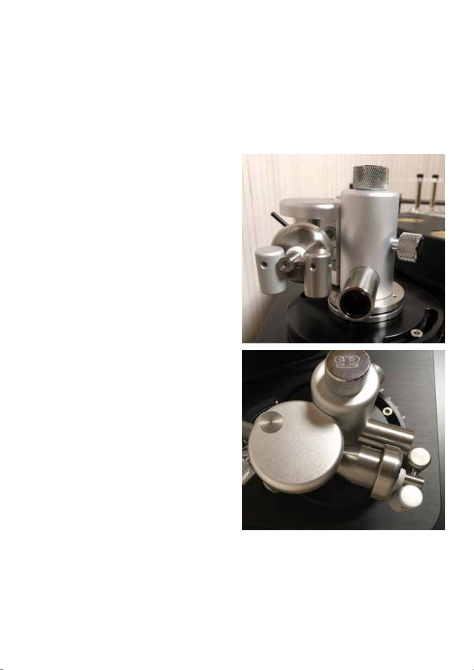
20
The AQUILAR features (2) laser engraved
height scales in its inner stainless steel pillar.
One height scale is visible from the front and
the other is visible from the inward side.
If you muse to mount the AQUILAR as a
“secondary” tonearm on a turntable featuring 2
or more armbases, know that we have specially
catered for this by providing this additional
feature of the 2nd scale on the inward pointing
side.
This manual suits for next models
2
Table of contents
Other Acoustical Systems Accessories manuals


