Component Testing Procedures
!
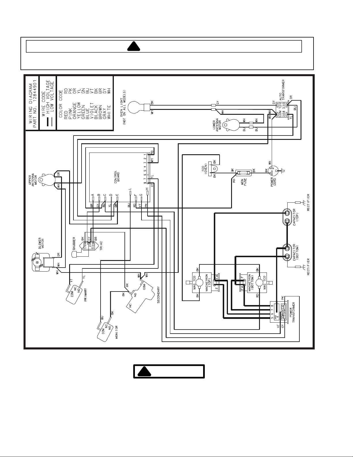
WARNING
To avoid risk of electrical shock, personal injury or death, disconnect power to oven and discharge capacitor
before servicing, unless testing requires power.
16500008 January 2009
Replaces 16027357 ©2009 ACP Inc.
2
Illustration Component Test Results
Thermal Cutout Disconnect all wires from TCO.
Measure resistance across terminals.
Cavity Thermal Fuse................................
Magnetron TCO ................................
Open at 219°F (104°C).
Open at 280°F (138°C) and
closed at 180°F (82°C).
Diode Assembly Discharge Capacitors
Remove diode lead from capacitor and
connect ohmmeter.
Reverse leads for second test.
Infinite resistance should be measured
in one direction and 50KΩor more in
the opposite direction.
NOTE: Test meter must contain a
battery of 6 volts minimum.
MT2
MT 1 GA TE
Triac Disconnect wires to triac.
Measure resistance from:
MT1 to MT2 ................................
MT1 to Gate................................
MT2 to Gate................................
All terminals to ground ................................
Caution - Do not operate oven with
wire to terminal MT2 removed.
Infinite.
Approximately 40 Ωor more.
Infinite.
Infinite.
Capacitor Discharge Capacitors
Remove wires from capacitor terminals and
connect ohmmeter, set on highest
resistance scale to terminals.
Also check between each terminal and
capacitor case.
Between Terminals: Meter should
momentarily deflect towards zero then
return to over 5 MΩ. If no deflection
occurs, or if continuous deflection
occurs, replace capacitor.
Terminal to Case: Infinite resistance.
Snubber Assembly Disconnect wires to snubber.
Measure resistance across terminals
Infinite.
Magnetron Discharge Capacitors
Remove wires from magnetron and connect
ohmmeter to terminals. Also check
between each terminal and ground.
Between Terminals: Less than 1 Ω.
Each terminal to ground measures
Infinite resistance.
NOTE: This test is not conclusive. If
oven does not heat and all other
components test good replace the
magnetron and retest.
Stirrer Motor Remove all wires from terminals.
Measure resistance from:
Terminal to terminal................................
Approximately 25 KΩ.
Blower Motor Remove all wires from motor.
Measure resistance across coil
Approximately 30 Ω.


M Service manual")