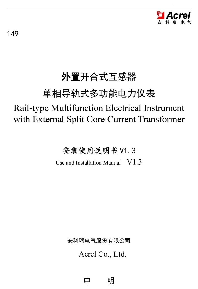
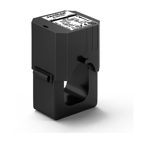
Acrel AKH-0.66L35D User manual

070
Digital Residual Current Transformer
AKH-0.66L35D
AKH-0.66L50D
AKH-0.66L70D
AKH-0.66L105D
Installation and Operation Manual V1.1
Acrel Co., Ltd.

Contents
1 Overview.................................................................................................................................... 1
2 Technical parameters.................................................................................................................. 1
3 Installation and wiring................................................................................................................2
4 Communication protocol............................................................................................................6

Acrel Co., Ltd.
1
1. Overview
Relying on the AC sampling technology, Digital Residual Current Transformer can monitor the residual
current in power distribution circuits and thus prevent electrical fires. It also supports the standard
MODBUS-RTU protocol and connects with various standard systems. Our Digital Residual Current
Transformer complies with requirements of Electrical fire monitoring system----Part 2:Residual current
electrical fire monitoring detectors, GB14287.2.
2. Technical parameters
Technical parameters Index
Input
Network 3-phase 4-wire/TN, TT system
Frequency 50Hz or 60Hz
Residual current
Rated measuring range: 10mA~3000mA
Setting range: I△n:30-1000mA, step: 1mA
Measurement accuracy class of residual current: 1.0
Communication RS485 port, MODBUS-RTU protocol
Power supply DC 24V, power consumption: ≤2VA
Safety
Power frequency withstand voltage: AC3kV/1min between the
terminal block and the housing
Insulation resistance: >100MΩ between the terminal block and
the housing
Environment
Working temperature:-10℃~+45℃;
storage temperature: -20℃~+70℃;
Relative humidity: 5%~95%, without condensation; altitude:
≤2500m

Acrel Co., Ltd.
2
3. Installation and wiring
3.1 Outline and dimensions of installation (unit: mm)
AKH-0.66L50D:
AKH-0.66L35D, AKH-0.66L50D, AKH-0.66L50D:
φ
MD
W
N
H
Dimensions
Spec&type
Overall dimensions Hole size Installation
dimensions
W H D Φ M N
L-35 106 80 32.5 35 48 51
L-70 136 110 32.5 70 66 51
L-105 176 150 32.5 105 92 51

Acrel Co., Ltd.
3
3.2 Mode of installation
Digital Residual Current Transformer is rail-mounted or fixed.
3.3 Connection mode
3.3.1 Primary side connection
L1
L2
L3
ARCM
N
TN
TNS
N
L1
L2
L3
ARCM
N
PE
L1
L2
L3
ARCM
N
PE
TNC
L1
L2
L3
ARCM
PEN
L1
L2
L3
ARCM
PEN
单相负载
TN-C-S
L1
L2
L3
ARCM
PE
N
L1
L2
L3
ARCM
N
PE
单相负载
单相负载
单相负载
负载 负载
负载 负载
负载 负载
负载 负载
相别
接线图
接地方式
TT
三相三线
L1
L2
L3
ARCM
三相四线
Note: The symbol in the table indicates a residual current transformer. It is necessary to distinguish
the wire N from the wire PE during the installation of residual current transformer. Wire N in a 4-wire system
must be connected with the residual current transformer. Such wire N must not be used as wire PE. Wire PE
must not be connected with a residual current transformer. For a TNC system, it is required to modify the
system into a partial TT system or a TN-C-S system and then connect wires as illustrated above.
3-phase 3-wire3-phase 4-wire
Load Load
Load
Load
Load Load
Load
Load
S
ingle-phase
load
S
ingle-phase
load
S
ingle-phase
load
S
ingle-phase
load
W
i
ring
diagram
P
hase
C
onnection
mode

Acrel Co., Ltd.
4
3.3.2 Secondary side connection
AKH-0.66L50D:
Example of Communication Connection
1 2 3 4
DC24V RS485
+ - A+ B-
AKH-0.66L35D、AKH-0.66L50D、AKH-0.66L50D:
Example of Communication Connection
Address Parameter R/W Value range Data type
0000H 1st-circuit residual
current R 0~3000 mA Word
0001H~0007H Reserved Word
Correct connection mode:Communication cable shielding layer is connectea with ground.
Upoer computer
Two-core shielded line/shielding
layer is connected with ground.
Correct connection mode:Communication cable shielding layer is connectea with ground.
Two-core shielded line/shielding
layer is connected with ground.
Upoer computer

Acrel Co., Ltd.
5
0008H 1st-circuit actuation
current R 30~1000 mA (OFF) Word
0009H~000FH Reserved Word
0010H 1st-circuit delay time R 0.1S~60.0S Word
0011H~0017H Reserved Word
0018H Communication
address R 1~247 Word
0019H Communication baud
rate R
1, 2, 3 and 4 indicate 4.800、
9.600、
19.20、38.40 kbps respectively
with 9.600 kbps by default
Word
001AH Alarm status R Refer to the attached data analysis
table for details Word
001BH Remote alarm
clearing R/W
An alarm can be cleared remotely
if 0x1234 is written. Return to zero
automatically after the alarm is
cleared successfully (resolve the
fault in advance).
Word
001CH 001DH Reserved Word
001EH Year R/W 00-99 indicates 2000-2099 Word
Month R/W 1-12
001FH Day R/W 1-31 Word
Hour R/W 0-59
0020H Minute R/W 0-59 Word
Second R/W 0-59
0021H Software version R For example, 10 indicates the
version V1.0. Word
0022H~002BH Reserved Word
002CH
Event
record
0
Event type R Type 1: residual current
Type 2: temperature
Word
Event
channel R
Current channels 1, 2, 3, 4
correspond to circuits 1, 2, 3, 4
Temperature channels 2, 3, 4
correspond to temperatures at
phases A, B, C.
002DH Alarm
setting R
For the residual current type, the
unit is mA
For the temperature type, the unit
is ℃.
Word
002EH Actual alarm
value R
For the residual current type, the
unit is mA
For the temperature type, the unit
is ℃.
Word
002FH Year R Alarm time, year Word
Month R Alarm time, month
0030H Day R Alarm time, day Word
Hour R Alarm time, hour
Note: The power supply is an isolated 24VDC power source. Make sure that the input voltage of

Acrel Co., Ltd.
6
transformer is not below 18V. If the input voltage is below 18V, it is necessary to apply an auxiliary power
source near the existing power source and keep these power sources separated in connnection. The shielded
twisted pair or 4-core shielded wire are preferred for communication connection (consistent with the power
connection). The minimum wire diameter is 0.75mm2. The shielding layer is connected with ground. The
communication connection must be far away from the power cable or other strong electric field. If the wire
routing is longer than 100m, it is preferred to configure an appropriate resistor (recommended 120Ω) between
A+ and B- of the last transformer.
4. Communication protocol
Modbus-RTU communication protocol is followed. The table below lists communication addresses.
Attachment:
0031H Minute R Alarm time, minute Word
Second R Alarm time, second
0032H~0067H Rest 9 alarm entries are saved here in the rule and format same as above Word
Bit1 Bit0 Status
0 0 Normal
0 1 Early
warning
1 0 Alarm
1 1 Reserved

Acrel Co., Ltd.
Headquarters: Acrel Co., LTD.
Address: No.253 Yulv Road Jiading District, Shanghai,China
TEL.: 0086-21-69158338 0086-21-69156052 0086-21-59156392 0086-21-69156971
Fax: 0086-21-69158303
Web-site: www.acrel-electric.com
E-mail: [email protected]
Postcode: 201801
Manufacturer: Jiangsu Acrel Electrical Manufacturing Co., LTD.
Address: No.5 Dongmeng Road,Dongmeng industrial Park, Nanzha Street,Jiangyin City,Jiangsu
Province,China
TEL./Fax: 0086-510-86179970
Web-site: www.jsacrel.com
Postcode: 214405
E-mail: [email protected]
This manual suits for next models
3
Table of contents
Other Acrel Transformer manuals
Popular Transformer manuals by other brands

HEINE
HEINE EN50 manual

weschler instruments
weschler instruments Advantage II Enhanced Series owner's manual

Audio Note
Audio Note AN-S8 Owner's Information

Edisons
Edisons ST-100W instruction manual

Omicron Lab
Omicron Lab B-WIT 100 user manual

Heitronic
Heitronic 20086 Installation and operating instructions