manuals.online logo
Brands
  1. Home
  2. •
  3. Brands
  4. •
  5. Lionel
  6. •
  7. Transformer
  8. •
  9. Lionel ZW User manual

Lionel ZW User manual

INSTRUCTIONS
LIONEL TYPE ZW TRANSFORMER
115 VOLTS 6 CYCLES 275 WATTS
ALTERNATING CURRENT ONLY
INTRODUCTION
Lionel electric trains operate on low voltage, ranging from 8 to 18
volts. Lionel Transformers reduce or transform the available house volt-
age to the low voltage required. The pl ug at the end of the transformer
cord is plugged into any convenient wall outlet of 115 volts, 60 cycles
alternating. current. The low voltage for operating trains and accessories
is then obtained from the output terminals at the rear of the transformer.
The wattage rating of the
H
ZW Transformer is' 275 watts. The
wattage of a transformer is a measure of its capacity or ability to furnish
power. The wattage of the transformer you need is governed by the kind
and number of trains and the number of lights and operating accessories
in your model railroad system. The larger the train and the greater the
number of accessories, the more power you need and the higher should be
the wattage rating of the transformer.
Page
USES OF TRANSFORMER CONTROL~
ZW Transformers are so designed that two trains can be operated
and controlled independently of each other on a properly designed layout.
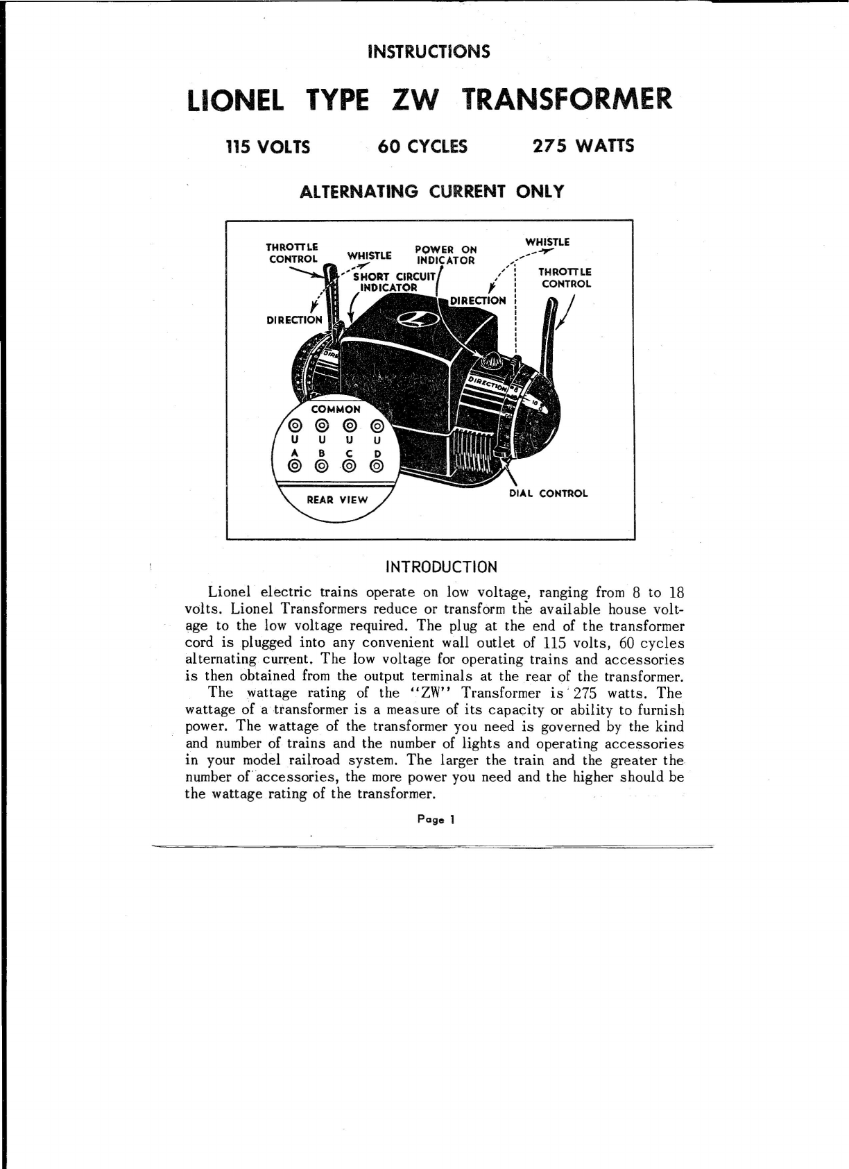
On each end of the transformer there is a long throttle-type lever. This is
the speed control. By moving this throttle you can regulate the voltage
supplied to the track so that the train speed can be regulated in a realistic
fashion. In Figure 2 the left-hand throttle controls the voltage supplied by
the output binding posts labeled A-U . while the right-hand throttle con-
trols the pair labeled D_U
It•
Next to each of the throttles you will find a short lever. This is a
combination whistle and reversing control for that circuit. Moving the
lever away from you, toward the side marked Whistle , blows the train
whistle. Moving the lever toward you, to the side marked Direction .
stopsv.starts and reverses the locomotive. A separate whistle and reverse
lever is provided for each of the two throttle-eon trolled train circuits so
that if you operate two trains on separate sections of your model railroad
you can sound each whistle separately and start and stop each locomotive
without interfering with the action of the other.
CONNECTING TRANSFORMER TO TRACK
••ZW Muti-Control Transformers have four pairs of binding posts
located on the rear wall of the transformer case. Each pair of these posts
provides a separate power source which can be controlled independently
of the other three. Of these the A-U and the D-U combinations are
controlled by the throttles as described above and should be used for the
main track supply. The two center combinations, B-U and C-U , are
reserved for accessories as described in a later section.
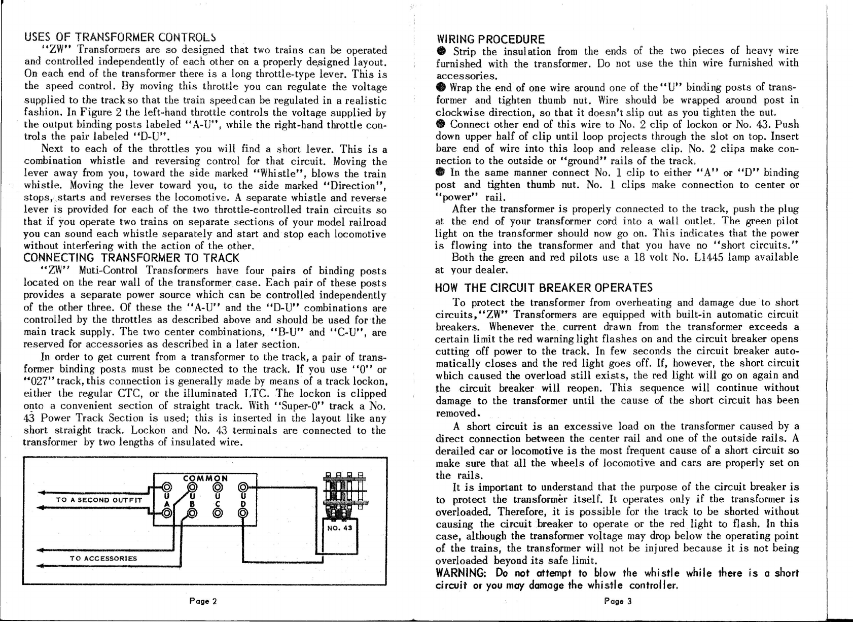
In order to get current from a transformer to the track, a pair of trans-
former binding posts must be connected to the track. If you use 0 or
'027
track, this connection is generally made by means of a track lockon,
either the regular GrC, or the illuminated LTC. The lockon is clipped
onto a convenient section of straight track. With Super-O track a No.
43 Power Track Section is used; this is inserted in the layout like any
short strai ght track. Lockon and No. 43 termi nals are connected to the
transformer by two lengths of insulated wire.
TO A SECOND OUTFIT
NO 43
TO ACCESSORIES
Page 2
WIRING PROCEDURE
• Strip the insulation from the ends of the two pieces of heavy wire
furnished with the transformer. Do not use the thin wire furnished with
accessories.
• Wrap the end of one wire around one of the U binding posts of trans-
former and tighten thumb nut. Wire should be wrapped around post in
clockwise direction, so that it doesn't slip out as you tighten the nut.
e
Connect other end of this wire to No. 2 clip of lockon or No. 43. Push
down upper half of clip until loop projects through the slot on top. Insert
bare end of wire into this loop and release clip. No. 2 clips make con-
nection to the outside or ••ground rails of the track.
• In the same manner connect No. 1 clip to either ••A or D binding
post and tighten thumb nut. No. 1 clips make connection to center or
II
power rail.
After the transformer is properly connected to the track, push the plug
at the end of your transformer cord into a wall outlet. The green pilot
light on the transformer should now go on. This indicates that the power
is flowing into the transformer and that you have no short circuits.
Both the green and red pilots use a 18 volt No. L1445 lamp available
at your dealer .
HOW THE CIRCUIT BREAKER OPERATES
To protect the transformer from overheating and damage due to short
circuits. ZW Transformers are equipped with built-in automatic circuit
breakers. Whenever the current drawn from the transformer exceeds a
certain limit the red warning light flashes on and the circuit breaker opens
cutting off power to the track. In few seconds the circuit breaker auto-
matically closes and the red light goes off. If. however, the short circuit
which caused the overload still exists, the red light will go on again and
the circuit breaker will reopen. This sequence will continue without
damage to the transformer until t.he cause of the short circuit has been
removed.
A short circuit is an excessive load on the transformer caused by a
direct connection between the center rail and one of the outside rails. A
derailed car or locomotive is the most frequent cause of a short circuit so
make sure that all the wheels of locomotive and cars are properly set on
the rails.
It is important to understand that the purpose of the circuit breaker is
to protect the transformer itself. It operates only if the transformer is
overloaded. Therefore, it is possible for the track to be shorted without
causing the circuitBreaker to operate or the red light to flash. In this
case, although the transformer voltage may drop below the operating point
of the trains, the transformer will not be inj ured because it is not being
overloaded beyond its safe limit.
WARNING: Do not attempt to blow the whistle while there is a short
circuit or you may damage the whistle controller.
Page 3
HOW TO CONNECT ACCESSORI ES
While transformer binding posts A-U and D-U are reserved for
train control, B-U and
C-U
are intend~d to supply power for lights,
switches and other accessory equipment. The voltage supplied by these
two combinations is regulated by the two dials located next to the throttle
controls and may be set to any figure indicated on the dial. Most ill umi-
nated accessories operate on 12-14 volts, while operating accessories
work on voltage ranging from 10 to 16 volts depending on the accessory.
To determine the proper voltage for your
accessories, connect the accessory terminals
to
uB_U
or
C-U
posts of your trans-
former and slowly move the corresponding
dial control from OFF to the point where
you get the desired brightness of illumination
or satifactory operation of the mechanism.
Be careful,particularlyin the case of illumi-
nated accessories, not to set the voltage
too high, or you will burn out the lamps. If
you operate with the lowest voltage possible
you will greatly extend the life ofyour lamps
and other equipment. In the event that you
have several accessories requiring the same
voltage it is possible to use the same trans-
former binding posts for
.all,
A simple method
for wiring a number of lights, etc. in parallel
is shown below.
How to Read Voltage.
Top
line indicates Dial Voltage;
Bottom Iins Throttle Voltage.
NO. 76
NO. 195
,~
Page 4
HOWTO OPERATE A TYPICAL TWO-TRAIN LAYOUT
37
260
ZW-TRANSFORMER
OFF-ON
SWITCHES
Illustration shows a Super-O layout for running two trains independent-
ly. In order to operate two trains in this manner, the layout must be
••sectionalized , that is one loop insulated from the other loop by insu-
lators at each of the points indicated by dots. Each loop is controlled by
a separate throttle lever, while the accessory binding posts are used for
switches and other accessories which may be in the railroad system. For
convenience all controllers should be mounted on a centrally located
panel board. Two No. 37 Uncoupling Units are also shown in the layout
but No. 36 Operating Blades can be inserted in any straight track.
NOTE: As shown in the diagram, only one No. 43 Power track section is
employed. Connections to insulated power rail sections are made with No.
62 Power Track Lockons, available from your dealer. In large and compli-
cated layouts such as this, additional No. 61 Ground Lockons may be
necessary for good ground throughout the system.
In the lower right hand corner of the diagram are shown two electrical
toggle or knife switches. The purpose of the right toggle switch is to cut
the current in or out of the siding. The other switch sectionalizes the
Page 5
left half of the outside loop while a second train crosses over from the
inside, loop to the right half of the outside loop.
OPERATING ADDITIONAL TRAINS
Since ••ZW Transformers have four independently variable circuits,
as many as four trains can be operated independently of each other with
a proper layout. However, in order to control the whistles and direction of
the two additional trains, external No. 167 Whistle Controllers have to be
added to the B-U and C-U circuits.
REPLACEMENT LAMPS
Both the green and red pilots use an 18 volt No. L1445 lamp available
at
YOo/
dealer. To replace lamps, unscrew the red or green lens.
I
- I
I
i.'1
'II,,
I
j
I
LIONEL WARRANTY
All Lionel model railroad equipment is carefully made and in-
spected and is guaranteed against defects in materials or in our
workmanship. If any such defects develop, we will repair or re-
place the defective part or parts, without charge, within one year
of the date purchased. If in the future this equipment should ever
require servicing, you may either send it to the Factory Service
Department or take it to your nearest Lionel Approved Service
Station.
'~"'~"'-'-
The LIONEL OORPORATION
SERVICE DEPARTMENT: Hoffman Place,-Hillside( N.J.
Printed in V.S. of America Model (R) ZW-251 1/61
Page 6

Other Lionel Transformer manuals

Lionel GW-180 User manual

Lionel

Lionel GW-180 User manual

Lionel CW-80 Transformer User manual

Lionel

Lionel CW-80 Transformer User manual

Lionel GW-180 User manual

Lionel

Lionel GW-180 User manual

Popular Transformer manuals by other brands

RCD 40103/202/3/5/10 Operating & safety guide

RCD

RCD 40103/202/3/5/10 Operating & safety guide

Palmer PMT02 manual

Palmer

Palmer PMT02 manual

Lovato DM TA Series quick guide

Lovato

Lovato DM TA Series quick guide

janitza CTB Series User Manual and Mounting Instructions

janitza

janitza CTB Series User Manual and Mounting Instructions

Titanium TT-DR-CVB-100 manual

Titanium

Titanium TT-DR-CVB-100 manual

Monacor PATL-100/XC quick start guide

Monacor

Monacor PATL-100/XC quick start guide

Superior Electric POWERSTAT POWERKOTE 21 Series Instructions for installation, operation and maintenance

Superior Electric

Superior Electric POWERSTAT POWERKOTE 21 Series Instructions for installation, operation and maintenance

SSS Siedle TR 603-0 Product information

SSS Siedle

SSS Siedle TR 603-0 Product information

Anslut 008469 operating instructions

Anslut

Anslut 008469 operating instructions

Monacor FGA-22 manual

Monacor

Monacor FGA-22 manual

MEISHILE DT-100VAC user manual

MEISHILE

MEISHILE DT-100VAC user manual

Audioplex STEREO MATCHIT 200 installation manual

Audioplex

Audioplex STEREO MATCHIT 200 installation manual

WAC Lighting InvisiLED EN-OD24100-RB2-T Installation instruction

WAC Lighting

WAC Lighting InvisiLED EN-OD24100-RB2-T Installation instruction

VOLTCRAFT AT-400 operating instructions

VOLTCRAFT

VOLTCRAFT AT-400 operating instructions

Altec Lansing 15550A TRANSFORMERS manual

Altec Lansing

Altec Lansing 15550A TRANSFORMERS manual

RCF IT 4000 manual

RCF

RCF IT 4000 manual

Arteche KA user manual

Arteche

Arteche KA user manual

Griven AL3350 instruction manual

Griven

Griven AL3350 instruction manual

manuals.online logo
manuals.online logoBrands
  • About & Mission
  • Contact us
  • Privacy Policy
  • Terms and Conditions

Copyright 2025 Manuals.Online. All Rights Reserved.