manuals.online logo
Brands
  1. Home
  2. •
  3. Brands
  4. •
  5. Monacor
  6. •
  7. Transformer
  8. •
  9. Monacor PATL-100/XC User manual

Monacor PATL-100/XC User manual

ELECTRONICS FOR SPECIALISTS ELECTRONICS FOR SPECIALISTS ELECTRONICS FOR SPECIALISTS ELECTRONICS FOR SPECIALISTS ELECTRONICS FOR SPECIALISTS ELECTRONICS
PATL-100/XC
Bestell-Nr. • Order No. 1000092
MONACOR INTERNATIONAL GmbH & Co. KG • Zum Falsch 36 • 28307 Bremen • Germany
Copyright©by MONACOR INTERNATIONAL. All rights reserved. A-2062.99.01.05.2020
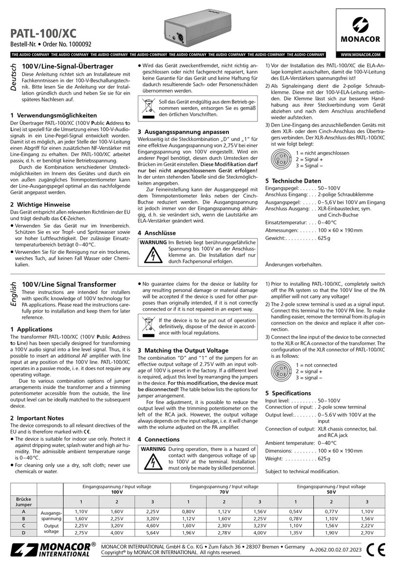
100V/Line Signal Transformer
These instructions are intended for installers
with sufficient knowledge of 100V technology
for PAapplications. Please read the instructions
carefully prior to installation and keep them for
later reference.
1 Applications
The transformer PATL-100/XC (100V Public Address
to Line) has been specially designed for transforming
a 100V audio signal into a line level signal. Thus, it is
possible to insert an additional AF amplifier with line
input at any position of the 100V line. PATL-100/XC
operates in a passive mode, i.e. it does not require any
operating voltage.
Due to various combination options of jumper
arrangements inside the transformer and a trimming
potentiometer accessible from the outside, the line out-
put level can be ideally matched to the subsequent unit.
2 Safety Notes
The unit corresponds to all relevant directives of the EU
and is therefore marked with .
•
The unit is suitable for indoor use only. Protect it
against dripping water, splash water and high air
humidity. The admissible ambient temperature
range is 0– 40°C.
•
For cleaning only use a dry, soft cloth; never use
chemicals or water.
•
No guarantee claims for the unit or liability for any
resulting personal damage or material damage will
be accepted if the unit is used for other purposes
than originally intended, if it is not correctly con-
nected or if it is not repaired in an expert way.
If the unit is to be put out of operation
definitely, dispose of the unit in accordance
with local regulations.
3 Matching the Output Voltage
The combination “A” and “2” of the jumpers for an
effective output voltage of 1.6V at an input voltage
of 100V is preset in the factory. If a different level is
required, adjust this level by rearranging the jumpers
in the unit. For this modification, the unit must
be disconnected! The table below lists the possible
options.
For fine adjustment, it is possible to reduce the
output level with the trimming potentiometer on the
left of the RCA jack. However, the output voltage
always depends on the input voltage, i.e. it will change
with the volume adjusted on the PA amplifier.
4 Connections
WARNING During operation, there is a hazard of
contact with dangerous voltage of up
to 100V at the terminal.
Installation must only be made by
skilled personnel.
1) Prior to installing PATL-100/XC, completely switch
off the PA system so that the 100 V speaker cable of
the PA amplifier will not carry any voltage!
2) The 2-pole screw terminal is used as a signal input.
Connect this terminal to the 100V PA line. To
make handling easier, remove the terminal from its
plug-in connection on the unit and replace it after
connection.
3) Connect the line input of the unit to be connected
to the XLR or RCA connector of the transformer.
The configuration of the XLR chassis connector of
PATL-100/XC is as follows:
1
23
1 = not connected
2 = signal +
3 = signal −
5 Specifications
Input level: . . . . . . . . .50–100 V
Connection of input:
. .2-pole screw terminal
Output level:. . . . . . . .0 –5.6V
at 100V at the input
Connection of output: XLR chassis connector, bal.
and RCA jack
Ambient temperature: 0–40 °C
Dimensions: . . . . . . . .100 × 60 × 190 mm
Weight: . . . . . . . . . . .500 g
Subject to technical modification.
100V/Line-Signal-Übertrager
Diese Anleitung richtet sich an Installateure mit
Fachkenntnissen in der 100-V-Beschallungstech-
nik. Bitte lesen Sie die Anleitung vor der Instal-
lation gründlich durch und heben Sie sie für ein
späteres Nachlesen auf.
1 Verwendungsmöglichkeiten
Der Übertrager PATL-100/XC (100V Public Address to
Line) ist speziell für die Umsetzung eines 100-V-Audio-
signals in ein Line-Pegel-Signal entwickelt worden.
Damit ist es möglich, an jeder Stelle der 100-V-Leitung
einen Abgriff für einen zusätzlichen NF-Verstärker mit
Line-Eingang zu erhalten. Der PATL-100/XC arbeitet
passiv, d.h. er benötigt keine Betriebsspannung.
Durch die Kombination verschiedener Umsteck-
möglichkeiten im Innern des Gerätes und durch ein
von außen zugängliches Trimmpotentiometer kann der
Line-Ausgangspegel an das nachfolgende Gerät opti-
mal angepasst werden.
2 Sicherheitshinweise
Das Gerät entspricht allen relevanten Richtlinien der EU
und trägt deshalb das -Zeichen.
•
Verwenden Sie das Gerät nur im Innenbereich.
Schützen Sie es vor Tropf- und Spritzwasser sowie
vor hoher Luftfeuchtigkeit. Der zulässige Einsatz-
temperaturbereich beträgt 0–40 °C.
•
Verwenden Sie zum Reinigen nur ein trockenes, wei-
ches Tuch, niemals Wasser oder Chemikalien.
•
Wird das Gerät zweckentfremdet, falsch ange-
schlossen oder nicht fachgerecht repariert, kann
keine Garantie für das Gerät und keine Haftung für
dadurch resultierende Sach- oder Personenschäden
übernommen werden.
Soll das Gerät endgültig aus dem Betrieb ge-
nommen werden, entsorgen Sie es gemäß
den örtlichen Vorschriften.
3 Ausgangsspannung anpassen
Werksseitig ist die Steckkombination „A“ und „2“ für
eine effektive Ausgangsspannung von 1,6V bei einer
Eingangsspannung von 100V eingestellt. Wird ein
anderer Pegel benötigt, diesen durch Umstecken der
Brücken im Gerät einstellen. Diese Modifikation darf
nur bei nicht angeschlossenem Gerät erfolgen! In
der unten stehenden Tabelle sind die Steckmöglichkei-
ten angegeben.
Zur Feineinstellung kann der Ausgangspegel mit
dem Trimmpotentiometer links neben der Cinch-
Buchse reduziert werden. Die Ausgangsspannung
ist jedoch immer von der Eingangsspannung abhän-
gig, d.h. sie verändert sich, wenn die Lautstärke am
ELA-Verstärker geändert wird.
4 Anschlüsse
WARNUNG Im Betrieb liegt berührungsgefährli-
che Spannung bis 100V an der An-
schlussklemme an.
Die Installation darf nur durch Fach-
personal erfolgen.
1) Vor der Installation des PATL-100/XC die ELA-An-
lage komplett ausschalten, damit die 100-V-Laut-
sprecherleitung des ELA-Verstärkers spannungsfrei
ist!
2) Als Signaleingang dient die 2-polige Schraub-
klemme. Diese mit der 100-V-ELA-Leitung verbin-
den. Die Klemme lässt sich zur besseren Hand-
habung aus ihrer Steckverbindung vom Gerät
abziehen und nach dem Anschluss anschließend
wieder aufstecken.
3) Den Line-Eingang des anzuschließenden Gerätes
mit dem XLR- oder dem Cinch-Anschluss des Über-
tragers verbinden. Der XLR-Einbaustecker des PATL-
100/XC ist wie folgt belegt:
1
23
1 = nicht angeschlossen
2 = Signal +
3 = Signal −
5 Technische Daten
Eingangspegel: . . . . . .50 –100V
Anschluss Eingang: . . .2-polige Schraubklemme
Ausgangspegel: . . . . .0 –5,6V bei 100 V
am Eingang
Anschluss Ausgang: . .XLR-Einbaustecker, sym.
und Cinch-Buchse
Einsatztemperatur: . . .0 –40°C
Abmessungen: . . . . . .100 × 60 × 190mm
Gewicht:. . . . . . . . . . .500 g
Änderungen vorbehalten.
DeutschEnglish
Eingangsspannung / Input voltage
100V
Eingangsspannung / Input voltage
70V
Eingangsspannung / Input voltage
50V
Brücke
Jumper 123123123
AAusgangs-
spannung
Output
voltage
1,10V 1,60V 2,25 V 0,80 V 1,12 V 1,56 V 0,54 V 0,77V 1,10 V
B1,60V 2,25V 3,20 V 1,12 V 1,60 V 2,25 V 0,78 V 1,10V 1,56 V
C2,25V 3,20V 4,60 V 1,60 V 2,30 V 3,23 V 1,10 V 1,56V 2,22 V
D2,75V 4,00V 5,64 V 1,96 V 2,78 V 4,00 V 1,35 V 1,90V 2,70 V
ELECTRONICS FOR SPECIALISTS ELECTRONICS FOR SPECIALISTS ELECTRONICS FOR SPECIALISTS ELECTRONICS FOR SPECIALISTS ELECTRONICS FOR SPECIALISTS ELECTRONICS
MONACOR INTERNATIONAL GmbH & Co. KG • Zum Falsch 36 • 28307 Bremen • Germany
Copyright©by MONACOR INTERNATIONAL. All rights reserved. A-2062.99.01.05.2020
Trasformatore segnale 100V/Line
Queste istruzioni sono rivolte agli installatori che
possiedono delle conoscenze specifiche suffi-
cienti della tecnica di sonorizzazione a 100V. Vi
preghiamo di leggerle attentamente prima dell‘in-
stallazione e di conservarle per un uso futuro.
1 Possibilità d’impiego
Il trasformatore PATL-100/XC (100 V Public Address
to Line) è stato realizzato per trasformare un segnale
audio 100V in un segnale con livello Line. Così è pos-
sibile inserire in un qualsiasi punto del circuito 100 V un
amplificatore supplementare a bassa frequenza con in-
gresso Line. Il PATL-100/XC è a funzionamento passivo
e pertanto non richiedo nessuna tensione d’esercizio.
Grazie alle diversi combinazioni possibili realizza-
bili all’interno dell’apparecchio e a un potenziometro
accessibile dall’esterno, il livello d’uscita Line può es-
sere adattato in modo ottimale all’apparecchio a valle.
2 Avvertenze di sicurrezza
Quest’apparecchio è conforme a tutte le direttive rile-
vanti dell’UE e pertanto porta la sigla .
•
Usare l’apparecchio solo all’interno di locali. Proteg-
gerlo dall’acqua gocciolante e dagli spruzzi d’acqua
nonché da alta umidità dell’aria. La temperatura
d’esercizio ammessa è 0–40°C.
•
Per la pulizia usare solo un panno morbido, asciutto;
non impiegare in nessun caso prodotti chimici o
acqua.
•
Nel caso d’uso improprio, di collegamenti sbagliati o
di riparazione non a regola d’arte cessa ogni diritto
di garanzia e non si assume nessuna responsabilità
per eventuali danni a persone o a cose.
Se si desidera eliminare l’apparecchio defini-
tivamente, consegnarlo per lo smaltimento
ad un’istituzione locale per il riciclaggio.
3 Adattare la tensione d’uscita
Dalla fabbrica è impostata la combinazione “A” e “2”
per offrire una tensione effettiva d’uscita di 1,6V con
tensione d’ingresso di 100V. Se è richiesto un altro
livello, lo si ottiene spostando i ponticelli all’interno
dell’apparecchio. Tale modifica deve essere ese-
guita solo con l’apparecchio staccato! La tabella
sottostante mostra le varie possibilità di combinazioni.
Per una regolazione fine ci si può servire del po-
tenziometro a sinistra della presa RCA. La tensione
d’uscita dipende comunque sempre dalla tensione
d’ingresso, cioè cambia se il volume dell’amplificatore
PA viene modificato.
4 Collegamenti
ATTENZIONE Durante il funzionamento, al morsetto
di collegamento è presente una ten-
sione fino a 100V pericolosa in caso
di contatto.
L’installazione deve essere fatta solo da
personale qualificato.
1) Prima dell’installazione del PATL-100/XC, spegnere
completamente l’impianto PA in modo che la linea
audio di 100V sia senza tensione!
2) Il morsetto a vite a 2 poli serve da ingresso per il
segnale. Collegarlo con la linea PA 100V. Per mag-
giore comodità, il morsetto può essere sfilato dal
suo connettore e rimesso dopo il collegamento.
3) Collegare l’ingresso Line dell’apparecchio da col-
legare con il connettore XLR o RCA del trasfor-
matore. I contatti della spina da pannello XLR del
PATL-100/XC sono i seguenti:
1
23
1 = libero
2 = segnale +
3 = segnale −
5 Dati tecnici
Livello d’ingresso: . . . .50 –100 V
Contatti ingresso: . . . .morsetto a vite a 2 poli
Livello d’uscita: . . . . . .0 –5,6V con 100V
all’ingresso
Contatti uscita: . . . . . .spina da pannello XLR,
simm. e presa RCA
Temperatura
d’esercizio: . . . . . . . . .0– 40°C
Dimensioni:. . . . . . . . .100 × 60 × 190 mm
Peso:. . . . . . . . . . . . . .500 g
Con riserva di modifiche tecniche.
PATL-100/XC
Référence num. • Codice 1000092
Transformateur signal ligne 100V
Cette notice s’adresse aux installateurs possédant
des connaissances suffisantes en technique de
sonorisation ligne 100V. Veuillez lire la présente
notice avec attention avant l‘installation et conser-
vez-la pour pouvoir vous y reporter ultérieurement.
1 Possibilités d’utilisation
Le transformateur PATL-100/XC (100V Public Address
to Line) est spécialement conçu pour transformer un
signal audio 100V en un signal niveau Ligne. Il est ainsi
possible, à n’importe quel endroit de la ligne 100V,
d’obtenir un accès pour repiquer le signal pour un
amplificateur basse fréquence supplémentaire avec
entrée Ligne. Le PATL-100/XC fonctionne en mode
passif, c’est-à-dire qu’il ne nécessite aucune tension
de fonctionnement.
En combinant diverses possibilités de placement de
cavaliers dans l’appareil et par un potentiomètre trimmer
accessible de l’extérieur, le niveau de sortie Ligne peut
être adapté de manière optimale à l’appareil suivant.
2 Conseils de sécurité
L’appareil répond à toutes les directives nécessaires de
l’Union européenne et porte donc le symbole .
•
L’appareil n’est conçu que pour une utilisation en
intérieur. Protégez-le de tout type de projections
d’eau, des éclaboussures et d’une humidité d‘air
élevée. La plage de température ambiante admis-
sible est de 0– 40°C.
• Pour le nettoyage, utilisez uniquement un chiffon sec
et doux, en aucun cas de produits chimiques ou d’eau.
• Nous déclinons toute responsabilité en cas de dom-
mages matériels ou corporels résultants si
l’appareil
est utilisé dans un but autre que celui pour lequel il a
été conçu, s’il n’est pas correctement branché ou s’il
n’est pas reparé par une personne habilitée; en outre,
la garantie deviendrait caduque.
Lorsque l’appareil est définitivement retiré
du service, vous devez l‘éliminer conformé-
ment aux directives locales.
CARTONS ET EMBALLAGE
PAPIER À TRIER
3 Adaptation de la tension de sortie
A l’usine, la combinaison «A» et «2» des cavaliers
pour une tension de sortie effective de 1,6V à une
tension d’entrée de 100V est préréglée. Si un autre
niveau est nécessaire, réglez-le en modifiant les cava-
liers dans l’appareil. Cette modification ne doit être
effectuée que lorsque l’appareil est déconnecté
du secteur! Le tableau ci-dessous présente les possi-
bilités de positionnement.
Pour un réglage précis, il est possible de diminuer
le niveau de sortie avec le potentiomètre trimmer à
gauche de la prise RCA. Cependant, la tension de sor-
tie dépend toujours de la tension d’entrée, c’est-à-dire
elle se modifie lorsque le volume est modifié sur l’am-
plificateur Public Adress.
4 Branchements
ATTENTION Pendant le fonctionnement, une ten-
sion dangereuse de 100V maximum est
présente à la borne de branchement.
Seul un personnel qualifié et habilité
peut effectuer l’installation.
1) Avant d’installer le PATL-100/XC, éteignez complè-
tement l’installation Public Adress pour que le câble
haut-parleur 100V de l’amplificateur Public Adress
ne soit pas porteur de tension!
2) La borne à vis 2 pôles sert d’entrée de signal. Reliez-la
à la ligne PA 100V. Pour une meilleure manipulation,
il est possible de retirer la borne de son branchement
encastré et après le branchement de la replacer.
3) Reliez l’entrée Ligne de l’appareil à relier au connec-
teur XLR ou RCA du transformateur. La configura-
tion de la fiche XLR châssis du PATL-100/XC est la
suivante :
1
23
1 = non relié
2 = signal +
3 = signal −
5 Caractéristiques techniques
Niveau d‘entrée : . . . .50 –100V
Branchement entrée : .borne à vis 2 pôles
Niveau de sortie : . . . .0 –5,6V à 100 V en entrée
Branchement sortie :. .fiche XLR châssis mâle, sym.
et prise RCA
Température de fonc.: 0–40 °C
Dimensions, poids :. . .100 × 60 × 190 mm, 500g
Tout droit de modification réservé.
FrançaisItaliano
Tension d’entrée / Tensione d’ingresso
100V
Tension d’entrée / Tensione d’ingresso
70V
Tension d’entrée / Tensione d’ingresso
50V
Cavalier
Ponticello 123123123
ATension de
sortie
Tensione
d’uscita
1,10V 1,60V 2,25 V 0,80 V 1,12 V 1,56 V 0,54 V 0,77V 1,10 V
B1,60V 2,25V 3,20 V 1,12 V 1,60 V 2,25 V 0,78 V 1,10V 1,56 V
C2,25V 3,20V 4,60 V 1,60 V 2,30 V 3,23 V 1,10 V 1,56V 2,22 V
D2,75V 4,00V 5,64 V 1,96 V 2,78 V 4,00 V 1,35 V 1,90V 2,70 V

This manual suits for next models

1

Other Monacor Transformer manuals

Monacor accessories TR-525 User manual

Monacor

Monacor accessories TR-525 User manual

Monacor FGA-30 User manual

Monacor

Monacor FGA-30 User manual

Monacor IMG STAGELINE LTR-102 User manual

Monacor

Monacor IMG STAGELINE LTR-102 User manual

Monacor FGA-22S User manual

Monacor

Monacor FGA-22S User manual

Monacor TR-525 User manual

Monacor

Monacor TR-525 User manual

Monacor CARPOWER FGA-40 User manual

Monacor

Monacor CARPOWER FGA-40 User manual

Monacor PATL-100 User manual

Monacor

Monacor PATL-100 User manual

Monacor TR-1100 User manual

Monacor

Monacor TR-1100 User manual

Monacor TR-510 User manual

Monacor

Monacor TR-510 User manual

Monacor 0171210 User manual

Monacor

Monacor 0171210 User manual

Monacor TCB-22 User manual

Monacor

Monacor TCB-22 User manual

Monacor IMG STAGELINE LR-1000T User manual

Monacor

Monacor IMG STAGELINE LR-1000T User manual

Monacor CARPOWER FGA-22HQ User manual

Monacor

Monacor CARPOWER FGA-22HQ User manual

Monacor TR-525 User manual

Monacor

Monacor TR-525 User manual

Monacor Security TVI-200 User manual

Monacor

Monacor Security TVI-200 User manual

Monacor FGA-30 User manual

Monacor

Monacor FGA-30 User manual

Monacor FGA-22 User manual

Monacor

Monacor FGA-22 User manual

Monacor FGA-30 User manual

Monacor

Monacor FGA-30 User manual

Monacor img Stage Line DIB-100 User manual

Monacor

Monacor img Stage Line DIB-100 User manual

Monacor FGA-30M User manual

Monacor

Monacor FGA-30M User manual

Monacor PATL-100 User manual

Monacor

Monacor PATL-100 User manual

Monacor TR-520 User manual

Monacor

Monacor TR-520 User manual

Monacor IMG STAGELINE LTR-102 User manual

Monacor

Monacor IMG STAGELINE LTR-102 User manual

Monacor CarPower GA-22S User manual

Monacor

Monacor CarPower GA-22S User manual

Popular Transformer manuals by other brands

LARSON MT-BBT-208V-230V-20.8A manual

LARSON

LARSON MT-BBT-208V-230V-20.8A manual

LEYBOLD 521 40 instruction sheet

LEYBOLD

LEYBOLD 521 40 instruction sheet

ABB ILUJ000004-BLE instructions

ABB

ABB ILUJ000004-BLE instructions

Honeywell AT Series installation instructions

Honeywell

Honeywell AT Series installation instructions

Bender WS Series Wiring diagram

Bender

Bender WS Series Wiring diagram

Allen-Bradley 193-CT-CE-300A installation instructions

Allen-Bradley

Allen-Bradley 193-CT-CE-300A installation instructions

FRO­NIUS MW 1700 operating instructions

FRO­NIUS

FRO­NIUS MW 1700 operating instructions

Green Brook DAT01A instructions

Green Brook

Green Brook DAT01A instructions

RCF TRF-KIT DMA owner's manual

RCF

RCF TRF-KIT DMA owner's manual

CARPOINT 0510214 quick start guide

CARPOINT

CARPOINT 0510214 quick start guide

Emerson Sola HD 23-13-030-2 user manual

Emerson

Emerson Sola HD 23-13-030-2 user manual

Goobay 30004 user manual

Goobay

Goobay 30004 user manual

Victron energy 2000W manual

Victron energy

Victron energy 2000W manual

Dometic MK140 Installation and operating manual

Dometic

Dometic MK140 Installation and operating manual

Uhlenbrock Elektronik 28000 manual

Uhlenbrock Elektronik

Uhlenbrock Elektronik 28000 manual

Xantech RAT 1 installation instructions

Xantech

Xantech RAT 1 installation instructions

WAC Lighting 9600-TRN-SS Installation instruction

WAC Lighting

WAC Lighting 9600-TRN-SS Installation instruction

ELEQ TQ installation guide

ELEQ

ELEQ TQ installation guide

manuals.online logo
manuals.online logoBrands
  • About & Mission
  • Contact us
  • Privacy Policy
  • Terms and Conditions

Copyright 2025 Manuals.Online. All Rights Reserved.