Acrel BD Series Owner's manual

014
BD 系列电力变送器
Series BD electric transmitters
安装使用说明书 V1.4
Installation and Operation Instruction Vl.4
安科瑞电气股份有限公司
Acrel Co . , Ltd.

申 明
DECLARATION
版权所有,未经本公司之书面许可,此手册中任何段落,章节内容均不得被摘抄、拷贝或以任何形式复
制、传播,否则一切后果由违者自负。
本公司保留一切法律权利。
No part of this publication may be reproduced, stored in a retrieval system, or transmitted in any form by any
means, electronic, mechanical photocopying, recording, or otherwise without prior permission of Acrel. All rights
reserved.
本公司保留对本手册所描述之产品规格进行修改的权利,恕不另行通知。
订货前,请垂询当地代理商以获悉本产品的最新规格。
This company reserve power of revision of product specification described in this manual, without notice.
Before ordering, please consult local agent for the latest specification of product.

目录
CONTENTS
1 概述 General.................................................................................................................................................................. 1
2 型号说明 Type explanation........................................................................................................................................... 1
4 产品型号 Type of products.............................................................................................................................................3
4.1 电流、电压变送器 Current, voltage transmitters...............................................................................................3
4.2 三相电流、电压变送器 Three-phase current, voltage transmitters.................................................................. 4
4.3 热电阻变送器 RTD transmitters......................................................................................................................... 5
4.4 智能温度变送器 Intelligent temperature transmitters........................................................................................6
4.5 功率变送器 Power transmitters...........................................................................................................................7
4.6 功率因数变送器 Power factor transmitters........................................................................................................ 9
4.7 频率变送器 Frequency transmitters....................................................................................................................9
4.8 多电量数字变送器 Multi-electrical parameters digital transmitters................................................................10
5 操作指南 Operating guide...........................................................................................................................................12
5 1 查看状态 View Status........................................................................................................................................12
5.2 操作字符说明 Operation character Description............................................................................................... 13
5.3 系统设置模式 System setting mode................................................................................................................. 13
6 通讯指南 Communication guide.................................................................................................................................. 15
6.1 通讯 Communication......................................................................................................................................... 15
6.2 MODBUS 协议简述 MODBUS protocol compendium...................................................................................15
6.3 查询—回应周期 Query-respond period........................................................................................................... 15
6.4 传输方式 Transmission mode........................................................................................................................... 16
6.5 协议 Protocol..................................................................................................................................................... 17
6.6 错误检测的方法 Method to create error check code(CRC).............................................................................18
6.7 通讯应用格式详解 Communication apply format expound............................................................................ 19
7 订货实例 Order example.............................................................................................................................................. 27
7.1 BD-AI 接线实例 BD-AI Connection example................................................................................................. 27
7.2 BD-3I3 接线实例 BD-3I3 Connection example............................................................................................... 28
7.3 BD-3V3 接线实例 BD-3V3 Connection example............................................................................................29
7.4 BD-PF 接线实例 BD-PF Connection example.................................................................................................30
7.5 BD-4P 接线实例 BD-4P Connection example................................................................................................. 31
7.6 BD-4E 接线实例 BD-4E Connection example.................................................................................................32
7.7 通讯接线实例 Connected mode in communication........................................................................................ 33

1
1 概述 General
BD 系列电力变送器是一种将电网中的电流、电压、频率、功率、功率因数等电参量,经隔离变送成线性
的直流模拟信号或数字信号装置。产品符合 GB/T13850-1998、IEC-688 标准。
Series BD electric transmitters is a device which can isolate and transmit electric parameters, such as current,
voltage, frequency, power, power factor, into linear DC analog signal or digital signal. It meet the requirements of
National standard GB/T13850-1998, IEC-688.
2 型号说明 Type explanation

2
3 通用技术条件 General technical condition
技术参数
Technical parameters
指标
Value
精度等级
Accuracy class
0.5、0.2
输入
Input
标称值
Nominal value
电流(Current)AC、DC 1A、5A;
电压(Voltage)AC、DC 100V、300V、500V 等
过载
Overload
持续 1.2 倍,瞬时电流 10 倍/5 秒;瞬时电压 2倍/30 秒
Continual 1.2 times, Instantaneous current 10 times/5s;
Instantaneous voltage 2 times/30s;
吸收功率
Consumption
≤0.3VA(电流输入 Current input);电压输入 Voltage input,
≤0.3VA(100V 时),≤0.6VA(300V 时),≤1VA(500V 时)
频率
Frequency
50±5Hz,60±5Hz
输出
Output
标称值
Normal value
DC:4-20mA、0-20mA, 0-5V, 0-10V 等(And so on)
负载电阻
Load resistance
电流输出时(Current output)≤600Ω
电压输出时(Voltage output)≥1000Ω
纹波含量
Ripple content
<0.5%峰值(peak value)
响应时间
Response time
≤400ms
电源
Power supply
电压
Voltage
AC85-265V、DC100-350V
功耗
Consumption
交流电流,电压类(AC current, voltage)≤3VA,
功率类(Power)≤4VA
绝缘电阻
Insulation resistance
≥100MΩ
耐压强度
Isolation voltage
输入//输出//电源之间(Among input//output//power supply)
2.0kV/1min, 50Hz
温度系数
Temperature modulus
≤200ppm/℃
环境
Environment
温度
Temperature
工作(Work):-10℃~+55℃ 存贮(Storage): -25℃~+70℃
湿度
Humanity
≤90%RH,不结露,无腐蚀性气体场所
(In the place without dew and corrosive gas)
海拔
Altitude
≤2000m
安装方式
Fix mode
TS35 导轨,或用螺钉固定柜体上
(Rail, or fix to cubicle with bolt)
3
4 产品型号 Type of products
4.1 电流、电压变送器
4.1 Current, voltage transmitters
用途
测量电流、电压信号,隔离变送输出模拟信号。
Usage
Measure current, voltage signal, isolate and transmit analog signal output.
产品规格
BD-AI 交流电流变送器
BD-DI 直流电流变送器
BD-AV 交流电压变送器
BD-DV 直流电压变送器
BD-AI/C 交流电流变送器,带通讯功能
BD-AV/C 交流电压变送器,带通讯功能
注:BD-AI/T、BD-AV/T 采用真有效值测量电路,可对各种正弦或非正弦波正确测量。适用在变频环境中。
Specification
BD-AI AC current transmitters
BD-DI DC current transmitters
BD-AV AC voltage transmitters
BD-DV DC voltage transmitters
BD-AI/C AC current transmitters
With communication function
BD-AV/C AC voltage transmitters
With communication function
Note: BD-AI/T, BD-AV/T adopts effective value measuring circuit, and can measure various sine wave or non-sine
wave correctly.
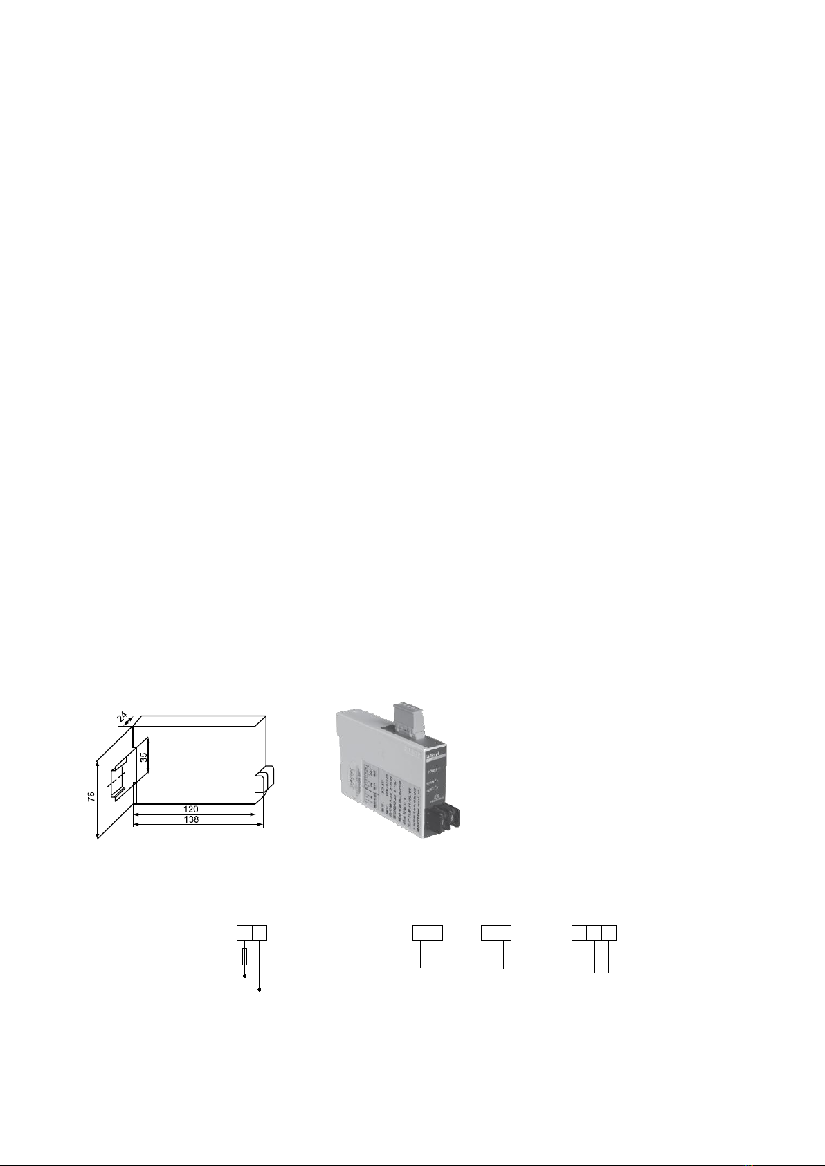
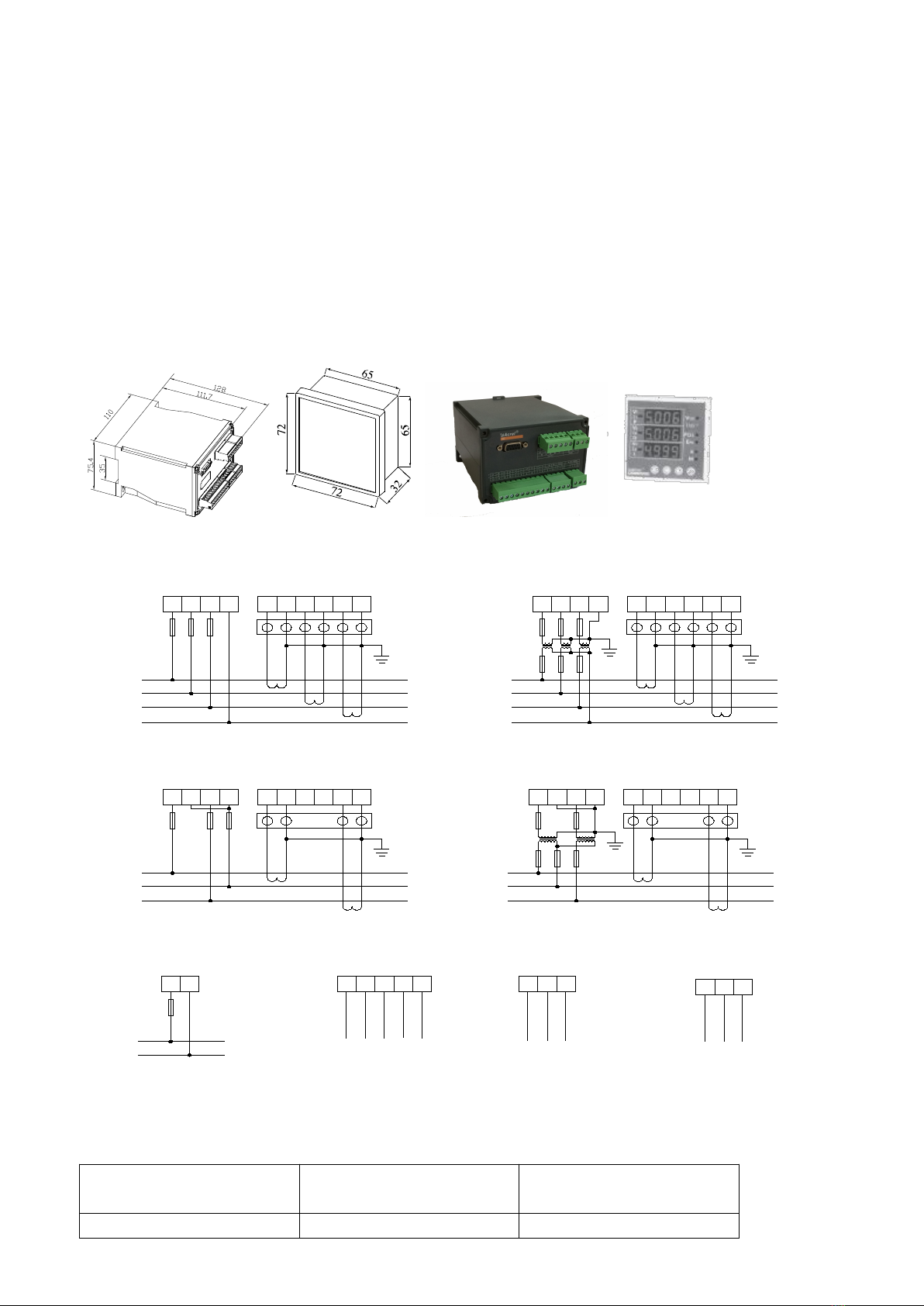
外形尺寸
Outline dimension
接线方式
Wiring
L N
FUSE
I、U
辅助电源:AC 85~265V DC 100~350V
L
N
-
5 63 41 2 2223
+
+
输入 输出
AB
RS485通讯
AC 85~265V DC 100~350V Auxiliary power supply Input Output RS485 Communication
订货范例
例 型 号:BD-AI

4
辅助电源:AC220V/50Hz
输 入:5A
输 出:4~20mA
Order example
E.g. Type: BD-AI
Auxiliary power supply: AC220V/50Hz
Input: 5A
Output: 4~20mA
注:仅仪表 BD-AI、BD-AV 可带 RS485 通讯功能。
4.2 三相电流、电压变送器
4.2 Three-phase current, voltage transmitters
用途
测量三相电流、电压信号,隔离变送输出三路模拟信号。
Usage
Measure three-phase current or voltage, isolate and transmit 3-channel analog output.
产品规格
BD-3I3 三相电流变送器
BD-3V3 三相三线电压变送器
BD-4V3 三相四线电压变送器
Specification
BD-3I3 Three-phase current transmitters
BD-3V3 Three-phase 3-wire voltage transmitters
BD-4V3 Three-phase 4-wire voltage transmitters
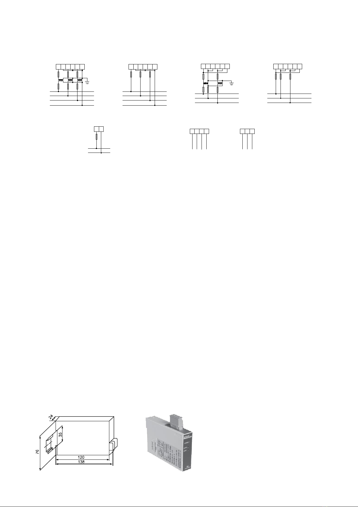
外形尺寸
Outline dimension
接线方式
Wiring
电流变送器
Current transmitters
A
B
C
电流输入
IA
*IAIB
*IBIC
*IC
S1 S2
S1 S2
S1 S2
* * *
*
*
*
3 4 5 6 7 8
L N
FUSE
辅助电源:AC 85~265V
DC 100~350V
L
N
1 2
AO3 AO2 AO1
模拟量输出
14 12 10 9
COM A B
RS485通讯
22 23
AC 85~265V DC 100~350V
Auxiliary power supply Current input
Analog output RS485 Communication
5
电压变送器
Voltage transmitters
A
B
C
电压(三相四线3PT)
N
A
B
C
电压(三相四线无PT)
N
UAUBUC
UNUNUNUAUBUC
UNUNUN
FUSES FUSES
A
B
C
电压(三相三线2PT)
A
B
C
电压(三相三线无PT)
UAUBUBUCUCUAUAUBUBUCUCUA
FUSES FUSES
3 4 5 6 7 8 3 4 5 6 7 8 3 4 5 6 7 8
3 4 5 6 7 8
AO3 AO2 AO1
模拟量输出
14 12 10 9
COM A B
RS485通讯
22 23
L N
FUSE
辅助电源:AC 85~265V DC 100~350V
L
N
1 2
AC 85~265V DC 100~350V Auxiliary power supply
Voltage(three-phase 4-wire 3PT) Voltage(three-phase 4-wire no-PT) Voltage(three-phase 3-wire 2PT) Voltage(three-phase 3-wire no-PT)
Analoge output RS485 Communication
订货范例
例 型 号:BD-3I3
辅助电源:AC220V/50Hz
输 入:5A
输 出:三相 4~20mA
Order example
E.g. Type: BD-3I3
Auxiliary power supply: AC220V/50Hz
Input: 5A
Output: 3-channel 4~20mA
4.3 热电阻变送器
4.3 RTDtransmitters
用途
RTD 输入,比例输出 2000V 隔离的 DC(4-20mA,0-20mA,0-5V 或0-10V)信号。模块内具有浪涌保护电
路,也适用于恶劣的环境工作。
Usage
The module have features of power supply by output circuit, RTD input, 4~20mA signal output to be isolated
from 2000V, fitted with surge protection circuit , so fits for foul environment.
产品规格
BD-TR/I, BD-TR/V
Specification
BD-TR/I, BD-TR/V
外形尺寸
Outline dimension

6
接线方式
Wiring
二线RTD输入
5 4 3
+
三线RTD输入
5 4 3
+
输出
76
+
-
4-20mA
2-wire RTD Input 3-wire RTD Input Output
L N
FUSE
辅助电源:AC 85~265V
DC 100~350V
L
N
1 2
AC 85~265V DC 100~350V
Auxiliary power supply
订货范例
例 型 号:BD-TR/I
辅助电源:AC220V/50Hz
输 入:PT100 0~200℃
输 出:4~20mA
Order example
E.g. Type: BD-TR/I
Auxiliary power supply: AC220V/50Hz
Input: PT100 0~200℃
Output: 4~20mA
4.4 智能温度变送器
4.4 Intelligent temperature transmitters
用途
输入信号为热电阻(PTl00),并带有温度显示功能,经隔离转换成标准的模拟量( 4-20mA 或0-20mA 或0-5V
或0-10V)输出,既可直接与指针表、数显表相接,也可以与自控仪表(如 PLC)、各种 A/D 转换器、以及计
算机系统配接。
Usage
RTDinput and temperature display function, isolate and transmit into standard anlaog output (4-20mA or
0-20mA or 0-5V or 0-10V). It can directly connect pointer digital display meters, and matches with automation
meters (PLC), kinds of A/D converter, computer system.
产品规格
BD-TRA 智能温度变送器
Specification
BD-TRA intelligent temperature transmitters
外形尺寸
Outline dimension

7
接线方式
Wiring
三线RTD输入
5 6
输出
+
74 3
-+
L N
FUSE
辅助电源:AC 85~265V
DC 100~350V
L
N
1 2
AC 85~265V DC 100~350V
Auxiliary power supply
3-wire RTD Input Output
订货范例
例 型 号:BD-TRA
辅助电源:AC220V/50Hz
输 入:PT100 0~200℃
输 出:4~20mA
Order example
E.g. Type: BD-TRA
Auxiliary power supply: AC220V/50Hz
Input: PT100 0~200℃
Output: 4~20mA
4.5 功率变送器
4.5 Power transmitters
用途
能测量有功功率,无功功率,隔离变送输出模拟信号。
Usage
Measure active power, reactive power, isolate and transmit analog output.
产品规格
BD-3P 三相三线有功功率变送器
BD-3Q 三相三线无功功率变送器
BD-3P/Q/I 三相三线有功功率/无功功率/电流组合变送器
BD-4P/Q/I 三相四线有功功率/无功功率/电流组合变送器
BD-4P 三相四线有功功率变送器
BD-4Q 三相四线无功功率变送器
Specification
BD-3P Three-phase 3-wire active power transmitters
BD-3Q Three-phase 3-wire reactive power transmitters
BD-3P/Q/I Three-phase 3-wire active power/reactive power/current combination transmitters
BD-4P/Q/I Three-phase 4-wire active power/reactive power/current combination transmitters
BD-4P Three-phase 4-wire active power transmitters
BD-4Q Three-phase 4-wire reactive power transmitters
外形尺寸
Outline dimension

8
接线方式
Wiring
订货范例
例 型 号:BD-3P
辅助电源:AC220V/50Hz
输 入:电流 5A 电压 100V 功率 866W
输 出:4~20mA 对应 0~866W
Order example
E.g. Type: BD-3P
Auxiliary power supply: AC220V/50Hz
Input: Current/5A Voltage/100V Power/866W
Output: 4~20mA corresponds 0~866W
A
B
C
N
UAUBUCUNIA
*IAIB
*IBIC
*IC
FUSES
A
B
C
N
UAUBUCUNIA
*IAIB
*IBIC
*IC
FUSES
A
B
C
UAUBUCUNIA
*IAIB
*IBIC
*IC
FUSES
A
B
C
UAUBUCUNIA
*IAIB
*IBIC
*IC
FUSES
三 相 四 线 3CT 三 相 四 线 3PT、 3CT
三 相 三 线 2CT 三 相 三 线 2PT、 2CT
L N
FUSE
辅 助 电 源
S1 S2
S1 S2
S1 S2
S1 S2
S1 S2
S1 S2
S1 S2
S1 S2
S1 S2
S1 S2
L
N
* * * * * *
* * ** * *
*
*
*
*
*
*
*
*
*
*
1 2
3 4 5 6 7 83 4 5 6 7 8
3 4 5 6 7 8 3 4 5 6 7 8
13 14 15 16 13 14 15 16
13 14 15 16 13 14 15 16
22 23
AB
RS485通 讯
17 18
A0 1
P/Q/I模 拟 量 输 出
19 20 21
A0 2 A03A04 COM
++ + +
Three-pha s e 4-wire 3CT Three-pha s e 4-wire 3PT,3CT
Three-pha s e 3-wire 2CT Three-pha s e 3-wire 2PT,2CT
P/Q/I Analog output RS485 Communication
Auxiliary power supply
9
4.6 功率因数变送器
4.6 Power factor transmitters
用途
用于测量单、三相系统的功率因数,经隔离变换成直流信号输出,供远动装置,计算机,自动化控制系
统作信息输入,广泛应用于电力系统场合。
Usage
Measure power factor of single, three-phase system, isolate and transmit into DC signal output. It is used for
information input of telemechanism, computer, automation control system. It is widely used in electric power system.
产品规格
BD-PF
Specification
BD-PF
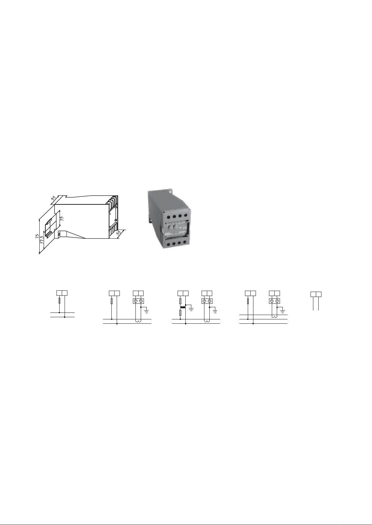
外形尺寸
Outline dimension
接线方式/Wiring
Wiring
L
N
UAUNIA
*IA
FUSE
单相1CT
L
N
UAUN
单相1PT、1CT
FUSE
IA
*IA
S1 S2
S1 S2
**
* *
3 45 6 3 45 6
输出
7 8
+ -
B
C
UBUCIA
*IA
FUSE
三相
S1 S2
*
*
3 45 6
A
L N
FUSE
辅助电源:AC 85~265V
DC 100~350V
L
N
1 2
AC 85~265V DC 100~350V
Auxiliary power supply Single phase 1CT Single phase 1PT, 1CT Three-phase
Output
订货范例
例 型 号:BD-PF
辅助电源:AC220V/50Hz
输 入:电流 5A 电压 100V
输 出:4~20mA 对应 0~1
Order example
E.g. Type: BD-PF
Auxiliary power supply: AC220V/50Hz
Input: Current/5A Voltage/100V
Output: 4~20mA corresponds 0~1
4.7 频率变送器
4.7 Frequency transmitters
用途
可测量工频频率,将频率变换为线性输出的直流信号,隔离输送给远动装置、计算机、巡检等。
10
Usage
Measure frequency, transmit frequency into linear DC signal output, then isolate and deliver to telemechanics
device, computer and so on.
产品规格
BD-F
Specification
BD-F
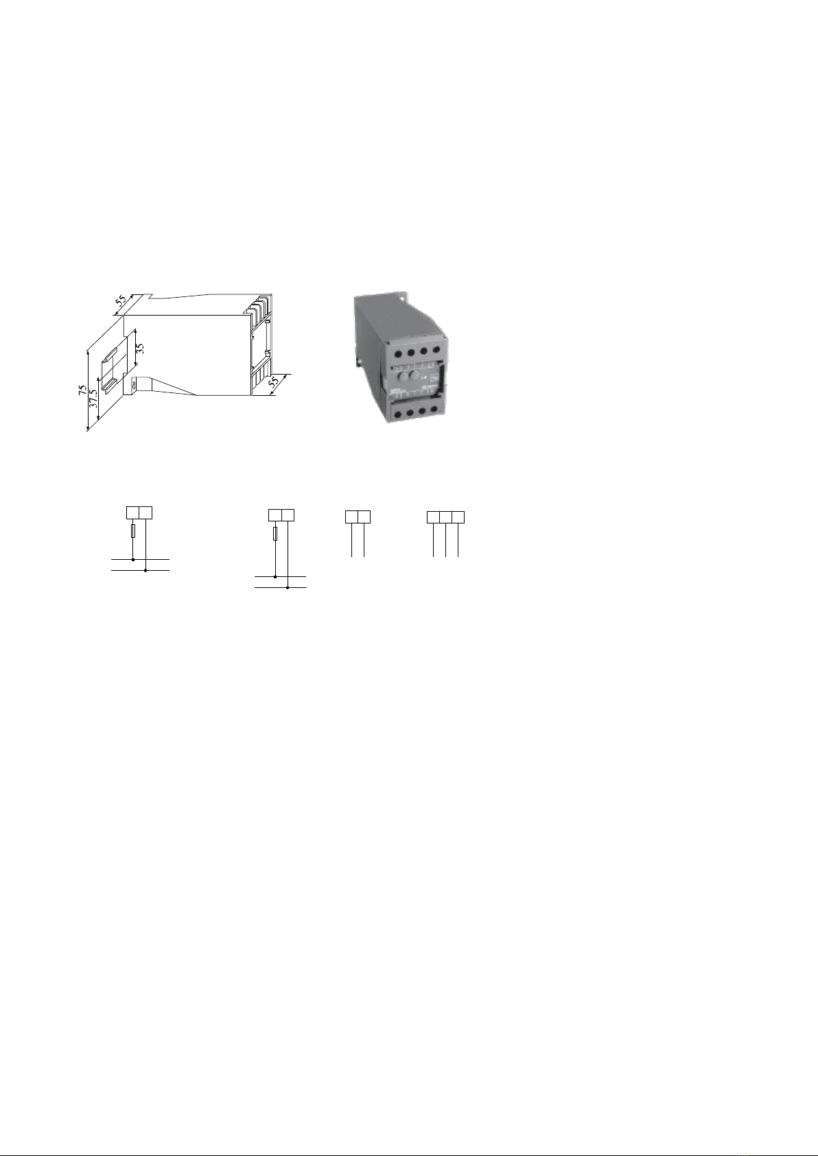
外形尺寸
Outline dimension
接线方式
Wiring
L
N
UAUN
FUSE
输入
3 4
输出
5 6
+-
RS485通讯
22 23
AB
L N
FUSE
辅助电源:AC 85~265V
DC 100~350V
L
N
1 2
AC 85~265V DC 100~350V
Auxiliary power supply Input
Output RS485 Communication
订货范例
例 型 号:BD-F
辅助电源:220V/50Hz
输 入:100V
输 出:4~20mA 对应 45~50~55Hz
Order example
E.g. Type: BD-F
Auxiliary power supply: 220V/50Hz
Input: 100V
Output: 4~20mA Corresponds 45~50~55Hz
4.8 多电量数字变送器
4.8 Multi-electrical parameters digital transmitters
用途
将电力系统中的电度量转换成高线性比例输出的脉冲量。该变送器带 RS485 通讯接口,采用 Modbus 协
议,可输出三相电流、电压、有功功率、无功功率、频率、功率因数、有功电度、无功电度等数字量,1~4
路模拟量可选,两路电能脉冲输出。
Usage
Transmit kWh value of electric power system into high linear pulse. It has RS485 communication interface,
adopts Modbus protocol, and exports three-phase current, voltage, active power, reactive power, frequency, power
factor, active energy reactive energy and so on. 1~4 channel analog optional, two channel electric energy pluse
11
output.
产品规格
BD-3E 三相三线多电量数字变送器
BD-4E 三相四线多电量数字变送器
BD-4EA 组合式多功能电力仪表,外接显示头
Specification
BD-3E Three-phase 3-wire Multi-electrical parameters digital transmitters
BD-4E Three-phase 4-wire Multi-electrical parameters digital transmitters
BD-4EA Combined multi-functional power meters
外形尺寸
Outline dimension
接线方式
Wiring
例:输入信号为 AC 100V 5A 时,4路变送输出对应关系
E.g. Input singal is AC 100V 5A, 4-channel transmitting output corresponding relation
变送输出
Transmitting output
测试对象(26 个)
Measuring object
对应关系
Corresponding relation
AO1
P
4-20mA 对应 0-866W
A
B
C
N
UAUBUCUNIA
*IAIB
*IBIC
*IC
FUSES
A
B
C
N
UAUBUCUNIA
*IAIB
*IBIC
*IC
FUSES
A
B
C
UAUBUCUNIA
*IAIB
*IBIC
*IC
FUSES
A
B
C
UAUBUCUNIA
*IAIB
*IBIC
*IC
FUSES
三 相 四 线 3 C T 三 相 四 线 3 P T 、 3 C T
三 相 三 线 2 C T 三 相 三 线 2 P T 、 2 C T
L N
FUSE
辅 助 电 源
S 1 S 2
S 1 S 2
S 1 S 2
S 1 S 2
S 1 S 2
S 1 S 2
S 1 S 2
S 1 S 2
S 1 S 2
S 1 S 2
L
N
* * * * * *
* * ** * *
*
*
*
*
*
*
*
*
*
*
1 2
3 4 5 6 7 83 4 5 6 7 8
3 4 5 6 7 8 3 4 5 6 7 8
1 3 1 4 1 5 1 6 1 3 1 4 1 5 1 6
1 3 1 4 1 5 1 6 1 3 1 4 1 5 1 6
2 2 2 3
AB
RS485通 讯
1 7 1 8
A 0 1
P / Q / I 模 拟 量 输 出
1 9 2 0 2 1
A 0 2 A 0 3 A 0 4 COM
++ + +
Three-phase 4-wire 3CT Three-phase 4-wire 3PT,3CT
Three-phase 3-wire 2CT Three-phase 3-wire 2PT,2CT
P/Q/I Analog output RS485 Communication
Auxiliary power supply
91 0
Ep+ E -
电 能 脉 冲
1 1
E q +
Electric energy pulse

12
AO2
Q
4-20mA 对应 0-866var
AO3
Ia
4-20mA 对应 0-5A
AO4
PF
4-20mA 对应 0-1
订货范例
例 型 号:BD-3E
辅助电源:220V/50Hz
输 入:电流 5A 电压 100V 功率 866W
输 出:40000 脉冲/kWh
Order example
E.g. Type: BD-3E
Auxiliary power supply: 220V/50Hz
Input: Current/5A Voltage/100V Power/866W
Output: 40000 pulse/kWh
注:BD-4EA 组台式多功能电力仪表主要适合于 GCK、GCS、MNS 等低压抽屉柜的出线回路中,特别是电器
元件排列较为紧凑的场合。产品由信号采集处理部分(即 BD-4E)和显示器组成,BD-4E 安装在内部导轨上,
显示器安装在柜体面板上。功能与 ACR220E 一致。
Note: DT 80-E single-phase active electric energy meters are mainly suitable in the outlet circuits of low voltage
draw-out cubicles such as GCK, GCS, MNS etc., particularly used for position with electrical components layout in
more compact condition. It consists of BD-4E for acquiring and treating signal, displays. BD-4E is mounted onto the
inner guide rail, the display is mounted onto the face place of cubide. Its function is identical with that of ACR 220E
5 操作指南 Operating guide
依照说明正确接线后,接通工作电源即进入测量状态。
After as per description and correct connection, switching-on working power supply, then enter the measuring
condition.
5 1 查看状态(查看电流、电压、功率和电度和频率)
在测量状态下,单击相应功能键可以依次切换查看:电压 V、电流 I、有功功率、无功功率、功率因数、
有功电度 Ep 和无功电度 Eq 及频率。
■电压显示一次侧值,单位为 V,当一次测电压达到预定界限时,显示单位转换为 kV。
■电流显示一次侧值,单位为 A,当一次测电流达到预定界限时,显示单位转换为 kA。
■功率显示一次侧值,有功功率单位为 W,无功功率单位为 Var,当功率值达到预定界限时,显示单位
转换为 kW 或者 MW 和kVar 或者 MVar,当接线方式为三相四线时,如果出现某相有功功率或功率因数为负
值,则有可能该相电流进线与出线接反。
■显示电度为一次侧值,电度显示的单位固定为 kWh,当显示电度时,显示两位小数,即精确到 0.01 kWh。
5.1 View Status (View current, voltage, power and electric energy and frequency)
Under measuring conditionm click corresponding function key, switching View orderly: voltage V, frequency,
current I, power PQS, power factor, switching input/output status, active electric energy Eq and reactive electric
energy Eq and time.
■voltage display primary side value, unit: V, when primary side voltage reached preset bound, display unit
convert as kV.
■current display primary side value, unit: A, when primary side current reached preset bound, display unit
convert as kA.
■power display primary side value, active power unit: W, reactive power unit: Var, when power value reached
preset bound, display unit convert as kW or MW and kVar or MVar, when connection mode as four wire three phase,
if active power or power factor of one phase is negative value, it is possible that connection of current inlet and outlet
of this phase is just reversal.
■display electric energy as secondary side value, electric energy display unit only as kWh, when display

13
electric energy, it should be expressed with two decimal points, i.e. with accuracy to 0.01 kWh.
5.2 操作字符说明
5.2 Operation character Description
字符
Character
文字说明
Textual description
字符
Character
文字说明
Textual description
PASS
密码
Password
InCt
电流网络
Current network
Addr
地址
Address
In-I
输入电压范围
Input current range
bAUd
波特率
Baud rate
Ct
电流倍率
Current magnification
UnEt
电压网络
Voltage network
Tr-x(x=1,2,3,4)
变送输出设置
Transmitting output setting
L3.3
三相三线
Three phase three wire
SYS
系统设置
System setting
L3.4
三相四线
Four wire three phase
CodE
设置密码
Setting password
In-U
输入电压范围
Input voltage range
CLr.E
电能清零
Electric energy zero clearing
Pt
电压倍率
Voltage magnification
5.3 系统设置模式
5.3 System setting mode
5.3.1 进入/退出系统设置模式
在正常情况下,仪表处于正常工作状态,按下 SET 键,再按回车键会进入系统设置模式,进入系统设置
模式前,首先需要输入正确的密码 PASS(出厂时设置为 0001)。
输入密码的方法为:
(1)按SET 键,再按回车键进入输入密码状态;
(2)按左右方向键减小或增大数值大小至正确的密码(可以同时按左或右方向键+回车键即可实现对百或十
位数字的减小或增大);
(3)按回车键确认数据进入系统设置模式。
■如果密码输入正确,即进入系统设置模式。
■仪表出厂时密码设置为 0001。
■在系统设置模式下,任何时候连续单击 SET 键都能退出系统设置模式并询问是否保存设置(按回车键
保存,按 SET 键不保存,按其他键继续设置)后返回到测量状态。
■系统设置模式下的各项目都被存储在存储器中,一旦设置成功,再次设置前,一直有效。
5.3.1 Enter/Exit system setting mode
Under normal condition, meter is in normal working condition, press down SET and ENTER, will enter system
setting mode, before enter system setting mode, firstly, enter correct password PASS (generally, the deliver setting is
0001).
Method of enter password:
(1) press SET, then press ENTER again to enter pressing password condition;
(2) press left/right direction key, decrease/increase number up to correct password (Press down left/right
direction key+ ENTER key at the same time can implement decrease/increase the hundreds'digit/tens'digit number);
(3) Press ENTER, to confirm data entered system setting mode.
■If pressing correct password, then entering system setting mode.

14
■Meter's deliver default password setting is 0001.
■Under system setting mode, at any time, click SET continuously, can exit system setting mode and inquire:
save setting? (press ENTER to save, and press SET for Don't Save, press other key to continue setting) then return to
measuring condition.
■Under system setting mode, each item is stored in storage, after successful setting, before next setting, it is
always valid.
5.3.2 系统设置模式下的操作
系统设置模式下,SET 键用来返回上级菜单,左右键用来切换设置的项目或者改变需要设置的内容,回
车键用来确认需要设置的项目。系统设置模式下主要有以下设置项目:通讯地址及波特率设置(Addr,bAUd),
输入信号状况设置,变送输出设置(tr-l~tr-4),密码(CodE)及清零(CLr.E)设置(SYS 下)。
5.3.2 0peration under system setting mode
Under system setting mode, SET key is used for return to previous menu, left key and right key is used for
switching setting item or changing the content to be setting, ENTER is used for confirm the item to be setting.
System setting mode have following primary setting items: Communication Address setting and Baud rate setting
(Addr, bAUd), input signal condition setting, transmitting output setting (tr-l~tr-4), password (CodE) and zero
clearing (CLr.E) setting (SYS).
5 3 3 变送输出设置
模拟变送输出可将电网中常见的 26 个电量(UA、UB、UC、UAB、UBC、UCA、IA、IB、IC、PA、PB、
PC、P总、QA、OB、QC、Q总、PFA、PFB、PFC、PF、SA、SB、SC、S总、F)中的其中最多四个量隔离
变送输出为 4~20mA 的直流信号。
5.3.3 Transmitting output setting
For common grid 26 electric parameters(UA 、UB、UC、UAB、UBC、UCA、IA、IB、IC、PA、PB、PC、
P total、QA、QB、QC、Q total、PFA、PFB、PFC、PF、SA、SB、SC、S total、F ), the analog transmitting output
can mostly isolate 4 items to transmit output DC signal of 4~20mA.
显示
Display
意义
Meaning
9
10 11 12
设置序号
Setting serial number
tr-1
tr-2 tr-3 tr-4
变送设置符号及序数
Transmit setting symbol and ordinal number
102
102 102 102
左起第一位为变送选择,如果是 4-20mA 输出,则为 1;第三、四
位为变送量的选择,01 代表 UA,02 代表 UB......26 代表频率(即
将上面提到的 26 个电量按顺序 1~26 进行排序)
The first left bit is transmitting selection, 4-20mA output=1; the third,
the fourth bit is transmitting quantity selection, 01 represent UA, 02
represent UB......26 represent frequency (Sort above 26 electric
parameters as sequence l~26)
5000
5000 5000 5000
20mA 对应显示值,取最高四位整数(小数点忽略)不足后面补 0。
例如电流 600A/5A,则当 600A 对应 20mA 时,该值设为 6000;
若要设置功率时,如 10kV/100V, 600A/5A,三相四线,则 100%
功率为 10kV×600A×
3
=1039.2kW,则该值为 1039;若三相三
线则为 10kV×600A×
3
=1039.2kW,该值设为 1039
20mA corresponding to displayed value, take highest four-digit

15
integers (ignoring decimal point) with 0 occupy lacking bit. Example:
current 600A/5A, when 600A corresponding to 20mA, setting=6000;
For setting power, as 10k/100V, 600A/5A, four wire three phase, then
100% power is l0kV×600A×
3
=1039.2kW, Value=1039; For
three phase three wire then l0kV×600A×
3
=1039.2kW,
Value=1039
6 通讯指南 Communication guide
6.1 通讯
在本章主要讲述如何利用软件通过通讯口来操控该变送器。本章内容的掌握需要您具有 MODBUS 协议
的知识储备并且通读了本册其它章节所有内容,对本产品功能和应用概念有较全面了解。
本章内容包括:MODBUS 协议简述,通讯应用格式详解,本机的应用细节及参量地址表。
6.1 Communication
This chapter mainly describes how to use software through communication port to operate and control this
transmitter. To grasp content in this chapter, you should have enough knowledge accumulation of MODBUS protocol,
read and familiar with all content of this manual, and full understanding of functions and application concept of this
product.
This section covers: MODBUS protocol compendium, expounding communication apply formatting, details for
applying this machine and parameter address table.
6.2 MODBUS 协议简述
BD-3E(A)/BD-4E(A)多电量组合变送器使用的是 MODBUS-RTU 通讯协议,MODBUS 协议详细定义了校
验码、数据序列等,这些都是特定数据交换的必要内容。MODBUS 协议在一根通讯线上使用主从应答式连接
(半双工),这意味着在一根单独的通讯线上信号沿着相反的两个方向传输。首先,主计算机的信号寻址到一
台唯一的终端设备(从机),然后,终端设备发出的应答信号以相反的方向传输给主机。
MODBUS 协议只允许在主机(PC,PLC 等)和终端设备之间通讯,而不允许独立的终端设备之间的数
据交换,这样各终端设备不会在它们初始化时占据通讯线路,而仅限于响应到达本机的查询信号。
6.2 MODBUS protocol compendium
BD-3E(A)/BD-4E(A) multiple electric parameters combined transmitter use MODBUS-RTU communication
protocol, MODBUS protocol define detailedly: check code, data sequence etc., these are necessary content for
specific data exchange. MODBUS protocol use master/slave responding connection (half-duplex) on one
communication line, this means on one separated communication line, signal transmit in opposite directions. Firstly,
master computer signal addressed only one terminal device (slave), then, the reply signal sent by terminal device
transmit to the master in opposite directions.
MODBUS protocol only allow communication between the master (PC, PLCetc.) and terminal device, but not
allow data exchange between independent terminal devices, so, each terminal device does not occupy communication
line in the initialization, only respond query signal reach to the computer.
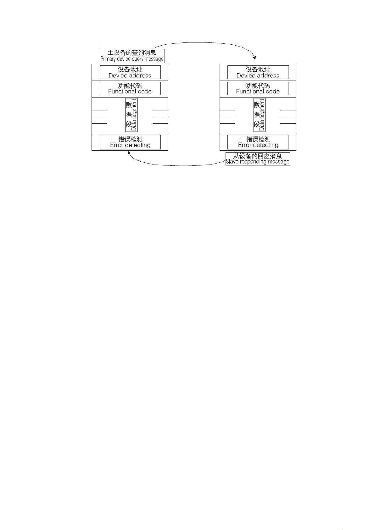
6.3 查询—回应周期
6.3 Query-respond period
16
主一从 查询—回应周期表
Master - slave query-respond period table
6.3.1 查询
查询消息中的功能代码告之被选中的从设备要执行何种功能。数据段包含了从设备要执行功能的任何附
加信息。例如功能代码 03 是要求从设备读保持寄存器并返回它们的内容。数据段必须包含要告之从设备的信
息:从何寄存器开始读及要读的寄存器数量。错误检测域为从设备提供了一种验证消息内容是否正确的方法。
6.3.1 Query
The functional code of query message tells the selected slave device to implement what function. Data segment
included any additional message implemented function by slave device. For example: functional code03 demand
slave device to read holding register and return their content. The data segment must include message to be telling to
slave device: the register starting read and register quantity to be read. Error detecting domain provide slave device
with one method to verify the message content is correct or not.
6.3.2 回应
如果从设备产生一正常的回应,在回应消息中的功能代码是在查询消息中的功能代码的回应。数据段包
括了从设备收集的数据:如寄存器值或状态。如果有错误发生,功能代码将被修改以用于指出回应消息是错
误的,同时数据段包含了描述此错误信息的代码。错误检测域允许主设备确认消息内容是否可用。
6.3.2 Respond
If slave device produce one normal respond, the functional code of respond message is enquiring the respond of
functional code of query message. The data segment include data collected by slave device: such as register value or
condition. If error occur, functional code will be revised to indicate that the respond message is wrong, while the data
segment include code describing this error message. Error detecting domain allow primary device to confirm message
content is usable or not.
6.4 传输方式
传输方式是指一个数据帧内一系列独立的数据结构以及用于传输数据的有限规则,下面定义了与
MODBUS 协议- RTU 方式相兼容的传输方式。
每个字节的位
■1个起始位
■18 个数据位,最小的有效位先发送
■无奇偶校验位
■1个停止位

17
错误检测(Error checking)
CRC(循环冗余校验)
6.4 Transmission mode
Transmission mode refer to one series of independent data structure, and limited regulation used for transmission
data in one data frame, the transmission mode compatible with MODBUS protocol-RTU mode is defined as follows:
Bit of each byte:
■One start bit
■Eight data bit, least significance bit first transmitting
■Non-Parity bit
■1 stop bit
Error detecting (Error checking)
CRC (cyclic redundancy check)
6.5 协议
当数据帧到达终端设备时,它通过一个简单的“端口”进入被寻址到的设备,该设备去掉数据帧的“信
封”(数据头),读取数据,如果没有错误,就执行数据所请求的任务,然后,它将自己生成的数据加入到取
得的“信封”中,把数据帧返回给发送者。返回的响应数据中包含了以下内容:终端从机地址(Address)、被
执行了的命令(Function)、执行命令生成的被请求数据(Data)和一个校验码(Check)。发生任何错误都不会有成
功的响应,或者返回一个错误指示帧。
6.5 Protocol
When Data frame reach terminal device, enter addressed device by a simple "port" this device remove Data frame
"envelope" (data head), read data, if there is no error, executing task requested by data, then, add the new produced
data in the obtained "envelope", return the data frame to the transmitter. Returned responding data include following
content: slave terminal address (Address), executed command (Function), requested data produced by executing
command (Data) and one CRC check code (Check). If any error occur, no successful responding or returning one
error indication frame.
6.5.1 数据帧格式
6.5.1 Protocol
地址 Address
功能 Function
数据 Data
校验 Check
8-Bits
8-Bits
N×8-Bits
16-Bits
6.5.2 地址域
地址域在帧的开始部分,由一个字节(8位二进制码)组成,十进制为 0~255,在我们的系统中只使用
1~247,其它地址保留。这些位标明了用户指定的终端设备的地址,该设备将接收来自与之相连的主机数据。
每个终端设备的地址必须是唯一的,仅仅被寻址到的终端会响应包含了该地址的查询。当终端发送回一个响
应,响应中的从机地址数据便告诉了主机哪台终端正与之进行通信。
6.5.2 Address domain
Address domain is located at beginning of frame, composed of one byte (8 bit binary system domain), decimal
system is 0~255, in the ACR meters, just l~247 is used, other address is Reserved. these bits indicate terminal device
address specified by users, this device will receive the connecting host computer data. Every terminal device has its
only one address, only the addressing terminal is responding enquiry including this address. When terminal is
Transmitting one responding, the responding slave address data tell host computer that which terminal is
communicating with it.
6.5.3 功能域
功能域代码告诉了被寻址到的终端执行何种功能。下表列出了该变送器用到的功能码,以及它们的意义
Table of contents


