Acrimo 7700 User manual

Installation Instructions - PERGOLINE
Contents:
1. Safety
1.1. Explanation of the safety notes
1.2. General safety information
2. Installation
2.1. Tools, resources and materials
2.2. Preparing the installation
2.3. Wind classes: Definition and classification
2.4. Mounting situations: Wall and ceiling installation
2.5. Mounting height and position of the brackets
2.6. Fastening technique
2.7. Mounting the casing:
2.8. Mounting rails and posts
2.9. Mounting the distance tube(s)
2.10. Alignment of the system
3. Line systems
4. Initial operation
4.1. Completing the installation / Transfer to the client
5. Dismounting
6. Troubleshooting
1. Safety notes, warnings and mounting information:
1.1. Explanation of the safety notes:
Safety notes and important information are integrated in the text as appropriate.
The following symbols are used to alert the reader/user of the instructions.
This symbol means that the relevant note is important for the safety of persons or
for the function of the awning.
This symbol highlights important product information for the installation engineer
or user.
1.2. General safety information:
The WO&WO PERGOLINE awning has been designed and manufactured in
conformity with DIN EN 13561. However, when the awning is mounted or operated,
the persons involved in the respective activity may be put at risk if the relevant
instructions are not observed.
Only qualified and duly specialised companies or trained specialist personnel may be
permitted to mount the awning.
Always observe the information and notes in the installation and operation
instructions.

A failure to observe the relevant information will render the manufacturer’s liability
null and void.
The safety-at-work and accident prevention regulations specific to each country must
be complied with. In particular, a person performing special work at height must be
suitably secured.
The notes on the product and its packaging must be observed.
2. Installation:
2.1. Tools, resources and materials:
•Measuring tape 10m
•(Percussion) drilling machine
•Cordless screwdriver
•Drill bits, suitable for the drilling substrate and the mounting pieces
•SW 4, SW 5; SW 6 and SW 8 Allen keys
•Torx bit Tx 25
•Ratchet (catrake) with extension and sockets, respectively ring spanners SW 13 and
SW 17
•Steel drill bits, diameter 4.5mm and 5.5mm
•Spirit level and string for alignment of the brackets
•Test cable, resp. adjustment set (for initial operation)
•Aluminium chop saw to shorten the posts
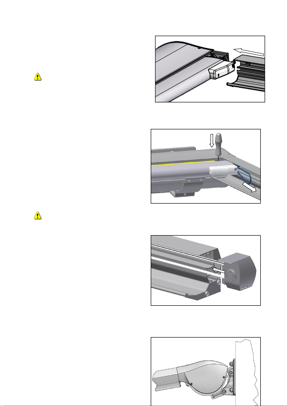
2.2. Preparing the installation:
Transport the awning to the site of installation, ensuring that the orientation is
correct. The location of the drive side is indicated on the packaging.
Secure the installation zone (the secured zone must be at least equivalent to the size
of the fully deployed awning).
If the awning is hoisted to higher installation positions with ropes, the awning must
be removed from the packaging.
When attaching the hoisting ropes, ensure that the awning is properly fastened, but
not damaged. Hoist the awning exclusively in horizontal position and evenly.
If the information above is not observed, the awning system may fall down and put
the health of persons at risk!
2.3. Wind resistance classes:
Definition:
DIN EN 13561 Item 4.3. defines different wind resistance classes for awnings. The
classification depends on the quality of the product. The higher the class, the better the
quality of the product.
Wind resistance
class
Description
Wind force
Wind speed
Class 0
undefined, product not tested or unsuitable
Class 1
light
breeze
4 (according to
Beaufort wind scale)
20 - 27 km/h

Class 2
fresh
breeze
5 (according to
Beaufort wind scale)
28 -37 km/h
Class 3
strong
breeze
6 (according to
Beaufort wind scale)
38 -48 km/h
Classification of the PERGOLINE:Wind resistance class 2
2.4. Mounting situations:
Wall installation of PERGOLINE
DURCHGANGSHÖHE = HEADROOM
approx. 35mm
Ceiling installation of PERGOLINE with angle towards the back or towards the front

DURCHGANGSHÖHE = HEADROOM
approx. 75mm
approx. 175mm
2.5. Mounting height and position of the brackets
Mounting height: The awning can produce crushing forces and shear stresses, for
instance between the fall bar and the distance tube or casing and at the rollers of the
moving fall bar. To protect human safety, the mounting height must be at least
2,50m. If the situation requires a mounting height less than the stated minimum
height, the awning must be operated exclusively with a switch mounted at a location
from where the moving parts can be observed.
Position of the brackets:
Do not exceed the maximum
fixing positions of the
brackets! This could lead to
damages to, respectively
malfunctions of, the awning.
ACHSMASS = DISTANCE BETWEEN AXES
ANLAGENBREITE = SYSTEM WIDTH
Drilling holes for the brackets:
Transfer the drilling outlines of the brackets
to the determined bracket positions.
Select the appropriate drill bit for the
respective base material and mounting
method.
2.6. Mounting technique:
Due to the own weight of the awning and the maximum wind load, the dowels can be
subjected to pulling forces up to 650N (approximately 65kg).
If the supporting capacity of the base material is less than that of concrete and if
injection anchors are used, please consult a qualified mounting engineer.

Mounting on thermally insulated facades:
Insulating plaster and full multi-layer
thermal insulation are not pressure stable.
Therefore, it is necessary to use backing
for the entire surface, or at least
distancers for the area around the screws.
The picture on the right illustrates one
possible variant:
Bracket mounting:
Loosely fasten all brackets and achieve
true alignment.
Even out irregularities of the base by
using suitable spacers.
Then tighten all screws and check that
brackets are firmly attached.
2.7. Mounting the casing:
Ensure that sufficient personnel is
available to lift the awning. The awning
weighs up to 85kg; the weights are
defined on the packaging.
At first ensure that both brackets have the
same inclination. Then hook up the
awning (slightly tilted upwards) in the rear
locking element of the bracket and lower it
down.
Secure the casing with round head
screws and the square nuts inserted in
the front clamping channel of the casing.
If the installation is made with ceiling
angles, the brackets must be tilted to
hook up the box.
Pre-adjusting the inclination:
•Loosen the two side screws of the
brackets with SW 8 Allen key.
•Adjust the inclination by
turning the screw in the
Distance tube
Dämmschutz
ausgenommen
Insulation protection
taken out
Table of contents
Popular Lawn And Garden Equipment manuals by other brands

Sunforce
Sunforce SOLAR user manual

GARDEN OF EDEN
GARDEN OF EDEN 55627 user manual

Goizper Group
Goizper Group MATABI POLMINOR instruction manual

Rain Bird
Rain Bird 11000 Series Operation & maintenance manual

Cub Cadet
Cub Cadet BB 230 brochure

EXTOL PREMIUM
EXTOL PREMIUM 8891590 Translation of the original user manual

Vertex
Vertex 1/3 HP Maintenance instructions

GHE
GHE AeroFlo 80 manual

Land Pride
Land Pride Post Hole Diggers HD25 Operator's manual

Yazoo/Kees
Yazoo/Kees Z9 Commercial Collection System Z9A Operator's & parts manual

Premier designs
Premier designs WindGarden 26829 Assembly instructions

Snapper
Snapper 1691351 installation instructions