Acromag XVME-6300 User manual

Acromag, Inc. Tel: 248-295-0310
- i -
www.acromag.com
XVME-6300
6U VME Intel i7 Core Processor Board
USER’S MANUAL
ACROMAG INCORPORATED
30765 South Wixom Road
Wixom, MI 48393-2417 U.S.A.
Tel: (248) 295-0310
Fax: (248) 624-9234
Copyright 2012, Acromag, Inc., Printed in the USA.
Data and specifications are subject to change without notice
8500981G

XVME-6300 6U VME Intel i7 Core Processor Board
Acromag, Inc. Tel: 248-295-0310
- ii -
www.acromag.com
Trademark Information
Brand or product names are trademarks or registered trademarks of their respective owners.
Intel® and Core-i7® are registered trademarks of Intel Corporation.
Windows® and Windows 7® are registered trademarks of Microsoft Corporation in the US and in other countries.
Copyright Information
This document is copyrighted by Xembedded, LLC (Xembedded) and shall not be reproduced or copied without
expressed written authorization from Xembedded.
The information contained within this document is subject to change without notice. Xembedded does not
guarantee the accuracy of the information.
WARNING
This is a Class A product. In a domestic environment this product may cause radio interference, in which case the
user may be required to take adequate measures.
Warning for European Users –Electromagnetic Compatibility
European Union Directive 89/336/EEC requires that this apparatus comply with relevant ITE EMC standards. EMC
compliance demands that this apparatus is installed within a VME enclosure designed to contain electromagnetic
radiation and which will provide protection for the apparatus with regard to electromagnetic immunity. This
enclosure must be fully shielded. An example of such an enclosure is a Schroff® 7U EMC-RFI VME System chassis,
which includes a front cover to complete the enclosure.
The connection of non-shielded equipment interface cables to this equipment will invalidate European Free Trade
Area (EFTA) EMC compliance and may result in electromagnetic interference and/or susceptibility levels that are in
violation of regulations which apply to the legal operation of this device. It is the responsibility of the system
integrator and/or user to apply the following directions, as well as those in the user manual, which relate to
installation and configuration:
All interface cables should be shielded, both inside and outside of the VME enclosure. Braid/foil type shields are
recommended for serial, parallel and SCSI interface cables. Where as external mouse cables are not generally
shielded, an internal mouse interface cable must either be shielded or looped (1 turn) through a ferrite bead at the
enclosure point of exit (bulkhead connector). External cable connectors must be metal with metal back-shells and
provide 360-degree protection about the interface wires. The cable shield must be terminated directly to the metal
connector shell; shield ground drain wires alone are not adequate. VME panel mount connectors that provide
interface to external cables (e.g., RS232, USB, keyboard, mouse, etc.) must have metal housings and provide direct
connection to the metal VME chassis. Connector ground drain wires are not adequate.
Environmental Protection Statement
This product has been manufactured to satisfy environmental protection requirements where possible. Many of the
components used (structural parts, printed circuit boards, connectors, batteries, etc.) are capable of being recycled.
Final disposition of this product after its service life must be accomplished in accordance with applicable country,
state, or local laws or regulations.

XVME-6300 6U VME Intel i7 Core Processor Board
Acromag, Inc. Tel: 248-295-0310
- iii -
www.acromag.com
Technical Support
In the unlikely event that you experience problems with your product, contact Technical Support. Please be
prepared to provide contact information and details of your problem. You may be asked for further details when
calling:
TELEPHONE: 248-626-1541E-mail: solutions@acromag..com

XVME-6300 6U VME Intel i7 Core Processor Board
Acromag, Inc. Tel: 248-295-0310
- iv -
www.acromag.com
Table of Contents
Introduction ......................................................................................................................................................................1
Module Features ............................................................................................................................................. 1
Architecture .................................................................................................................................................... 2
CPU Chip...................................................................................................................................................... 2
PCI –X Bus Interface ..................................................................................................................................... 2
Onboard Memory......................................................................................................................................... 2
Ethernet Controller....................................................................................................................................... 2
Storage Devices............................................................................................................................................ 3
VMEbus Interface......................................................................................................................................... 3
Serial Ports .................................................................................................................................................. 3
PMC Expansion ............................................................................................................................................ 3
Software Support ............................................................................................................................................ 4
XVME-6300 Xembedded Bios Settings .............................................................................................................. 4
Operational Block Diagram.............................................................................................................................. 7
Environmental Specifications ........................................................................................................................... 7
Hardware Specifications .................................................................................................................................. 8
VMEbus Specification .....................................................................................................................................10
Ordering Information .....................................................................................................................................10
Installation and Setup.....................................................................................................................................................11
Board Layout..................................................................................................................................................11
Jumper and Switch Settings ............................................................................................................................12
Connectors .....................................................................................................................................................15
FPANEL .......................................................................................................................................................15
SERIAL (on optional XBRD-9050 module)......................................................................................................16
VME P1.......................................................................................................................................................17
VME P2.......................................................................................................................................................18
VME P0.......................................................................................................................................................19
Registers ........................................................................................................................................................20
Register 0x20A80000h –User LED, Byte Swap, GPIN [3:0] Register ...............................................................20
Register 0x208000h –GPOUT [3:0] Register .................................................................................................21

XVME-6300 6U VME Intel i7 Core Processor Board
Acromag, Inc. Tel: 248-295-0310
- v -
www.acromag.com
Front Panel Layout .........................................................................................................................................22
Front Panel LEDs and Reset Switch...............................................................................................................22
Installing the XVME-6300 into a Backplane .....................................................................................................22
Programming..................................................................................................................................................................24
CPU Turbo Mode ............................................................................................................................................24
VME Interface ................................................................................................................................................24
System Resources........................................................................................................................................25
VMEbus Master Interface............................................................................................................................25
VMEbus Slave Interface...............................................................................................................................25
VMEbus Interrupt Handling .........................................................................................................................27
VMEbus Interrupt Generation......................................................................................................................27
VMEbus Reset Options ................................................................................................................................27
Software-Selectable Byte-Swapping Hardware................................................................................................27
Byte-Ordering Schemes ...............................................................................................................................28
Numeric Consistency ...................................................................................................................................29
Address Consistency ....................................................................................................................................30
Accessory Modules .........................................................................................................................................................32
XBRD-9050 .....................................................................................................................................................32
Jumpers ......................................................................................................................................................32
Ordering Information ..................................................................................................................................32
XVME-9630 ....................................................................................................................................................33
Jumpers ......................................................................................................................................................34
Connectors..................................................................................................................................................34
Accessory cables.............................................................................................................................................37
Revision History ..............................................................................................................................................................39

XVME-6300 6U VME Intel i7 Core Processor Board
Acromag, Inc. Tel: 248-295-0310
- 1 -
www.acromag.com
Introduction
Module Features
The XVME-6300 offers the following features:
Intel® Core™ i7 Processor. Available models are all dual-core: i7-610E at 2.53GHz, i7-620LE at 2GHz and i7-
620UE at 1.06GHz.
4GB or 8GB of DDR3 SDRAM running at 1033MHz (610E, 620LE) or 800MHz (620UE).
Two channels of SATA-300 out the P2. Use the XVME-9630 to provide the connectors needed to connect
external SATA drives.
Quad 10/100/1000 Base T Ethernet controllers with
oOne port out the front panel RJ-45 connector
oTwo ports out the P0 to support rear Ethernet (supports Vita 31.1)
oOne port available on the optional XBRD-9050 module
On-Board 1.8” Hard Drive using our XBRD-9050 module. This mounts in the PMC 2 site and does not allow for a
PMC module to be used.
VME64X VMEbus interface with programmable hardware byte swapping.
Support for Vita 31.1 Switch Fabric in compliant back planes.
Four serial ports:
oTwo switchable RS-232/RS-422/RS-485 serial ports (Com 1 & 2) on P2
oOne RS-232 serial port (Com3) on optional XBRD-9050 module
oOne RS-232 serial port on front panel (Com 4)
Six Universal Serial Bus (USB 2.0) ports:
oTwo on front panel connector
oTwo out P2
oTwo on optional XBRD-9050 module
PMC (PCI Mezzanine Card) sites with front panel I/O 32/64-bit 33/66/133MHZ PCI-X with full rear I/O using
optional P0 connector (PMC 1) and partial I/O using P2 connector (PMC 2).
Front panel ABORT/RESET switch with indicating lights. Red for “fail” and green for “pass”.
Ejector type handles in IEEE 1101.10 (CompactPCI type) or IEEE 1101.1 (legacy VME type).
Conduction cooled models available supporting -40C to 85C operational temperature range.

XVME-6300 6U VME Intel i7 Core Processor Board
Acromag, Inc. Tel: 248-295-0310
- 2 -
www.acromag.com
Architecture
CPU Chip
The Intel® i7 processors have a new micro-architecture, but remain software compatible with previous members
of the Intel® microprocessor family. The Intel® Core™ i7-610E, 620LE and 620UE all contain two cores that can
run independent processes, potentially doubling performance. With a maximum junction temperature of 105°C,
the Intel® Core™ i7 processors are capable of withstanding a great deal of thermal stress. The 18 watt Intel®
Core™ i7-620UE 1.06 GHz dual-core processors provide low power options and the 35W Intel® Core™ i7-610E
2.53GHz dual-core processors provide higher performance options.
PCI –X Bus Interface
The PLX8114 PCI Express x4 to PCI-X bridge provides a PCI-X bus for the TSI-148 and PMC interfaces capable of
32-bit/33MHz up to 64-bit/133MHz bus speeds.
PCI-X, or PCI extended, is an enhanced version of PCI (Peripheral Component Interconnect) computer bus.
Although PCI-X is backward-compatible with traditional 3.3V PCI 2.0 devices and systems, this specification
implements additional features and performance improvements include 3.3V signaling, increased speed grades
and adaptation to other form factors. PCI-X effectively doubles the speed and amount of data exchanged
between the computer processor and peripherals. PCI-X bus was designed for, and is ideally suited for, server
cards such as Fibre Channel, RAID, high-speed networking and other demanding devices.
Note that since the PMC connections share the PCI-X bus with the TSI-148 that the VME throughput may
suffer when PMC cards are plugged into the XVME-6300, especially if using a slower 33/66MHz PMC card. The
PCI-X bus can run up to 133MHz, but will slow down to the speed of the slowest PMC card installed.
Onboard Memory
SDRAM Memory
The XVME-6300 is configured with either 4GB or 8GB of dual channel DDR3 memory, soldered down.
Flash BIOS
The XVME-6300 system BIOS is contained in an 8MB flash device to facilitate system BIOS updates. Contact Acromag
support for available updates at soluti[email protected]om if needed. Be sure to record your current version number and
the reason for the request.
Ethernet Controller
The 82580EB Quad Gigabit Ethernet controller provides up to four 10/100/1000baseT Ethernet interfaces. The
82580EB contains both the MAC and the physical layer. The RJ-45 connectors on the module's front panel
provide auto-sensing for 10Base-T, 100Base and 1000Base-TX connections. Each RJ-45 connector has two
indicator lights. When mounted vertically, the bottom LED is the link indicator and the top LED is the activity
indicator. The optional XBRD-9050 module is needed in order to access the second front panel port. The use of
the XVME-9630 is required to connect RJ-45 cables to the rear of the XVME-6300 processor boards. Note that
both boards must also have the P0 connector installed.

XVME-6300 6U VME Intel i7 Core Processor Board
Acromag, Inc. Tel: 248-295-0310
- 3 -
www.acromag.com
Storage Devices
Onboard NANDFlash SSD
The XVME-6300 features an onboard 8GB NANDFlash SSD. This SSD is attached via the SATA4 interface and
available to operating systems as storage, or can have a bootable operating system installed on it.
Serial ATA connection via P2
The XVME-6300 features two SATA-300 drive interfaces out the rear P2 VMEbus connector. The use of the
optional rear transition module (XVME-9630) allows for the connection of two drives using standard SATA
cables.
Serial ATA 1.8” Hard Drive on XBRD-9050 module
The XBRD-9050 module can be ordered with an installed 1.8” SATA-300 SSD. This device is connected via the
SATA2 interface and can be used for storage or can have a bootable operating system installed on it.
VMEbus Interface
The XVME-6300 interface to the VMEbus is via a PCI-X to VME bridge device (Tundra TSI-148). The VMEbus
interface supports full DMA to and from the VMEbus, integral FIFOs for posted writes, block mode transfers and
read-modify-write operations. The interface contains one master and eight slave images that can be
programmed in a variety of modes to allow the VMEbus to be mapped into the XVME-6300 local memory. This
makes it easy to configure VMEbus resources in protected and real mode programs The XVME-6300 also
incorporates onboard hardware byte-swapping. For a complete API, the Xembedded Board Support Packages
tailored to your operating system will allow quick programming of your application.
Serial Ports
XVME-6300 includes four high-speed 16550-compatible serial ports. COM ports 1 and 2, which are available out
the P2 connector, are capable of switchable RS-232 and RS-422/485 configurations. There is no on-board
termination available for use with RS-422/485 configurations. External cable termination should be applied
where necessary. COM port 4 is RS-232 only and available on the front panel connector. COM port 3 is only
available with the optional XBRD-9050 module installed.
PMC Expansion
The XVME-6300 provides two on-board PMC sites for use with standard 32/64-bit, 33/66/133MHz PMC and
PMC-X modules. PMC site 1 has full I/O available out the optional rear P0 connector, while PMC 2 has only pins
1-28 available out the rear P2 connector.
PCI-X, or PCI extended, is an enhanced version of PCI (Peripheral Component Interconnect) computer bus.
Although PCI-X is backward-compatible with traditional PCI devices and systems, this specification implements
additional features and performance improvements include 3.3V signaling, increased speed grades and
adaptation to other form factors. PCI-X effectively doubles the speed and amount of data exchanged between
the computer processor and peripherals. PCI-X bus was designed for, and is ideally suited for, server cards such
as FPGA, DSP, Fibre Channel, RAID, high-speed networking and other demanding devices. If a standard PCI PMC
card is fitted on the XVME-6300 PMC site, the on-board PCI-X bus reverts to the PCI bus speed, which will also
affect the VMEbus interface.
XVME-6300 6U VME Intel i7 Core Processor Board
Acromag, Inc. Tel: 248-295-0310
- 4 -
www.acromag.com
Software Support
The XVME-6300 is fully PC-compatible and will run "off-the-shelf" PC software, but most packages will not be
able to access the features of the VMEbus. To solve this problem, Xembedded has developed extensive Board
Support Packages (BSPs) that simplify the integration of VMEbus data into PC software applications.
Xembedded’s BSPs provide users with an efficient high-level interface between their applications and the
VMEbus-to-PCI bridge device. Board Support Packages are available for Windows 7® and RedHawk Linux.
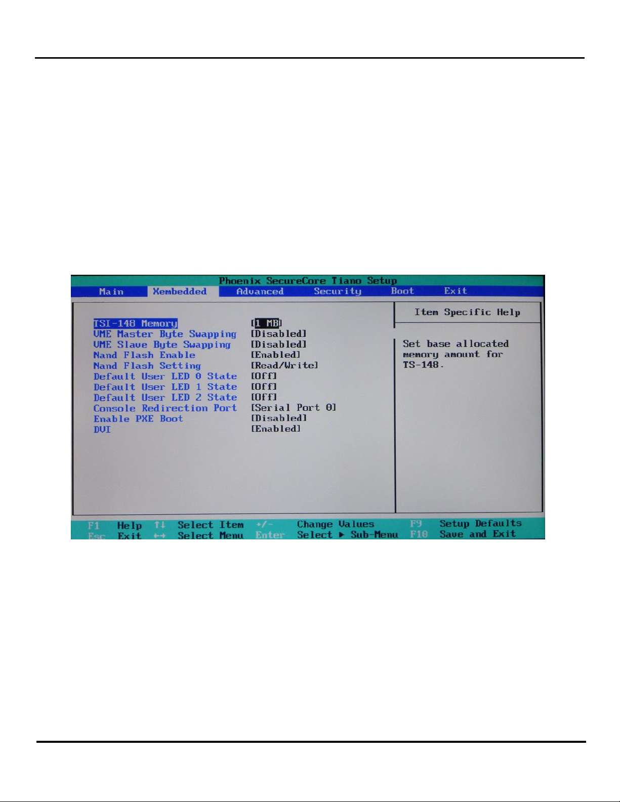
XVME-6300 Xembedded Bios Settings
The BIOS System setup Utility allows you to make modifications to the myriad of BIOS options available for the XVME-
6300. In order to enter setup, you press <F2> several times while it is booting up. Included in the System Utility is a
setup page specifically to configure custom Acromag settings. It is called Xembedded and it is the second page in the
BIOS Setup page as shown below.
TSI-148 Memory
The first option of the Acromag menu is to allow a base allocated memory amount for the TSI-148. The default
memory allocated for the TSI-148 is the smallest available option of 1MByte. This was also the only option in
previous versions of the BIOS and is also therefore selected as the default to maintain compatibility. The other
available sizes are 4MBytes, 8MBytes, 16MBytes, 32MBytes, 64MBytes, and 128MBytes as shown below. Please
note that this will impact the amount of free memory available to the Operating System.

XVME-6300 6U VME Intel i7 Core Processor Board
Acromag, Inc. Tel: 248-295-0310
- 5 -
www.acromag.com
VME Master Byte Swapping
This option on the Acromag menu defines whether to Enable or Disable Master Byte Swapping in the TSI-148
hardware.
VME Slave Byte Swapping
This option on the Acromag menu defines whether to Enable or Disable Slave Byte Swapping in the TSI-148
hardware.
Nand Flash Enable
This option on the Acromag menu defines whether to Enable or Disable the 8GByte SSD hard drive built into the
system.
Nand Flash Setting
This option on the Acromag menu defines whether to allow a user to Read and Write to the on-board hard
8GByte SSD hard drive built into the system. Please note that this option will be ignored if you selected Disable
in the Nand Flash Enable setting.
The Default User LED 0 State, Default User LED 1 State, and Default User LED 2 State
Defines whether or not the specified LED will be On or Off during the power up sequence. These LEDS are
labelled as USR0, USR1, and USR2 on the board as shown below.
XVME-6300 6U VME Intel i7 Core Processor Board
Acromag, Inc. Tel: 248-295-0310
- 6 -
www.acromag.com
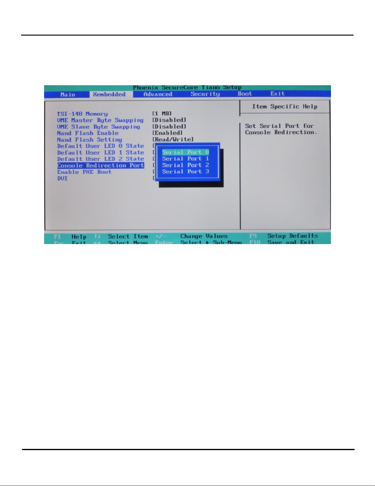
Console Redirection Port
This option selects the serial port that will be used for Console Redirection Port. The available options are Serial
Port 0 to Serial Port 3.
Please note that this only selects the Serial Port and does not actually Enable or Disable Console Redirection.
Enable PXE Boot
This option toggles whether or not the system will be booting from a network server.
DVI
This last option toggles whether or not the on-board DVI port will be Enabled or Disabled.

XVME-6300 6U VME Intel i7 Core Processor Board
Acromag, Inc. Tel: 248-295-0310
- 7 -
www.acromag.com
Operational Block Diagram
Environmental Specifications
ENVIRONMENTAL SPECIFICATION
OPERATING
NON-OPERATING
THERMAL
Air-cooled
610E
620LE
620UE
Extended air-cooled
610E
620LE
620UE
Conduction-cooled
All
Air-cooled
0° to 55°C1w/ 200 lfm airflow
0° to 65°C1w/ 200 lfm airflow
0° to 70°C1w/ 200 lfm airflow
Extended air-cooled
-20° to 60°C2w/ 200 lfm airflow
-20° to 70°C2w/ 200 lfm airflow
-20° to 75°C2w/ 200 lfm airflow
Conduction-cooled
-40° to 85°C3
(measured at board/heatsink rail)
Air-cooled
-40° to 85°C
Extended air-cooled
-40° to 85°C
Conduction-cooled
-55° to 105°C

XVME-6300 6U VME Intel i7 Core Processor Board
Acromag, Inc. Tel: 248-295-0310
- 8 -
www.acromag.com
HUMIDITY
20% - 80% RH, non-condensing4
SHOCK
30 g peak acceleration, 11msec
duration4
50 g peak acceleration, 11 msec
duration4
VIBRATION
5 - 2000 Hz
0.015” (0.38mm) peak-to-peak
displacement, 2.5 g maximum
acceleration4
0.030” (0.76mm) peak-to-peak
displacement, 5 g maximum
acceleration4
EMISSIONS
EN 55022
IMMUNITY
EN 50082-2
1Designed to meet these temp specifications regardless of system utilization (without PMC/XMC installed). Lesser system utilization and/or higher airflow may allow
higher operating temp, although in no case should 85°C be exceeded. CPU temp should be closely monitored for max junction temp of 105°C using a program such as
Argus Monitor if exceeding the temps stated here.
2Every board tested to ensure these temp specifications regardless of system utilization (without PMC/XMC installed). Lesser system utilization and/or higher airflow
may allow higher operating temp, although in no case should 85°C be exceeded. CPU temp should be closely monitored for max junction temp of 105°C using a
program such as Argus Monitor if exceeding the temps stated here.
3Every board tested to ensure these temp specifications. Tested under Windows 7 with Passmark BurnInTest version 5.0, running CPU, Memory, and 3D Graphics
tests simultaneously. During application testing CPU temp should be closely monitored for max junction temp of 105°C using a program such as Argus Monitor if
exceeding measured rail temp of 70°C (thermocouple inside provided heatsink hole).
4Designed to comply with Humidity, Shock and Vibration.
Hardware Specifications
CHARACTERISTIC
SPECIFICATION
POWER
Intel® i7-610E Processor (8GB)
Intel® i7-620LE Processor (8GB)
Intel® i7-620UE Processor (4GB)
+5V: 9.1A (typical); 12.8A (maximum)
+5V: 7.5A (typical); 10.8A (maximum)
+5V: 6.5A (typical); 9.4A (maximum)
VOLTAGE
+5V, +12V, -12V; all +5%/-2.5% (Only +5VDC required)
CPU SPEED
Intel® i7-610E Processor
Intel® i7-620LE Processor
Intel® i7-620UE Processor
2.53 GHz, dual-core
2.0 GHz, dual-core
1.06 GHz, dual-core
ONBOARD MEMORY
Intel® i7-610E Processor
Intel® i7-620LE Processor
Intel® i7-620UE Processor
8GB dual channel DDR3 ECC @ 1066 MHz
4GB or 8GB dual channel DDR3 ECC @ 1066 MHz
4GB dual channel DDR3 ECC @ 800 MHz
GRAPHICS CONTROLLER
Intel® Integrated HD Graphics

XVME-6300 6U VME Intel i7 Core Processor Board
Acromag, Inc. Tel: 248-295-0310
- 9 -
www.acromag.com
2048 x 1536 max resolution, 32-bit color max (VGA)
1920 x 1200 max resolution, 32-bit color max (DVI-D)
ETHERNET CONTROLLER
Intel® 82580EB Quad Port 10/100/1000Base-TX Gigabit Ethernet
INTEGRATED SATA-300 CONTROLLER
SATA0 and SATA1 via P2
INTEGRATED NAND FLASH SSD
8GB on SATA4
ON-BOARD SATA DRIVE
One 1.8" SSD drive on SATA2 via optional XBRD-9050 module
PMC SITE
On board 133MHz/64 Bit PMC/PCI-X
PMC 1: front I/O and full rear I/O Access via P0.
PMC 2: front I/O and limited (Pins 1-28) rear I/O Access via P2
Sites are 3.3V interface level
STEREO AUDIO
IDT 92HD81Bx HDA CODEC
Line Level Stereo Input and Output via P2
USB
Two USB 2.0 via Front panel
Two USB 2.0 via P2
Two USB 2.0 via optional XBRD-9050 module
SERIAL PORTS
16550 compatible (4)
Com 1 and Com2 via P2 (RS-232or RS-422/485 selectable)
Com 4 via front panel connector (RS-232 only)
Com 3 via optional XBRD-9050 module ( RS-232 only)
REGULATORY COMPLIANCE
European Union –CE;3
Electromagnetic Compatibility - 89/336/EEC
RoHS Compliant

XVME-6300 6U VME Intel i7 Core Processor Board
Acromag, Inc. Tel: 248-295-0310
- 10 -
www.acromag.com
VMEbus Specification
VMEbus Compliance
Complies with VMEbus Specification ANSI/VITA 1–1994
2eVME and 2eSST protocols to bring support for higher bandwidth
A32/A24/A16:D64/D32/D16(EO) DTB Master
A32/A24/A16:D64/D32/D16(EO) DTB Slave
R(0-3) Bus Requester
Interrupter I(1)-I(7) DYN
IH(1)-IH(7) Interrupt Handler
SYSCLK and SYSRESET Driver
PRI, SGL, RRS Arbiter
RWD, ROR bus release
Ordering Information
XVME-6300-ABCD-LF
A = CPU
2 = 1.06 GHz i7-620UE
3 = 2.0 GHz i7-620LE
4 = 2.53 GHz i7-610E
B = THERMAL, P0
1 = Air Cooled, VME handles, w/ P0
2 = Air Cooled, VME handles, no P0
5 = Conduction, w/ P0
6 = Conduction, no P0
C = MEMORY
4 = 4Gb memory
8 = 8Gb memory
D = EXTENDED TEMPERATURE
Blank = Standard temperature
E = Extended temperature
LF = SOLDER
LF –Lead-free solder

XVME-6300 6U VME Intel i7 Core Processor Board
Acromag, Inc. Tel: 248-295-0310
- 11 -
www.acromag.com
Installation and Setup
Board Layout
This chapter provides information on configuring the XVME-6300 modules. It also provides information on installing
the XVME-6300 into a backplane.
Fig. 2-1 shows the jumper, switch and connector locations on the XVME-6300

XVME-6300 6U VME Intel i7 Core Processor Board
Acromag, Inc. Tel: 248-295-0310
- 12 -
www.acromag.com
Jumper and Switch Settings
The following section describes the XVME-6300 jumpers and switches, their default positions and their functions.
ORBGND
1-2 (default)
ORB GND TIED TO DIGITAL GND
2-3
ORB GND ISOLATED
CS_PGM
1-2 (default)
NORMAL OPERATION
2-3
FACTORY USE ONLY
This jumper must be in the 1-2 position for normal operation. The XVME-6300 will not boot with this jumper in 2-3
position.
RTCRST
1-2 (default)
NORMAL OPERATION
2-3
CLEAR CMOS/RTC
To clear CMOS memory, briefly move this jumper to position 2-3. Be sure to move it back to position 1-2 before
reapplying power.
FPRST
1-2 (default)
FRONT PANEL BUTTON RESETS SYSTEM (AND ALSO
VME IF SW1-3 IS ON)
2-3
NO PUSHBUTTON RESET
In position 1-2, the front panel reset button will reset the XVME-6300 and also reset the VME interface if SW1-3 is
ON. In position 2-3, the front panel button will not cause any resets.
ME_DIS
1-2 (default)
NORMAL OPERATION
2-3
FACTORY USE ONLY
This jumper must be in position 1-2 for normal operation. Position 2-3 is used when updating the ME Engine portion
of the System Flash. Only use this position if instructed by Acromag Support.
VIDSEL
1-2 (air default)
VGA ON FPANEL CONN
2-3 (conduction default)
VGA ON P2 CONN
In position 1-2, the VGA display is available on the front panel connector.
In position 2-3, the VGA display is available on the P2 connector.

XVME-6300 6U VME Intel i7 Core Processor Board
Acromag, Inc. Tel: 248-295-0310
- 13 -
www.acromag.com
COM1MD
1-2 (default)
COM1 RS-232
2-3
COM1 RS-422/485
In position 1-2, the COM1 serial port uses the RS-232 protocol.
In position 2-3, the COM1 serial port uses the RS-422/485 protocols.
COM2MD
1-2 (default)
COM2 RS-232
2-3
COM2 RS-422/485
In position 1-2, the COM2 serial port uses the RS-232 protocol.
In position 2-3, the COM2 serial port uses the RS-422/485 protocols.
VCFG1
1-2 (default)
SFAILEN bit default = 1
2-3
SFAILEN bit default = 0
The Tsi148 System Failure Enable (SFAILEN) bit controls the assertion of the Tsi148 System Fail Output (SFAILO)
signal. The only exception to this is when the Auto Slot ID method of assigning the CR/CSR base address is being
implemented.
The initial value of the SFAILEN bit can be configured at power-up reset through the VCFG1 jumper. Additionally, a
value can be programmed by software in the Control and Status register.
VCFG2
1-2 (default)
VME SYSFAIL AUTO NEGATED
2-3
VME SYSFAIL NOT AUTO NEGATED
The System Failure Auto Slot ID (SFAILAI) bit is used when the Auto Slot ID protocol is enabled in the system to
assign the CR/CSR base address.
When Auto Slot ID is used to assign the CR/CSR base address, the SFAILAI bit is set by the assertion of the SRSTI_
signal. The SFAILAI bit must be cleared in order for Tsi148’s System Fail Output (SFAILO) signal to be negated. SFAILO
is automatically negated if the VCFG2 jumper is in the 1-2 position. Otherwise SFAILO is negated when software
clears the SFAILAI bit in the VCTRL register.
The initial value of the SFAILAI bit can be configured at power-up reset through the SFAILAI_AC power-up option or
a value can be programmed by software in the SFAILAI bit in the VMEbus Control register (VCTRL).

XVME-6300 6U VME Intel i7 Core Processor Board
Acromag, Inc. Tel: 248-295-0310
- 14 -
www.acromag.com
VCFG3
1-2 (default)
VME AUTO SLOT ID ENABLED
2-3
VME AUTO SLOT ID DISABLED
The Auto Slot ID Enable (ASIDEN) feature is controlled through the VCFC3 jumper. The ASIDEN feature allows the
CR/CSR base address to be configured using the Auto Slot ID protocol.
VCFG4
1-2 (default)
VME GEOGRAPHICAL SLOT ID ENABLED
2-3
VME GEOGRAPHICAL SLOT ID DISABLED
The Geographic Slot ID Enable function initializes the CR/CSR base address register using the VMEbus GA signals.
The Geographic Slot ID Enable feature allows a board to come out of reset with the CR/CSR registers visible from the
VMEbus and the base address of the CR/CSR is determined by the VMEbus GA signals.
If the VCFG4 jumper is in the 2-3 position the CR/CSR enable bit and CBAR bits are cleared. If the VCFG4 jumper is in
the 1-2 position, the CR/CSR enable bit is set and the CBAR bits 7 to 3 are set to the inverted value of the VMEbus
geographic address signals. When the SRSTI_ signal is asserted, the CR/CSR EN bit and the CBAR bits are loaded with
the power-up option reset values.
The initial value of the CR/CSR Enable bit in the CR/CSR Attribute (CRAT) register and CBAR bits in the CR/CSR Base
Address (CBAR) register can be configured at power-up reset using the Geographic Slot ID Enable function.
SW1
1:2
OFF:OFF
SYSCON AUTO-DETECT
OFF:ON
SYSCON ENABLED
ON:OFF
SYSCON DISABLED
ON:ON
SYSCON DISABLED
3
ON
LOCAL RESET DRIVES VME SYSRST#
OFF
LOCAL RESET DOES NOT DRIVE VME SYSRST#
4
ON
VME SYSRST# DRIVES LOCAL RESET
OFF
VME SYSRST# DOES NOT DRIVE LOCAL RESET
SW1-1 and SW1-2 control the Auto System Controller (SYSCON) feature.

XVME-6300 6U VME Intel i7 Core Processor Board
Acromag, Inc. Tel: 248-295-0310
- 15 -
www.acromag.com
When SW1-1 and SW1-2 are both OFF, The SVME-6300 uses the BG3IN_ signal to enable a board to determine if it is
in VMEbus slot 1. If the board is in VMEbus slot 1, the BG3IN_ signal is low and the SCON function is enabled. If the
board is not in VMEbus slot 1, the BG3IN_ signal is high and the SCON function is disabled.
SW1-3 controls whether a local board reset drives out onto the VMEbus. When SW1-3 is ON the VME SYSRST# line
will be driven low to reset the VMEbus whenever the XVME-6300 is reset locally. When SW1-3 is OPEN the VMEbus
will not be reset.
SW1-4 controls whether the VMEbus can reset the XVME-6300. When SW1-4 is ON the XVME-6300 will be reset
when the VME SYSRST# signal is driven low. When SW1-4 is OFF the XVME-6300 will not respond to a VME SYSRST#.
Connectors
This section provides pin outs for the non-standard connectors on the XVME-6300. Refer to the EMC warning at the
beginning of this manual before attaching cables.
FPANEL
The FPANEL connector ports (USB1, USB2, COM4 and VGA) can be accessed through standard connectors by
using the supplied FPANEL dongle cable (P/N 201157). Note that the DB-9 serial connector on this dongle
cable is wired as a DTE port.
1
GND
2
USB Port 0 +
3
USB Port 0 -
4
GND
5
+5V USB POWER
6
VGA DDC DATA
7
VGA RED
8
VGA GREEN
9
VGA BLUE
10
GND
11
USB Port 1 +
12
USB Port 1 -
13
GND
14
+5V VGA POWER
15
VGA DDC CLK
16
GND RED
Table of contents


