ACS GWA-250 User manual

Technical manual BA 0509
Si
g
nal converter
GWA – 250 / GWAP-250
Limit value switch
for limit value supervision of
electrical signals
Evaluable Signals
Standard signals 0...10V / 0...20mA resp. 4...20mA
Temperature resistor Pt100 from –50°C...+650°C
Two limit value relays with different operation modes
Safety function with minimum or maximum safety
Double limit value function – two separated limit values
Two-position-control function – a limit value with hysteresis
Configurable switching delay
Simple operation per key coding switch for adjusting the
limit values from 0...99% of the signal range in steps of 1%
Integrated measurand transducer supply
Version with remote control available
Wide range power supply from 20 to 253V AC and DC
Lauterbachstr. 57 – 84307 Eggenfelden – Germany
Tel: +49 8721/9668-0 – Fax: +49 8721/9668-30

GWA – 250
page 2 of 8
Index
Order code ..................................................................................................................... 2
Application ..................................................................................................................... 3
Function ..................................................................................................................... 3 / 4
Safety notes ................................................................................................................... 5
Installation ...................................................................................................................... 5
Maintenance ................................................................................................................... 5
Repair ............................................................................................................................. 5
Electrical connection .................................................................................................... 6
Operation and display elements .................................................................................... 7
Technical data ............................................................................................................... 8
Order code
GWA – 250 – U0 Version input signals 0...10V / 0...20mA resp. 4...20mA with on-site control
GWAS – 250 – U0 Version input signals 0...10V / 0...20mA resp. 4...20mA with remote control
GWAP – 250 – U0 Version input signal Pt100 from –50°C...+650°C with on-site control
GWAPS – 250 – U0 Version input signal Pt100 from –50°C...+650°C with remote control

GWA – 250
page 3 of 8
Application
The limit value switch GWA – 250 is used for supervising electrical standard signals 0...10V / 0...20mA resp.
4...20mA or temperature resistors Pt100 regarding transgression resp. underrun of limit values.
The device allows it, additionally to continuous measurements, to set up to two switching limits without the need
for additional measurement devices.
The version GWA – 250 is suitable for supervision of supply and control voltages, e.g. in the water and waste
water industry for filling level monitoring and pump control (e.g. 15% pump on, 95% pump off).
The version GWAP – 250, for connection of a temperature resistor Pt100, can be used for supervision of
process temperatures in all fields of industry.
Alternatively to the on-site operation, where the key coding switches for setting the switching limit are integrated
in the device, the version S is available, where the key coding switches can be installed separately from the
device, using them as remote control. These are suitable for the installations into control cubicle doors resp.
front panels.
Function
Measuring principle
Version GWA – 250 / GWAS – 250
The connected electrical standard signal 0...10V / 0...20mA resp. 4...20mA is compared by the evaluation circuit
with the set limit value at the key coding switches in % of the nominal signal range (10V / 20mA / 16mA), with
reference to the respective signal zero value (0V / 0mA bzw. 4mA).
Examples:
At standard signal 0...10V the setting 50% equals a signal voltage of 5V
At standard signal 0...20mA the setting 50% equals a signal current of 10mA
At standard signal 4...20mA the setting 50% equals a signal current of 8mA (50% of 16mA) + 4mA = 12mA
The connected signal device at the input can be powered by the integrated measurand transducer supply.
Version GWAP – 250 / GWAPS – 250
The voltage drop at the connected temperature sensor Pt100 is compared by the evaluation circuit with the set
limit value at the key coding switches in % of the set temperature signal range (30K / 50K / 100K / 600K), with
reference to the set signal zero value (-50°C / 0°C / +50°C).
Examples:
At zero value –50°C and range 100K the setting 50% equals a temperature of –50°C + 50K = 0°C
At zero value 0°C and range 600K the setting 50% equals a temperature of 0°C + 300K = 300°C
At zero value +50°C and range 30K the setting 50% equals a temperature of +50°C + 15K = 65°C
The connected Pt100 in 2-wire resp. 3-wire technology is supplied be an internal constant current source and is
supervised for wire break or short circuit.
Signal evaluation
The transgression resp. underrun of the set limit value causes the switching of the relay resp. the relays
depending on the configured safety function (minimum resp. maximum safety) resp. operation function (double
limit value function resp. two-position-control function).
The switching state of the relays is indicated at the front side of the device by two red LED’s.
Switching delay
In some applications it is necessary to compensate heavy signal fluctuations that may be produced by mixing
machines or at fill-in resp. emptying of containers, to avoid spurious switching actions.
Two switches inside the device allows the configuration of a switching delay of 0,4 s or 4 s, separately for each
output relay, at activation and deactivation of the respective output relay.

GWA – 250
page 4 of 8
Safety function
The safety function defines the operation principle of the output relays.
Maximum safety: The relay switches off, if the switching level is transgressed,
or the power supply fails.
Minimum safety: The relay switches off, if the switching level is underrun,
or the power supply fails.
For both output relays, A and B, the safety function can be set separately.
This can be carried out by two switches, one per relay, inside the device.
Two-position-control ∆s
The activation of the two-position-control is made by a switch inside the device.
Two-position-control with minimum safety Two-position-control with maximum safety
The set limit value A equals the switching value and the limit value B equals the switch back value.
At two-position-control the safety function must be set identically for both output relays.

GWA – 250
page 5 of 8
Safety notes
Each person that is engaged with inauguration and operation of this device, must have read and
understood this technical manual and especially the safety notes.
Installation, electrical connection, inauguration and operation of the device must be made by a qualified
employee according to the informations in this technical manual and the relevant standards and rules.
The device may only be used within the permitted operation limits that are listed in this technical manual.
Every use besides these limits as agreed can lead to serious dangers.
The device meets the legal requirements of all relevant EC directives.
Installation
The device is conceived for vertical installation on a standard fastening rail acc. to DIN EN 60715 TH 35-7,5
resp. TH35-15.
DIN EN 60715 TH 35-7,5
DIN EN 60715 TH35-15
The device must be installed protected against dust and humidity, e.g. in control stations or in a suitable
protection housing with a minimum protection classification IP55 acc. to DIN EN 60529.
The devices must be installed wheather and stroke protected, ideally at places without direct solar radiation.
This is especially important in warm climatic regions.
At the version S, with remote control, the remote control is suitable for installation into control cubicle doors or
front panels.
The necessary cut dimensions are (W x H) 24 x 14mm. The optimum wall thickness is 0,7mm.
Maintenance
The device is free of maintenance.
Repair
A
repair may only be carried out by the manufacturer. When sending back the device, add a note with the description of the
error and the application.

GWA – 250
page 6 of 8
Electrical connection
The electrical connection of the device must be carried out according to the respective country specific
standards. Incorrect installation or adjustment could cause applicationally conditioned risks.
Power supply input, measuring input and relay output channels are safe galvanically isolated from each other.
This is also valid for both relay output channels among each other.
Connection of the signaling transmitter resp. measuring transducer – measuring inputs
For the two, three or four-wire connection cable between the limit value switch and the signaling transmitter
resp. measuring transducer a standard installation cable or multi-wire cable for measuring intends with a
maximum of 25 Ωper wire can be used.
The use of a shielded signal cable is recommended, if strong electromagnetic influences could happens, e.g.
due to machines or radio equipment. In that case the shielding of the cable should be connected to earth only at
the side of signaling transmitter resp. measuring transducer.
The signal cable should be installed separated from power leading wires.
The connected signaling transmitter resp. measuring transducer can be powered by the integrated measuring
transducer supply. The supply is overload and short circuit protected.
The maximum values of the inputs at the limit value switch GWA – 250 (current input maximum 400mA - 30V /
voltage input 50V) must not be transgressed. The current input is equipped with a self resetting fuse.
At activation of the fuse the signal current wire must be disconnected for app. 5 seconds.
If more than two limit values to a standard signal (V / mA) should be evaluated at the limit value switch
GWA – 250, additional devices could be connected in series (mA) resp. in parallel (V).
At a current signal, the signal must be feed to both current inputs (2 – I-In / 1 – GND) in series. At a voltage
signal, the reference terminal (1 – GND) and the signal input (3 – U-In) of the limit value switches must be
connected together.
At the type GWAP – 250 a signal sided (Pt100) device coupling is not possible.
Connection of the signaling and control equipments – relay outputs
Inductive loads at the relay contacts, e.g. auxiliary contactors or magnetic vents may only be used with a free-
wheeling diode or a RC protection circuit to avoid high voltage peaks.
For inauguration it is suggested, to deactivate all connected control devices, to avoid unwanted control
reactions.
Connection of the power supply voltage
Due to the integrated wide range power supply, for connection to supply voltages from 20...253V AC / DC, the
limit value switch is suitable for using in all common energy supply networks.
The connection is reverse polarity protected.
A fuse is integrated internally at the power supply circuit. Due to this the installation of a fine protection is not
necessary.

GWA – 250
page 7 of 8
Operation and display elements
Function indicator
ON green LED ready status, power supply voltage on
A red LED output relay A switched on
B red LED output relay B switched on
Key coding switch
For setting the limit value from 0...99% of the configured signal range in steps of 1%.
At two-position-control ∆s the limit value A represents the switching value and the limit value B the switching back value.
Configuration switches
The configuration of the input signal range as well as the relay functions is made per dip switches inside the housing.
Dangerous voltage
Ensure a safe switching off the supply voltage when opening the housing
For configuration release the upper housing part at top and bottom side behind the terminals by using a screwdriver and pull
it out of the housing. Drop-in pin's avoid a complete pulling out. Following the respective dip switches can be set according to
the desired functions to ON or OFF.
Relay functions switcher block SB1
Switch 1, 2, 5, 6 (SB1) Safety function
switching state S1 switching state S2 safety function
ON OFF channel B – minimum safety
OFF ON channel B – maximum safety
switching state S5 switching state S6 safety function
ON OFF channel A – minimum safety
OFF ON channel A – maximum safety
Switch 3, 7 (SB1) switching delay
switch switching state ON switching state OFF
3 channel B – 4 seconds channel B – 0,4 seconds
7 channel A – 4 seconds channel A – 0,4 seconds
Switch 4 (SB1) operation function
switch switching state ON switching state OFF
4 two-position-control ∆s double limit value switch function
Input signal range GWA – 250 switcher block SB2
Switch 1 (SB2) measuring range – only at GWA – 250
switch switching state ON switching state OFF
1 input signal 4...20mA input signal 0...10V / 0...20mA
Input signal range GWAP – 250 switcher block SB2 / SB3
Switch 2, 3 (SB2) measuring range signal zero value – only at GWAP – 250
switching state S2 switching state S3 signal zero value
ON ON zero value – 50°C
OFF ON zero value 0°C
OFF OFF zero value + 50°C
Switch 1, 2, 3 (SB3) measuring range signal range – only at GWAP – 250
switching state S1 switching state S2 switching state S3 signal range
ON ON ON 30 Kelvin
ON OFF ON 50 Kelvin
OFF OFF ON 100 Kelvin
OFF OFF OFF 600 Kelvin
Limit value channel B
2-digit
key coding switch
Function indicato
r
3 LED’s for indication
of operating states
Limit value channel
A
2-digit
key coding switch Configuration switch
inside the housing

GWA – 250
page 8 of 8
Technical data
Auxiliary power supply
Permitted supply voltage: 20 V to 253 V AC / DC 48...62 Hz,reverse polarity protected
Power consumption: ≤2,5 VA / 1,75 W
Overvoltage category: II acc. to DIN EN 61010-1
Protection classification: II double or reinforced insulation
Isolation voltage: 4kV~ Auxiliary power to relay outputs to signal inputs
Galvanic isolation: All supply, input and output channels among each other as well as both relay outputs
from each other are safe galvanically isolated.
Relay outputs
Function: 2x potential-free changeover contact
Switching power of the contacts: U~ maximum 253 V AC
I~ maximum 6 A AC (maximum switch-on current 10A)
P~ maximum 1500 VA at ohmic load / 300 VA at cos ≥0,7
at U- maximum I- maximum P-
30 V 6 A 180 W
110 V 0,3 A 33 W
220 V 0,12 A 26,4 W
Minimum switching load: ≥50mW (0,5 V / 1 mA)
Switching cycles: ≥100.000 switching cycles at maximum contact load
Delay time: ≤0,4s ±0,1s resp. ≤4s ±1s
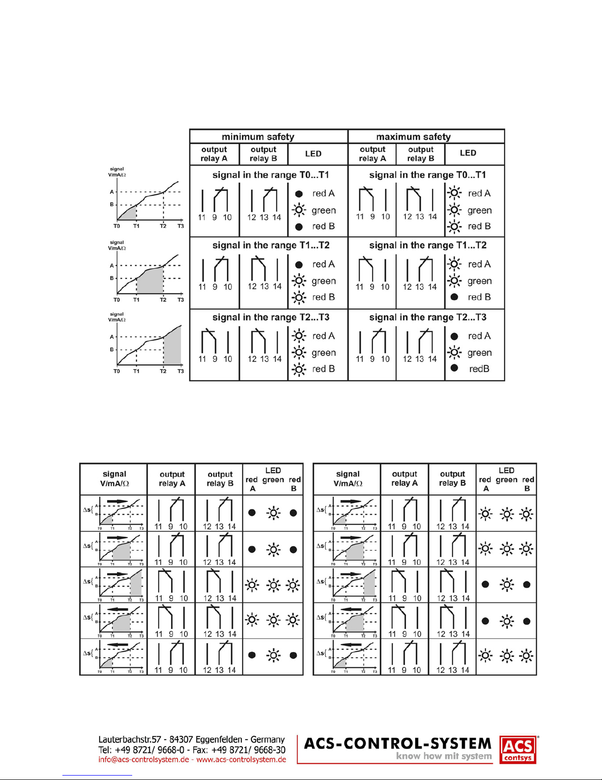
Switching hysteresis 0,5% ±0,2% / at two-position-control ∆s: limit value A – limit value B
Signal input GWA – 250
Direct voltage: 0…10 V / maximum 50V / input resistance 100kΩ
Direct current: 0…20mA / 4…20mA / maximum 400mA at 30V – self resetting fuse
Input resistance 50Ω+ 0,2V
Measuring deviation: ≤0,4% of nominal measuring range
Temperature deviation: ≤0,2% / 10 K of nominal measuring range
Measurand transmitter supply: overload and short circuit protected
3-wire-sensor: ≥21,2V at 20mA ≥20,7V at 27,5mA min. 27,5mA / max. 25V
2-wire-sensor: ≥20,0V at 20mA ≥19,0V at 27,5mA min. 27,5mA / max. 25V
Signal input GWAP – 250
Temperature resistor Pt100: 3-wire- / 2-wire-measuring, resistance linear, measuring current 2 x 0,515mA ±10µA
Measuring range: Zero value: –50°C, 0°C +50°C / range: 30 Kelvin, 50 Kelvin, 100 Kelvin, 600 Kelvin
Measuring deviation: ≤0,4% (at zero value –50 / +50°C end value error ≤2%) of nominal meas. range
Temperature deviation: ≤0,2% / 10 K of nominal measuring range
Wire resistance: ≤40 Ωper wire
Error supervising: At wire break / short circuit of one or multiple Pt100 connection wires the output
relays are switched off (at safety function minimum safety). At short circuit resp.
wire link between terminals 1 and 2 the device operates in 2-wire-measuring
Materials
Connection housing: PA – polyamide
Terminal housing: PA – polyamide
Sticker: PE – polyester
Connection terminals
Number: 3 resp. 4 terminal blocks with each 4 terminals, everlasting screws
Connection cross-section: maximum 1 x 2,5 mm or 2 x 1,5 mm
Housing style
Housing: Series installation housing, 22,5mm wide
Weight: 100 g
Environmental conditions
Environmental temperature: Single installation – 40°C...+85°C
Series installation – 40°C...+70°C
Climatic classification: 3K3 resp. 3M2 DIN EN 60721-3-3
Protection classification: IP20 DIN EN 60529
EM – compatibility: emission DIN EN 61326-1 operation device class B
immunity DIN EN 61326-1 industrial range
This manual suits for next models
1
Table of contents
Other ACS Switch manuals
Popular Switch manuals by other brands

BEP
BEP MARINCO PRO INSTALLER 771-SFD manual

TRENDnet
TRENDnet TE100-S810Fi - Switch Specifications

American Megatrends
American Megatrends MegaRAC K1 quick hardware installation guide

LevelOne
LevelOne GEP-0950 Quick installation guide

H3C
H3C S7502 installation manual

D-Link
D-Link DGS-1210-52/FL Quick installation guide