Acson international F Series User manual
INSTALLATION MANUAL
CEILING CONCEALED
CHILLED WATER FAN COIL UNIT
(F SERIES)
IM-CCFWD-0117(1)L-ACSON
Part No.: R08019046054A
IM-CCFWD-0117(1)L-ACSON.indb iIM-CCFWD-0117(1)L-ACSON.indb i 5/31/2017 10:14:55 AM5/31/2017 10:14:55 AM

IM-CCFWD-0117(1)L-ACSON.indb iiIM-CCFWD-0117(1)L-ACSON.indb ii 5/31/2017 10:14:55 AM5/31/2017 10:14:55 AM
1-1
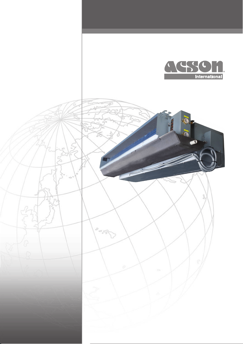
OUTLINE AND DIMENSIONS
Indoor Unit: Ceiling Concealed Fan Coil Unit F Series
LEFT PIPING All dimensions are in mm
KE
13DK
32118348
31
KC
KB
140
KA32
20
552
129 20
11
143
87 71
247
186
31
RIGHT PIPING All dimensions are in mm
KE
KD
KC
KB
KA
31
321183
48
31
140
32
552
11
186
87 71
31
247
20
20 129
143
Dimension
Model KA KB KC KD KE
06/09FWD 619 477 437 440 501
12/15FWD 870 726 687 690 751
18FWD
1060 916 877 880 941
24FWD
1390 1246 1207 1210 1271
30FWD
1600 1456 1417 1420 1481
Original Instruction English
IM-CCFWD-0117(1)L-ACSON.indb 1IM-CCFWD-0117(1)L-ACSON.indb 1 5/31/2017 10:14:55 AM5/31/2017 10:14:55 AM

1-2
INSTALLATION MANUAL
This manual provides the procedures of installation to ensure a safe and good standard of operation for the air conditioner unit.
Special adjustment may be necessary to suit local requirement.
Before using your air conditioner, please read this instruction manual carefully and keep it for future reference.
This appliance is intended to be used by expert or trained users in shops, in light industry and on farms, or for commercial
use by lay persons.
This appliance is not intended for use by persons, including children, with reduced physical, sensory or mental capabilities, or
lack of experience and knowledge, unless they have been given supervision or instruction concerning use of the appliance by a
person responsible for their safety.
Children should be supervised to ensure that they do not play with the appliance.
SAFETY PRECAUTIONS
WARNING
• Installation and maintenance should be performed by qualified
persons who are familiar with local code and regulation, and
experienced with this type of appliance.
• All field wiring must be installed in accordance with the
national wiring regulation.
• Ensure that the rated voltage of the unit corresponds to that of
the name plate before commencing wiring work according to
the wiring diagram.
• The unit must be GROUNDED to prevent possible hazard due
to insulation failure.
• All electrical wiring must not touch the refrigerant piping, or
any moving parts of the fan motors.
• Confirm that the unit has been switched OFF before installing
or servicing the unit.
• Disconnect from the main power supply before servicing the
air conditioner unit.
• DO NOT pull out the power cord when the power is ON. This
may cause serious electrical shocks which may result in fire
hazards.
• Keep the indoor and outdoor units, power cable and
transmission wiring, at least 1m from TVs and radios, to
prevent distorted pictures and static. {Depending on the type
and source of the electrical waves, static may be heard even
when more than 1m away}.
CAUTION
Please take note of the following important points when
installing.
• Ensure that the drainage piping is connected properly.
If the drainage piping is not connected properly, it may
cause water leakage which will dampen the furniture.
• Ensure that the unit’s panel is closed after service or
installation.
Unsecured panels will cause the unit to operate noisily.
• Sharp edges and coil surfaces are potential locations which
may cause injury hazards. Avoid from being in contact with
these places.
• Before turning off the power supply set the remote controller’s
ON/OFF switch to the “OFF” position to prevent the nuisance
tripping of the unit. If this is not done, the unit’s fans will start
turning automatically when power resumes, posing a hazard to
service personnel or the user.
• Do not install the units at or near doorway.
• Do not install the units at area like hot spring or oil refinery
plant where sulphide gas exists.
• Do not operate any heating apparatus too close to the air
conditioner unit or use in room where mineral oil, oil vapour or
oil steam exist, this may cause plastic part to melt or deform as a
result of excessive heat or chemical reaction.
• When the unit is used in kitchen, keep flour away from
going into suction of the unit.
• This unit is not suitable for factory used where cutting oil
mist or iron powder exist or voltage fluctuates greatly.
• Ensure the color of wires of the outdoor unit and the
terminal markings are same to the indoors respectively.
• IMPORTANT : DO NOT INSTALL OR USE THE AIR
CONDITIONER UNIT IN A LAUNDRY ROOM.
• Don’t use joined and twisted wires for incoming power
supply.
• The equipment is not intended for use in a potentially
explosive atmosphere.
NOTICE
Disposal requirement
Your air conditioning product is marked with this symbol. This means that electrical and electronic products shall not be mixed
with unsorted household waste.
Do not try to dismantle the system yourself: the dismantling of the air conditioning system, treatment of the refrigerant, of oil and of
other parts must be done by a qualifi ed installer in accordance with relevant local and national legislation.
Air conditioners must be treated at a specialized treatment facility for re-use, recycling and recovery. By ensuring this product
is disposed of correctly, you will help to prevent potential negative consequences for the environment and human health. Please
contact the installer or local authority for more information.
Batteries must be removed from the remote controller and disposed of separately in accordance with relevant local and national
legislation.
IM-CCFWD-0117(1)L-ACSON.indb 2IM-CCFWD-0117(1)L-ACSON.indb 2 5/31/2017 10:14:55 AM5/31/2017 10:14:55 AM

1-3
English
INSTALLATION OF THE INDOOR UNIT
The indoor unit must be installed such that there is
no short circuit of the cool discharge. Respect the
installation clearance.
Do not put the indoor unit where there is direct
sunlight on unit. The location is suitable for piping
and drainage and it must have a large distance
between a door and unit.
In cases where the temperature above the ceiling
might reach 30°C or the humidity RH80%, reinforce
the drain pan insulation (10mm or thicker) or adding
secondary Drain Pan. Condensation may form on
the surface of the insulating material.
Provide clearance for servicing ease and optimal air
flow as shown in the diagram.
Ceiling Concealed Mounting
• Use the hanger supplied with the unit.
• Make sure that the ceiling is sufficiently strong to
withstand the weight.
300mm* or more
300mm
or more
10mm
Floor
2300mm or more
Ceiling
* Can be smaller than 300mm if ceiling is removable.
Field supply
Washer for hanger bracket
(attached)
Tighten
Detail A
CAUTION
Do not install the unit at altitude over 2000m for both indoor and outdoor.
Ceiling Concealed Drain Piping Work
DRAIN PIPE
The suggested slope of the
drain pipe is at least 1:50
Insulate securely
10mm (0.39")
• The drain pipe must be installed as shown in the diagram (see diagram above) to avoid damage caused by
leaks and condensation.
• For the best result, keep the piping as short as possible. Slant the piping at an angle to improve the flow.
• Ensure the drain pipe is securely insulated.
• Keep pipes as straight as possible for easy cleaning and to prevent the accumulation of dirt and debris.
• Conduct a water drainage test after the installation is completed. Make sure that the drainage flow is smooth.
• In humid environments, use an extra drain pan to cover the entire area of the indoor unit.
Insulation material
(field supply)
Aluminium tape
(field suppl
y
)
Air outlet side
Air inlet side
See Detail A
Aluminium tape
(field supply)
IM-CCFWD-0117(1)L-ACSON.indb 3IM-CCFWD-0117(1)L-ACSON.indb 3 5/31/2017 10:14:55 AM5/31/2017 10:14:55 AM
1-4
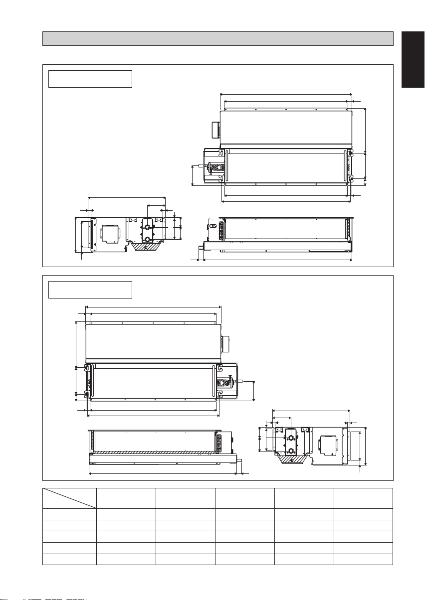
IMPORTANT NOTICE
CORK TAPE FULLY INSTALLED
INSULATION THROUGH OUT CHILLED WATER PIPING
WATER PIPING CONNECTION
• The indoor unit is equipped with water outlet and inlet connection. There is an air-vent that is fitted along
with the connection for air purging.
• 3 way valve is required for cycling off or bypass the chilled water.
• Black steel pipe, closed cell polyurethane pipe and copper tube are recommended in the field installation.
All types of piping and connection must be insulated with closed cell polyurethane to avoid condensation.
• Do not use contaminated or damaged pipe and fitting for installation.
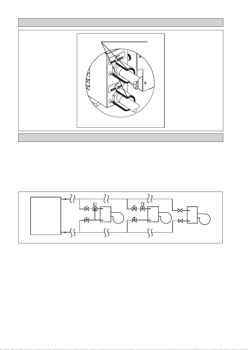
• Some main fitting components are needed in the system to enhance the capacity and ease of service, such as
gate valve, balancing valve, 2 way or 3 way valve, strainer and etc.
Chiller
Gate Valve
Gate Valve
FCU
Three Way Valve Gate Valve
Gate Valve
FCU
Two Way Valve
gnillortnoCdaBgnillortnoCdooG
Gate Valve
Gate Valve
FCU
Worst Controlling
IM-CCFWD-0117(1)L-ACSON.indb 4IM-CCFWD-0117(1)L-ACSON.indb 4 5/31/2017 10:14:56 AM5/31/2017 10:14:56 AM

1-5
English
ELECTRICAL WIRING CONNECTION
06/09/12/15/18/24/30FWD
3UCF2UCF1UCF
FSC
X2
X1
Chiller
FL FM FH N
There must be an all pole
disconnection in the supply mains
with a contact separation of at
least 3mm.
All power line must be from the
same phase.
TH
220-240V/~/50Hz or
208-230V/~/60Hz
TH
220-240V/~/50Hz or
208-230V/~/60Hz
220-240V/~/50Hz or
208-230V/~/60Hz
TH
FSC FSC
NHFMFLFNHFMFLF
L
N
L
N
L
N
FL Fan Low
FM Fan Medium
FH Fan High
N Neutral
FSC Fan Speed Controller
X1, X2, X3 Relay (220~240V, 10A)
TH Thermostat
X3
IMPORTANT: * These values are for information only. They should be checked and selected to comply
with local and/or national codes and/or national codes and regulations. They are also
subject to the type of installation and size of conductors.
** The appropriate voltage range should be checked with label data on the unit. A main
switch or other means for disconnection, having a contact separation in all poles, must
be incorporated in the fixed wiring in accordance with the relevant local and national
legislation.
Model Indoor 06FWD 09FWD 12FWD 15FWD
Voltage Range** Indoor 220V-240V/~/50Hz +
Power Supply Cable Size*
Number of Conductors
mm21.5
5
1.5
5
1.5
5
1.5
5
Recommended Time Delay Fuse* A1111
Model Indoor (CE) 18FWD 24FWD 30FWD
Voltage Range** Indoor 220V-240V/~/50Hz +
Power Supply Cable Size*
Number of Conductors
mm21.5
5
1.5
5
1.5
5
Recommended Time Delay Fuse* A223
Note:
This is a proposed wiring connection. It may change subject to the chiller unit and must comply with the local
and national code and regulations.
IM-CCFWD-0117(1)L-ACSON.indb 5IM-CCFWD-0117(1)L-ACSON.indb 5 5/31/2017 10:14:56 AM5/31/2017 10:14:56 AM
1-6
• All wires must be firmly connected.
• Make sure all the wire do not touch the refrigerant pipings, or any moving parts.
• The power supply cord must be equivalent to H07RN-F which is the minimum requirement.
• Make sure no external pressure is applied to the terminal connectors and wires.
• Make sure all the covers are properly fixed to avoid any gap.
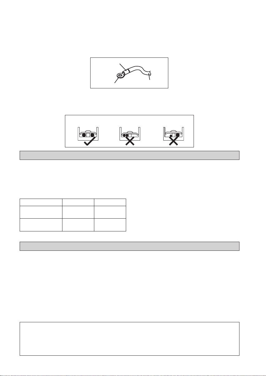
• Use round crimp-style terminal for connecting wires to the power supply terminal block. Connect the wires by
matching to the indication on terminal block. (Refer to the wiring diagram attached on the unit).
Attach insulation sleeve
Round crimp-st
y
le terminal Electric wire
• Use the correct screwdriver for terminal screws tightening. Unsuitable screwdrivers can damage the screw head.
• Over tightening can damage the terminal screw.
• Do not connect wire of different gauge to same terminal.
• Keep wiring in an orderly manner. Prevent the wiring from obstructing other parts and the terminal box cover.
Connect wires of the
same gauge to both side.
Do not connect wires of the
same gauge to one side.
Do not connect wires
of different gauges.
OPERATING RANGE
Operating Limits:
Thermal carrier : Water
Water temperature : 4°C ~ 10°C (Cooling)
Maximum water pressure : 16 bar
Air temperature : (as below)
Cooling Mode
Temperature Ts °C/°F Th °C/°F
Minimum indoor
temperature 19.0 / 66.2 14.0 / 57.2
Maximum indoor
temperature 32.0 / 89.6 23.0 / 73.4
Ts: Dry bulb temperature. Th: Wet bulb temperature.
OVERALL CHECKING
• Ensure that:
1) The unit has been mounted solidly and rigid in
position.
2) The piping and connections are leak-proof after the
charging.
3) Proper wiring has been installed.
• Drainage check
– pour some water into the left side of the drain pan
(the drainage is at the right side of the unit).
• Test run:
1) Conduct a test run on the unit after having perform the
water drainage test and the gas leakage test.
2) Check the following items:
a) Is the electrical plug inserted firmly into the socket?
b) Is there any abnormal sounds from the unit?
c) Is there any abnormal vibrations on the unit or the
d) piping?
e) Is the drainage of water smooth?
• Confirm that:
1) The evaporator blower is running and discharge cool air.
Note:
• The installation guide above covers only the fan coil unit. For installation of outdoor (mini chiller etc)
please refer to the installation guide for such unit.
• The installation of fan coil unit may vary according to the type of outdoor unit.
• Installation must be done by qualified personnel who is familiar with this type of product.
IM-CCFWD-0117(1)L-ACSON.indb 6IM-CCFWD-0117(1)L-ACSON.indb 6 5/31/2017 10:14:56 AM5/31/2017 10:14:56 AM

1-7
English
AIR FILTER SERVICES
Remove air filter to side (Figure 1)
• Remove side air filter cover. (Left or Right side).
• Slide air filter out from filter rail.
Remove air filter to bottom (Figure 3)
• Remove bottom air filter cover.
• Slide and pull down air filter from air filter rail.
Figure 1 Figure 3
Install air filter from side (Figure 2)
• Insert the 1st air filter into the air filter rail.
• Align the 2nd air filter with 1st air filter hook.
• Push the air filter to the end of air filter rail.
• Put back the side air filter cover.
Figure 2
Install air filter from bottom (Figure 4)
• Insert the 1st air filter into the air filter rail.
• Push the air filter to the side.
• Align the 2nd air filter with 1st air filter hook.
• Push the air filter to the end of air filter rail.
• Put back the bottom air filter cover.
Figure 4
Note:
• The steps involved are based on Fan Coil Unit with Right Piping connection.
IM-CCFWD-0117(1)L-ACSON.indb 7IM-CCFWD-0117(1)L-ACSON.indb 7 5/31/2017 10:14:56 AM5/31/2017 10:14:56 AM

1-8
SERVICE AND MAINTENANCE
Service Parts Maintenance Procedures Period
Indoor Air Filter 1. Remove any dust adhering to the filter by using a
vacuum cleaner or wash in lukewarm water (below
40°C) with a neutral cleaning detergent.
2. Rinse the filter well and dry before placing it back onto
the unit.
3. Do not use gasoline, volatile substances or chemicals to
clean the filter.
At least once
every 2 weeks.
More frequently if
necessary.
Indoor Unit 1. Clean any dirt or dust on the grille or panel by wiping
it with a soft cloth soaked in lukewarm water (below
40°C) and a neutral detergent solution.
2. Do not use gasoline, volatile substances or chemicals to
clean the indoor unit.
At least once
every 2 weeks.
More frequently if
necessary.
CAUTION
Avoid direct contact of any coil treatment cleaners on plastic part. This may cause plastic part to
deform as a result of chemical reaction.
TROUBLESHOOTING
For any enquiries on spare parts, please contact your authorized dealer. If any malfunction of the air
conditioner unit is noted, immediately switch off the power supply to the unit. Check the following fault
conditions and causes for some simple troubleshooting tips.
Fault Causes / Action
1. The air conditioner unit does not operate. – Power failure, or the fuse need to be replaced.
– The power plug is disconnected.
– It is possible that your delay timer has been set
incorrectly.
2. The air flow is too low. – The air filter is dirty.
– The doors or windows are open.
– The air suction and discharge are clogged.
– The regulated temperature is not high enough.
3. Discharge air flow has bad odor. – Odors may be caused by cigarettes, smoke
particles, perfume etc. which might have adhered
onto the coil.
4. Condensation on the front air grille of the indoor
unit.
– This is caused by air humidity after an extended
long period of operation.
– The set temperature is too low, increase the
temperature setting and operate the unit at high
fan speed.
5. Water flowing out from the air conditioner unit. – Switch off unit and call local dealer / serviceman.
If the fault persists, please call your local dealer / serviceman.
IM-CCFWD-0117(1)L-ACSON.indb 8IM-CCFWD-0117(1)L-ACSON.indb 8 5/31/2017 10:14:56 AM5/31/2017 10:14:56 AM

IM-CCFWD-0117(1)L-ACSON.indb 9IM-CCFWD-0117(1)L-ACSON.indb 9 5/31/2017 10:14:56 AM5/31/2017 10:14:56 AM

•The manufacturer reserves the right to revise any of the specification and design contain herein at any time without prior
notification.
•All images are for illustration purposes only.
Lot 60334, Persiaran Bukit Rahman Putra 3, Taman Perindustrian Bukit Rahman Putra,
47000 Sungai Buloh, Selangor Darul Ehsan, Malaysia.
IM-CCFWD-0117(1)L-ACSON.indb 10IM-CCFWD-0117(1)L-ACSON.indb 10 5/31/2017 10:14:56 AM5/31/2017 10:14:56 AM
This manual suits for next models
7
Table of contents
Other Acson international Fan manuals

Popular Fan manuals by other brands


Bestron
Bestron SUMMER BREEZE AFT770WRC instruction manual

Big Dutchman
Big Dutchman AirMaster EM50 Operation manual

Protemp
Protemp PT-36-BDF-A User's manual and operating instructions

Kichler Lighting
Kichler Lighting HATTERAS BAY PATIOLED 60" instruction manual

LUMIT
LUMIT TORNADO instruction manual

NuTone
NuTone 754RBNT instructions


