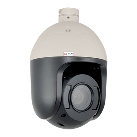
ACTi CAM-6200 User manual

IP Speed Dome
Quick Installation Guide
Ver. 061031
Model: CAM-6200/6220

0-1
0PRECAUTIONS
1. Read these instructions
All the safety and operating instructions should be read before the product is
operated.
2. Heed all warnings
All warnings on the product and in the instruction manual should be adhered to.
The symbol indicates the following items, please carefully read the
description next to each symbol.
a. Failure to follow the safety instruction given may directly endanger
people, cause damage to the system or to other equipment.
b. The requirements to make this device work, including hardware,
computer settings, network settings, and operation procedures.
c. The tips to make using this device easier, more convenient and more
efficient.
3. Servicing
Do not attempt to service this video product yourself as opening or removing
covers may expose you to dangerous voltage or other hazards. Refer all servicing
to qualified service personnel.
Copyright
This manual is the intellectual property of ACTi and is protected by copyright. All
rights are reserved. No part of this document maybe reproduced or transmitted for any
purpose by any means including electronic or mechanical without the official written
permission from ACTi.
Trademarks
All names used in this manual for hardware and software are probably registered
trademarks of respective companies.
Liability
Every care has been taken during writing this manual. Please inform your local office
if you find any inaccuracies or omissions. We cannot be held responsible for any
typographical or technical errors and reserve the right to make changes to the product
0

0-2
and manuals without prior notice.
FCC/CE Regulation
NOTE: This equipment has been tested and found to comply with the limits for a
Class A digital device, pursuant to Part 15 of the FCC Rules. These limits are
designed to provide reasonable protection against harmful interference when the
equipment is operated in a commercial environment. This equipment generates, uses,
and can radiate radio frequency energy and, if not installed and used in accordance
with the instruction manual, may cause harmful interference to radio communications.
Operation of this equipment in a residential area is likely to cause harmful
interference in which case the user will be required to correct the interference at his
own expense.
FCC Caution: To assure continued compliance, (example –use only shielded
interface cables when connecting to computer or peripheral devices). Any changes or
modifications not expressly approved by the party responsible for compliance could
void the user’s authority to operate this equipment.
CE: This device passed the test performed according to the European standard
EN55022:1998 Class A, EN 61000-3-2:2000, EN61000-3-3”1995/A1:2001,
EN55024:1998/A1:2001.

0-3
Table of Contents
0PRECAUTIONS................................................................................................ 0-1
Copyright .....................................................................................................................................0-1
Trademarks ..................................................................................................................................0-1
Liability........................................................................................................................................0-1
FCC/CE Regulation .....................................................................................................................0-2
1Installation ........................................................................................................ 1-1
1.1 Connections .........................................................................................................1-1
1.1.1 Indoor connections ........................................................................................................1-1
1.1.2 Outdoor connections......................................................................................................1-2
1.2 Speed dome setup................................................................................................1-3
1.2.1 Setup camera ID, baud rate and protocol.......................................................................1-3
1.3 Indoor installation...............................................................................................1-5
1.3.1 Punching a hole in the ceiling........................................................................................1-5
1.3.2 Take out the camera.......................................................................................................1-5
1.3.3 Fit the upper casing into the ceiling as shown below. ...................................................1-5
1.3.4 Screw the screws securely to ensure the camera is tightly locked to the ceiling. ..........1-5
1.3.5 Once complete the above steps, place the complete camera (except the dome cover)
back to the ceiling as shown below..............................................................................................1-6
1.4 Outdoor H/W installation procedures...............................................................1-7
1.4.1 Understand Outdoor applications ..................................................................................1-7
1.4.2 Install the mount ............................................................................................................1-9
2Configuration.................................................................................................. 2-10
2.1 Network video platform (Web configurator) setup .......................................2-10
2.1.1 Make sure network environment .................................................................................2-10
2.1.2 Open Internet Explorer with IP address.......................................................................2-11
2.1.3 Login with default administrator’s account & password .............................................2-11
2.1.4 Preview the video ........................................................................................................2-12
2.1.5 Set the new IP address .................................................................................................2-13
2.1.6 Check default video setting .........................................................................................2-14
2.1.7 Click Save Reboot to restore all settings and please wait about 30 seconds for system
reboot. .....................................................................................................................................2-14
0-4
2.2 AP (Streaming Activator) setup.......................................................................2-15
2.2.1 Open Streaming Activator...........................................................................................2-15
2.2.2 Click Setup. .................................................................................................................2-15
2.2.3 Click PTZ setup...........................................................................................................2-16
2.2.4 Click PTZ setup and follow the picture below to setup...............................................2-17
2.2.5 Press the Apply button and reconnect to the IP speed dome. ......................................2-17
2.2.6 PTZ function will work perfectly now.........................................................................2-17
3Appendix.......................................................................................................... 3-18
3.1 Camera ID setup ...............................................................................................3-18

1-1
1Installation
1.1 Connections
Indoor IP speed dome connection is different from the outdoor IP speed
dome. Follow the description below to connect to respective apparatus.
1.1.1 Indoor connections
1. Analog Video-out connector
Connect it to the video-in port of respective apparatus. The signal is 75Ω
Composite Video Signal.
2. DC jack-in for power input
Connect this DC jack to the power supply of 12VDC, 1.0A input.
3. LAN port
The video server connects to the LAN (local area network) via a standard
RJ45 connector. Supporting NWAY, this video server can auto detect the
speed of local network segment (10Base-T/100Base-TX Ethernet).
4. WAN port
The video server connects to the WAN (wide area network) via a standard
RJ45 connector. Supporting NWAY, this video server can auto detect the
1

1-2
speed of local network segment (10Base-T/100Base-TX Ethernet). The
WAN port is for FTTH and connects to an xDSL or cable modem.
1.1.2 Outdoor connections
1. Analog Video-out connector
Connect it to the video-in port of respective apparatus. The signal is 75Ω
Composite Video Signal.
2. Power input
Connect this DC jack to the power supply of 110VAC or 230VAC
according to the product you bought.
3. LAN port
The video server connects to the LAN (local area network) via a standard
RJ45 connector. Supporting NWAY, this video server can auto detect the
speed of local network segment (10Base-T/100Base-TX `Ethernet).
4. WAN port
The video server connects to the WAN (wide area network) via a standard
RJ45 connector. Supporting NWAY, this video server can auto detect the
speed of local network segment (10Base-T/100Base-TX Ethernet). The
WAN port is for FTTH and connects to an xDSL or cable modem.

1-3
1.2 Speed dome setup
Follow the description below setup IP speed dome’s hardware camera ID,
baud rate and protocol.
Speed dome setup Video platform setup
AP (Streaming
Activator) setup
Camera ID, baud rate and protocol setting in these 3 item should be the same
for PTZ control function to work.
1.2.1 Setup camera ID, baud rate and protocol
Loosen the four screws and de-attached the dome cover from the housing.
Follow the tables below to setup each respective parameter.
Address ID Protocol/
Baud Rate
1 2 3 4 5 6 7 8 9 10
Setting of camera ID Address and
Communication Protocol

1-4
zProtocol and baud rate switch
SW9 SW10
PELCO D-2400 OFF OFF
PELCO P-4800 ON OFF
PELCO P-9600
(Recommended)
OFF ON
EYEVIEW ON ON
zCamera ID address setting
Please refer to the Appendix. A “Camera hardware ID setup”

1-5
1.3 Indoor installation
1.3.1 Punching a hole in the ceiling
Remove the target ceiling first, then attach the hole-sticker supplied with
the camera to the ceiling and make the desired hole accordingly with a
proper tool.
1.3.2 Take out the camera
1.3.3 Fit the upper casing into the ceiling as shown below.
1.3.4 Screw the screws securely to ensure the camera is
tightly locked to the ceiling.
Please check carefully, otherwise the camera might fall to cause harm to
itself or other person or properties.

1-6
1.3.5 Once complete the above steps, place the complete
camera (except the dome cover) back to the ceiling as
shown below.

1-7
1.4 Outdoor H/W installation procedures
There are 4 kinds of outdoor application. And each of them requires two
steps to install the outdoor IP speed dome. Please refer to the picture below
to understand each application type.
Then follow the procedure below to install it.
1.4.1 Understand Outdoor applications
zOutdoor Wall mount
Outdoor Housing + outdoor Wall mount
2.4.1.2 Outdoor Ceiling mount
Outdoor Housing + outdoor Ceiling mount

1-8
zOutdoor Corner mount
Outdoor Housing + outdoor Wall mount + outdoor Corner
bracket
zOutdoor Pole mount
Outdoor Housing + outdoor Wall mount + outdoor Pole bracket

1-9
1.4.2 Install the mount
The mounting wall must be strong enough for holding the camera.
Minimum loading capacity should be at least 35 kg or above, for prevention
of fall and personal injury.
Mark the 4 mounting hole centers according to the mount base plate, as
shown below:
200mm
170mm
140mm
114mm
zDrill 4 holes Ø 6.5mm:
zUse the 4 screws provided to fix the mount on the wall

2-10
2Configuration
2.1 Network video platform (Web
configurator) setup
2.1.1 Make sure network environment
Default IP of IP Speed Dome is 192.168.0.100. Please make sure IP Speed
Dome and your PC is on the same network segment before running the
installation.
2
Please set the settings as
below.
IP address: 192.168. 0.xxx
Subnet mask: 255.255.255.0
(NOTE: xxx should be a number
from 1 to 254, but 100 is
excepted.)

2-11
2.1.2 Open Internet Explorer with IP address
NOTE: If your web browser is earlier than IE6, then download IE6 is
recommended.
NOTE: The IP high speed dome default IP address is set to
192.168.0.100
2.1.3 Login with default administrator’s account &
password
NOTE: Default administrator account is set to Admin, password is set to
123456, and click button.

2-12
2.1.4 Preview the video
NOTE: In your Client PC, please make sure the setting of Network
Connections Type is set to Auto Negotation, since IP high speed dome
follows MII standard. Otherwise, you might not see the live image.

2-13
2.1.5 Set the new IP address
zHost Name : Enter in the domain name, Default Host Name is ACTi.
zLanguage : Language setting for Web Configurator after Save Reboot.
Default setting is English.
zIP Address : The IP address of the LAN interface. The default IP
address is 192.168.0.100.
zSubnet Mask : The subnet mask of the LAN interface.The default
subnet mask is 255.255.255.0
zClick button
NOTE: Check with your MIS department, if Client PC and IP high speed
dome are setting in different VLANs, please connect to WAN port.
NOTE: In your Client PC, please make sure the setting of Network
Connections Type is set to Auto Negotation, since IP high speed dome
follows MII standard. Otherwise, you might not see the live image.
IMPORTANT: After the IP address is changed, please record this IP
address. There is no way to connect to the IP high speed dome if user
forgets the new IP address.

2-14
2.1.6 Check default video setting
The streaming type [Version 1.0] – without audio function
The streaming type [Version 2.0] – with audio function
NOTE: Please make sure the TV Input (NTSC / PAL) is meet your
requirement, and click button.
2.1.7 Click Save Reboot to restore all settings and please
wait about 30 seconds for system reboot.

2-15
2.2 AP (Streaming Activator) setup
Please follow the procedures below to setup the PTZ function of the
Streaming Activator. Wrong settings will cause CAM-62xx SERIES PTZ
function doesn’t work.
2.2.1 Open Streaming Activator.
2.2.2 Click Setup.
This is an example setting in 1.36.02. version, other software
version please refer to this setting as well.
Other manuals for CAM-6200
1
This manual suits for next models
1
Table of contents
Other ACTi Security Camera manuals