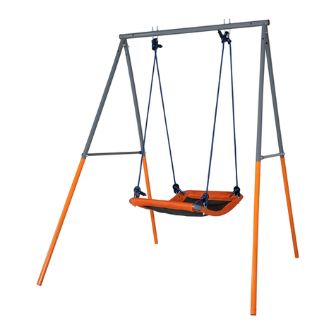
Action Sports Equipment S000665 Maintenance manual

Action Sports Equipment Pty Ltd.
72 Silverwater Rd, Silverwater, NSW, Australia, 2128
Parts & Service Enquiries: 1800 465 070 (Australia); 09 477 6020 (New Zealand)
Sales Enquiries: 1800 777 137 (Australia); 09 477 6020 (New Zealand)
Or visit our website: www.actionsports.com.au
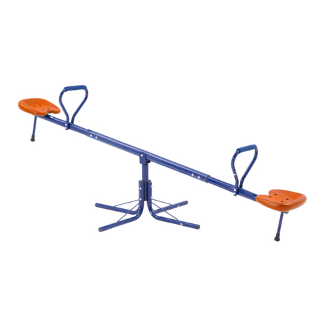
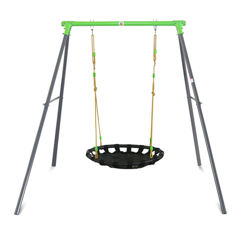
4-Unit Swing Set with Seesaw & Bonus Swing Seat
Model: S000665
Assembly, Installation, Care, Maintenance and Use Instructions
Plus Bonus swing seat piece.
This can be substituted for the tot swing.
IMPORTANT
Please read and retain this manual as it will assist with identification for parts and service.
Read these materials prior to assembling and using this swing set.
This Product is for Domestic Use Only.
- Warning -
- This swing set is for family domestic use only.
- This swing set is designed for use by children 3-9 years of age weighing no more than 34kgs.
- This swing set has a maximum weight limit of 238kgs.
- Children of all ages must be supervised by an adult at all times when using this swing set.
- Adult assembly of this swing set is required. Two adults are recommended for assembly.
© ACTION SPORTS EQUIPMENT PTY LTD – www.actionsports.com.au Page:1

- WARNING -
1) Read and understand enclosed safety information before assembly and use of the swing set.
2) Place the swing set on a level and soft surface before use.
3) Lateral clearance is essential. The swing set should be placed not less than 2m (6 feet 6 inches) from any
structure or obstruction ie. a fence, garage, house, shed, overhead branches, clothes line etc.
4) DO NOT install this swing over hard surfaces such as concrete, asphalt or any other hard surface.
5) It is recommended that this swing set be positioned over soft lawn or fine sand.
6) Anchor the swing set using the wiggling anchor pegs provided to prevent overturning or lifting. The anchors
should be placed level with or under the ground in order to reduce the tripping hazards.
7) Never place the swing set under or near powerlines.
8) Never place the swing set inside a garage or basement or under any structure.
9) Always position the swing where it can be seen from the house.
10) This swing set is designed to be used by one child per seat at one time.
11) Do not allow additional items to be attached to the swing set such as ropes, chains, cords, or other items not
designed for use.
12) Do not use the swing set when it is wet as it will become slippery and serious injury may result.
13) Do not wear apparel such as hats with chin straps, helmets, scarves, garments with pull strings and other items
of loose clothing while using this swing set as they can cause serious injury.
14) Do not walk close to, in front of or behind the swing set when in use. Walking between moving rides can
cause serious injury.
15) Do not jump from the swing set when they are in motion.
16) Do not stand on the seats when using the swing set.
17) Do not climb on the side braces or the top support of the swing set.
© ACTION SPORTS EQUIPMENT PTY LTD – www.actionsports.com.au Page:2

TABLE OF CONTENTS
TABLE OF CONTENTS.................................................................................................................3
PARTS LIST – MAIN FRAME.......................................................................................................4
PARTS LIST – SWING SEAT.........................................................................................................5
PARTS LIST – TRAPEZE...............................................................................................................5
PARTS LIST – TOT SWING...........................................................................................................5
PARTS LIST – GLIDE RIDER .......................................................................................................6
PARTS LIST – SEESAW.................................................................................................................7
PARTS MATCH LISTS – 1:1 Actual Scale.....................................................................................8
ASSEMBLYAND INSTALLATION INSTRUCTION ................................................................13
SECTION 1- MAIN FRAME ASSEMBLY..................................................................................14
SECTION 2 – SEESAW................................................................................................................16
SECTION 3- SWING SEATASSEMBLY....................................................................................19
SECTION 4 – TRAPEZE ASSEMBLY ........................................................................................20
SECTION 5 – GLIDE RIDER ASSEMBLY.................................................................................22
SECTION 6 – ANCHOR PEGS....................................................................................................23
MAINTENANCE INSTRUCTION...............................................................................................24
CAUTION......................................................................................................................................24
LIMITED WARRANTY………………………………………………………………………...25
© ACTION SPORTS EQUIPMENT PTY LTD – www.actionsports.com.au Page:3

PARTS LIST – MAIN FRAME
Parts # Parts Description Quantity
MF-1a Top Support Tube A
1
MF-1b
Top Support Tube B 1
MF-1c
Top Support Tube C 1
MF-2
Top Support Tube Brace 2
MF-3
Leg Stay 2
MF-4
Upper Leg Tube 4
MF-5 Lower Leg Tube with Foam 3
MF-6 Right Lower Front Leg Tube
(with a hole at the middle of
tube)
1
MF-6a Leg Foam (pre-assembled to
MF-6) 1
MF-7
Anchor Peg 5
MF-8 Foam Sleeve A 3
MF-9 Foam Sleeve B 1
© ACTION SPORTS EQUIPMENT PTY LTD – www.actionsports.com.au Page:4

PARTS LIST – SWING SEAT
Parts # Parts Description Quantity
MS-1
Swing SeatAssembly 2
MS-2
Eyebolt Assembly
(built- in to MS-1) 4
X6
Oval Opening Cap
(built-in to MS-2) 4
X16
Plastic Lock (built-in to
MS-2) 4
PARTS LIST – TRAPEZE
Parts # Parts Description Quantity
TZ-1
Trapeze Assembly 1
TZ-2
Eyebolt & Link
Assembly (built-in to
TZ-1)
2
TZ-3
Oval Opening Cap
(built-in to TZ-2) 2
TZ-4
Plastic Lock (built-in
to TZ-2) 2
PARTS LIST – TOT SWING
Parts # Parts Description Quantity
TS-1 Tot Swing Upper
Hanger Tube
2
TS-2
Tot Swing Lower
Handle Tube 2
© ACTION SPORTS EQUIPMENT PTY LTD – www.actionsports.com.au Page:5

TS-3
Tot Swing Armrest
Tube with foam and
cover
1
TS-4 Tot Swing Support
Tube with foam and
cover
1
TS-5 Seat and Back Plate
(seat plate with one
hole at the centre of
front panel)
2
TS-6
Eyebolt Assembly
(built-in to TS-1) 2
PARTS LIST – GLIDE RIDER
Parts # Parts Description Quantity
GR-1
Glide Rider Upper
Hanger Tube 2
GR-2 Glide Rider Lower
Hanger Tube 2
GR-3 Glide Rider Seat Tube 2
GR-4
Glide Rider Seat 2
GR-5 Glide Rider Foot Step 2
X3 Bracket 4
X6 Plastic Bearing 2
U3 T-Shaped Washer 4
© ACTION SPORTS EQUIPMENT PTY LTD – www.actionsports.com.au Page:6

PARTS LIST – SEESAW
Parts # Parts Description Quantity
SS-01
Connector 1
SS-02 Curved Leg Tube 1
SS-03 Centre Beam 1
SS-04
Seat Beam 2
SS-05
Handle 2
SS-06
Seat 2
SS-07
Arc Bolt 1
SS-08 Hex Nut 1
SS-09
Plastic Cap A (built-in
to SS03) 2
SS-10
Plastic Cap B (built-in
to SS03) 1
© ACTION SPORTS EQUIPMENT PTY LTD – www.actionsports.com.au Page:7

PARTS MATCH LISTS – 1:1 Actual Scale
© ACTION SPORTS EQUIPMENT PTY LTD – www.actionsports.com.au Page:8

© ACTION SPORTS EQUIPMENT PTY LTD – www.actionsports.com.au Page:9

© ACTION SPORTS EQUIPMENT PTY LTD – www.actionsports.com.au Page:10

© ACTION SPORTS EQUIPMENT PTY LTD – www.actionsports.com.au Page:11

© ACTION SPORTS EQUIPMENT PTY LTD – www.actionsports.com.au Page:12

Tools included in the Item
Wrench Allen Key
A socket set and adjustable spanner may also be used to further assist in swing assembly.
- IMPORTANT -
Use this parts list to make sure all parts are present before assembly. Do not attempt to
assemble the swing set if any parts are missing or damaged. Disassemble the Swing Set
immediately if any part is missing or any unsafe condition exists. Obtain a replacement
part to properly correct the hazard by calling 1800 465 070 (Australia) or 09 477 6020
(New Zealand). Do not allow use of the swing set until the hazard has been corrected.
ASSEMBLYAND INSTALLATION INSTRUCTION
Read this entire assembly section before beginning to assemble your swing set. Carefully follow each
step.
NOTE:At least 2 persons are recommended for the following assembly.
In order to avoid injuries and damage to property, it
is recommended that the Swing Set should be at
least 2 metres away from any buildings, fences and
so on. Also clear the ground of any sharp objects.
Use the Parts List to make sure all parts are present. Contact Customer Service at 1800 465 070
(Australia) or 09 477 6020 (New Zealand) if any parts are missing. Do not attempt to assemble the
swing set if any parts are missing.
© ACTION SPORTS EQUIPMENT PTY LTD – www.actionsports.com.au Page:13

SECTION 1- MAIN FRAME ASSEMBLY
Note: At least two people are required for the assembly of the swing set.
Caution: The swing set should be placed on a soft surface, such as a grassed lawn area is
recommended.
1.1 Lay out the top frame on a soft and level surface as Fig. 1.Align holes, connect the Top Support Tubes
(MF-1a,b,c) and the Top Support Tube Braces (MF-2), using Bolts, Washers & Nuts of A2 &A3. See Fig.2
Figure 1
Figure 2
1.2 Slide the Lower Leg Tubes (MF-5 & MF-6) into the Upper Leg Tubes (MF-4), align holes. Make sure the
Lower Leg Tube (MF-6) is placed at the right front side. Attach the connector (SS-01) to the right front leg
tube (MF-6). See Fig.3
Figure 3
© ACTION SPORTS EQUIPMENT PTY LTD – www.actionsports.com.au Page:14

1.3 Slide the Foam Sleeve (MF-8) to the Lower Leg Tubes (MF-5) to cover the leg foam. Fix the connector
(SS01) with Bolt, Washer & Nut of S1. Please see Figure 4.
Figure 4
1.3 Secure the completed Leg Tubes to the Top Support Tube Braces (MF-2) with Bolts, Washers & Nuts of A3.
Put the Leg Stay (MF-3) onto the leg tube. Align holes and fasten with Bolts, Washers & Nuts of A1.
Attach the leg foam (MF-6a) and Sleeve (MF-9) to cover the right front leg (MF-6). When it is completed,
the swing set main frame will look like as Figure 5.
Figure 5
© ACTION SPORTS EQUIPMENT PTY LTD – www.actionsports.com.au Page:15

SECTION 2 – SEESAW
2.1 Insert the Plastic Caps (SS-09 & SS-10) to the Centre Beam (SS-03) as figure 6.
(The plastic caps are supposed pre-installed in the package. Do the assembly in case they are loosened.)
Figure 6
2.2 Slide the Centre Beam (SS-03) to the Curved Leg Tube (SS-02) as figure 7. Secure with Arc bolt (SS-07)
and Hex Nut (SS-08). See figure 8.
Figure 7
Figure 8
© ACTION SPORTS EQUIPMENT PTY LTD – www.actionsports.com.au Page:16

2.3 Attach the Curved leg tube (SS-02) to the Connector (SS-01) and fix with Bolt, Washer & Nut (S2).
See figure 9.
Figure 9
2.4 Connect the Seat Beams (SS-04) to the Centre Beam (SS-03). Fasten with Bolts, Washers & Nuts (S4) as
figure 10.
Figure 10
© ACTION SPORTS EQUIPMENT PTY LTD – www.actionsports.com.au Page:17

2.5 Attach the Handles (SS-05) to the Seat Beams (SS-04) and fix with Bolts, Washers & Nuts (S3).
Place the Seats (SS-06) onto each of the Seat Beams (SS-04). Secure with Bolts, Washers & Nuts (S5).
See Figure 11.
When it is completed, the seesaw will look like as Figure 12.
Figure 11
Figure 12
© ACTION SPORTS EQUIPMENT PTY LTD – www.actionsports.com.au Page:18

SECTION 3- SWING SEATASSEMBLY
Attach the Swing Seat to the Main Frame as shown Figure 13.
Figure 13
WARNING!
DO NOT OVER TIGHTEN EYEBOLTS!
THIS CAN RESULT INASSEMBLY FAILURE!
© ACTION SPORTS EQUIPMENT PTY LTD – www.actionsports.com.au Page:19

SECTION 4 – TRAPEZEASSEMBLY
Attach the Trapeze to the Main Frame as shown Figure 14.
Figure 14
WARNING!
DO NOT OVER TIGHTEN EYEBOLTS!
THIS CAN RESULT INASSEMBLY FAILURE!
© ACTION SPORTS EQUIPMENT PTY LTD – www.actionsports.com.au Page:20
Table of contents
Other Action Sports Equipment Swing Set manuals
Popular Swing Set manuals by other brands

Ledon
Ledon 1170 Assembly instructions
BOERPLAY
BOERPLAY Swing Galileo V manual
Rompa
Rompa TheraGym Over the Moon Swing Set A 21581 manual
Terra Bound Solutions
Terra Bound Solutions 581-504 Assembly instructions

GALOPIN
GALOPIN L16 instruction manual
Lemeks
Lemeks Palmako HENRY MV100-4420 Assembly, installation and maintenance instructions
