Active Cool AC4G User manual

AC4G
User’s Manual
The world’s first thermoelectric cooler for PC processors
www.activecool.com

Entire contents of this manual © 2003 Active Cool Ltd. Ashkelon, Israel.
Reproduction in whole or in part without permission is prohibited.
Active Cool is a registered trademark of Active Cool Ltd.
AC4G is a trademark of Active Cool Ltd.
All other names are trademarks of their respective owners.
Active Cool Service Department
e-mail: [email protected]
phone: +972 (8) 672 6123
fax: +972 (8) 672 6124
visit us: www.activecool.com
Compliance
This equipment has been tested and found to comply with the Class B digital
device, under FCC, CE, and VCCI rules. These rules are designed to ensure
reasonable protection against harmful interference in a residential installation.
Modifications made to this device not expressly approved by Active Cool Ltd. could
void the user’s authority to operate the equipment.
Safety warning
Active Cool AC4G has no user-serviceable parts and contains
potentially hazardous voltages. To prevent risk of electric shock,
do not open the unit under any circumstances. Do not attempt to
power the AC4G from any source other than a grounded electric
outlet protected by a fuse or circuit breaker.
Not for use in life-support systems.
2 Active Cool AC4G User's Manual

Package Contents
1. User’s Manual & Quick Start
2. AC4G PCI card
3. AC4G Cooling Unit (for either AMD or Intel)
4. 2 heat sink clips (Intel cooling unit only)
5. Power cord
6. Silicone compound (small sachet)
Figure 1. Package contents
Installation
Preparation
1. Shut down the computer, and disconnect it from the mains electricity
supply.
2. Leave the computer to cool down, and then remove the existing CPU
k.heat sin
Warning: If the computer has been in use the CPU area may be
very hot. Do not touch any parts until you are sure they have cooled
down.
Cooling unit installation
Figure 2 shows the AC4G Cooling Unit for AMD64. Figure 3 shows the
AMD unit heat sink clip.
Active Cool AC4G User's Manual 3

Figure 2. Figure 2. Cooling unit for AMD64
Heat Sink
Cold Plate
Heat Sink
metal cli
p
CPU Fan
Large connector
(Input/Output)
Small connector
(Motherboard)
3 Apply a thin layer of silicone compound (from the small sachet) to
the bottom of the cold plate.
4. Position the AC4G cooling unit on the CPU so that the cold plate sits
squarely over the CPU.
Figure 3. AMD unit heat sink clip: being secured (A); secured (B)
5. Use the heat sink clip (AMD) or clips (Intel) to clamp the cooling unit
securely to the retention mechanism on the motherboard.
PCI card installation
1. Place the AC4G PCI card in any free PCI slot.
4 Active Cool AC4G User's Manual

Figure 3. PCI card inserted into a PCI slot
2. Connect the small connector to the CPU fan connector on the
motherboard.
3. Connect the large connector to the input/output connector on the
back of the AC4G PCI card (see Figure 7).
Figure 4. AC4G PCI card – rear view
4. Disconnect the front and rear case fans from the PC power supply.
Connect the front and rear fans to each other, and then connect
them to the front/rear case fan connector on the back of the AC4G
PCI card.
5. Verify that the CPU fan and all case fans are unobstructed.
6. Connect the supplied power cable to the power plug on the bracket of
the AC4G PCI card, and connect the other end to the electric mains
(100–240V).
Active Cool AC4G User's Manual 5

Figure 5. AC4G PCI card – bracket-side
7. Connect the PC to the electric mains.
8. Power up the PC.
9. Verify that the all three LEDs on the AC4G PCI card are lit.
10. Put the PC cover back on.
Installation is complete.
Operation
In order for any cooling system to work efficiently there must be free air
flow around the PC case. The PC should not be enclosed in a cabinet, and
there should be at least 10cm between the back of the PC and the wall or
furniture.
1. Connect the PC to the electric mains.
2. Connect the power plug on the bracket of the AC4G PCI card to the
electric mains (100–240V).
Note: Once AC4G is installed, the computer itself will not operate unless the
AC4G is connected to the electrical mains.
3. Power up the PC.
As the PC powers up, the blue PCI card LED (at the back of the
computer) blinks five times, and then remains alight, indicating that
AC4G is functioning properly.
6 Active Cool AC4G User's Manual

Cooling modes
The AC4G gives you cooling and noise reduction in a single system. It
can be run in either of two modes: Extra-quiet mode (default) or
Extra-cool mode (see Figure 7, page 8).
In Extra-quiet mode, as the graph illustrates, AC4G control allows a
small temperature increase (∆T) before turning the fans on. This
minimizes fan noise, while maintaining a significant cooling advantage
over conventional coolers.
In Extra-cool mode, cooling begins whenever CPU temperature begins
to rise. The result is an extra-cool CPU, with mildly increased fan noise.
Figure 6. AC4G Cooling Modes
Switching between modes
The cooling mode for the system is determined by a removable jumper in
the power and control unit (see Figure 7,page 8). To switch between
modes either remove or replace the jumper.
•Jumper inserted (default) - the system is in Extra-quiet mode.
•Jumper removed - the system is in Extra-cool mode.
Active Cool AC4G User's Manual 7

Warning: Disconnect the computer and the AC4G unit from the power
source before removing or inserting the jumper.
Figure 7. Location of the removable circuit jumper on PCI card
Troubleshooting
The blue LED on the bracket-side of the AC4G PCI card, next to the AC
power connector (see Figure 5 page 6) indicates that the AC4G system
is functioning properly. During normal operation the blue LED is on
continuously. During power up from quiet mode to high-power cooling
the LED blinks five times.
Reading AC4G LEDs
In addition to the blue LED that is visible at the back of the PC (see
Figure 5, page 6), two green LEDs are located to the rear of the PCI card
(see Figure 4, page 5) and are visible only when the cover is removed.
Together these three LEDs indicate AC4C status, and can help in
troubleshooting.
8 Active Cool AC4G User's Manual

Table 1: LED status summary
LED State Meaning
Blue ON continuously Normal operation. All systems OK.
Blinks 5 times Transition from quiet mode to high-power
cooling.
OFF No AC current.
Constant
blinking
CPU fan stalled.
(If the CPU fan stalls blinking of the LEDs is
preceded by a screen warning.)
Green (inner) ON Receiving 5V through PCI connector.
OFF Not receiving 5V through PCI connector.
Green (outer) ON Receiving 12V through PCI connector.
OFF Not receiving 12V through PCI connector.
Blinking Short or overload in one of the fans.
Troubleshooting suggestions
Table 2: Troubleshooting suggestions
Problem LED status Possible cause Action
PC does not
power up or
resets
continuously.
Blue LED
permanently
OFF.
No power to
AC4G PCI card.
Check power cord from AC4G
PCI card bracket to electrical
mains.
No power to PC Check power cord from
computer to mains.
Screen alert
appears, then
screen blanks
out.
Blue LED
blinking.
CPU fan stalled. Make sure CPU fan is working
properly (it may be jammed
by a physical obstruction or
disconnected from the power
source).
Active Monitor
on computer
screen
indicates that
CPU fan is not
working.
Connector from
Cooling Unit to
motherboard
not properly
connected.
Make sure connector from
Cooling Unit to motherboard
is connected properly to the
CPU fan connector on the
motherboard.
Active Cool AC4G User's Manual 9

10 Active Cool AC4G User's Manual
Problem LED status Possible cause Action
Blue and
Green LEDs
blinking.
Overload from
case fans.
In the unlikely event of the
case fans drawing more
than 1 Amp, disconnect one
or more case fans from the
installation (and run them
directly from their
designated power supply).
One or both
green LEDs
not lit.
PCI card not
connected
properly to PCI
slot.
Remove AC4G PCI card and
set it in the PCI slot again.
Table of contents
Other Active Cool Computer Hardware manuals
Popular Computer Hardware manuals by other brands
ST
ST X-NUCLEO-AMICAM1 user manual

Ultra Products
Ultra Products X-Wind High Performance CPU Cooler ULT33048 Specification sheet
Sony Ericsson
Sony Ericsson GM-41 Phase II Integrator's manual
IOGear
IOGear GWP512 quick start guide

HPE
HPE StoreEver 1/8 G2 Getting started guide
Alphacool
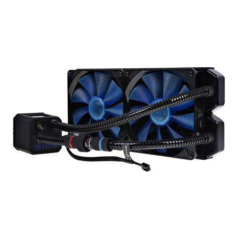
Alphacool Eisbaer 280 manual

