QUICK START GUIDE
HARRIER USB/HDMI CAMERA INTERFACE BOARD
Version 1.7 – March 2021
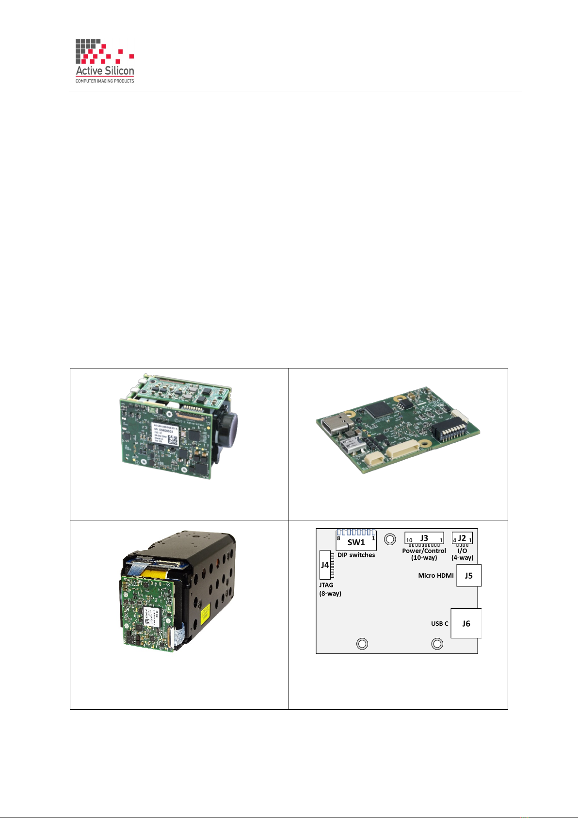
5. Set/check the DIP switch settings, e.g. SW1 [1-4] OFF (no mode change on power up),
SW1 [5-8] OFF (RS232 serial communications mode), or SW1 [7] ON for UVC/USB control.
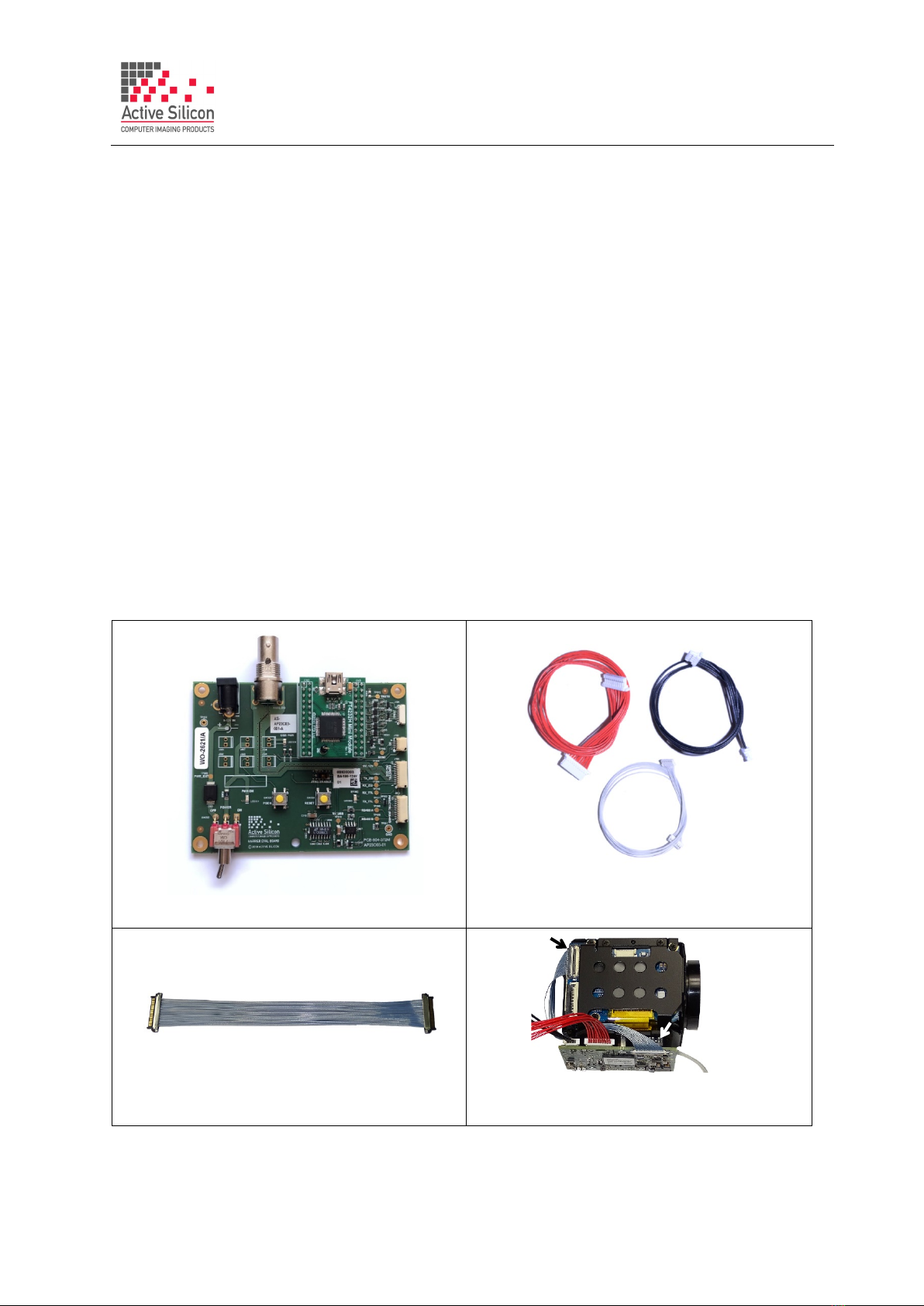
6. Set the Harrier Evaluation Board power switch (SW302) to OFF (left, viewed from above).
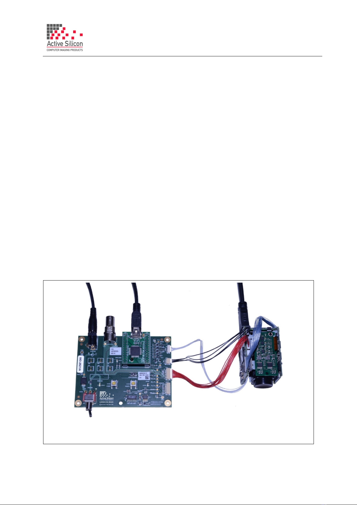
7. Connect the power supply barrel connector to the Harrier Evaluation Board power input
connector (J306) and plug in the power supply using the plug adapter suitable for your region.
8. HDMI: to see the camera output on HDMI, connect the camera interface board micro HDMI out
connector (J5) to a monitor that can display the video modes that you intend to use (maximum
1080p60) using the micro HDMI cable. Note: some monitors are not able to display 1080p30.
9. Unless you want to power the board from the USB cable, switch ON the Harrier Evaluation
Board power switch (SW302). The PWR ON LED should light up.
10. USB/UVC: to see the camera output on USB/UVC, connect the camera interface board USB
Type C connector (J6) to a PC USB Superspeed capable socket using the 5 Gbps USB Type C
cable. Note the board will try to power up from the USB cable unless power from the Harrier
Evaluation Board is being used.
11. The camera will make audible mechanical noises as it goes through its power up sequence and
after a short time the video outputs will be working.
Note: if the DIP switches have been used to set the camera mode, and the mode last used was
different to the DIP switch setting, it will take a few seconds for the camera interface board to
detect this, change the camera mode and re-start the camera.
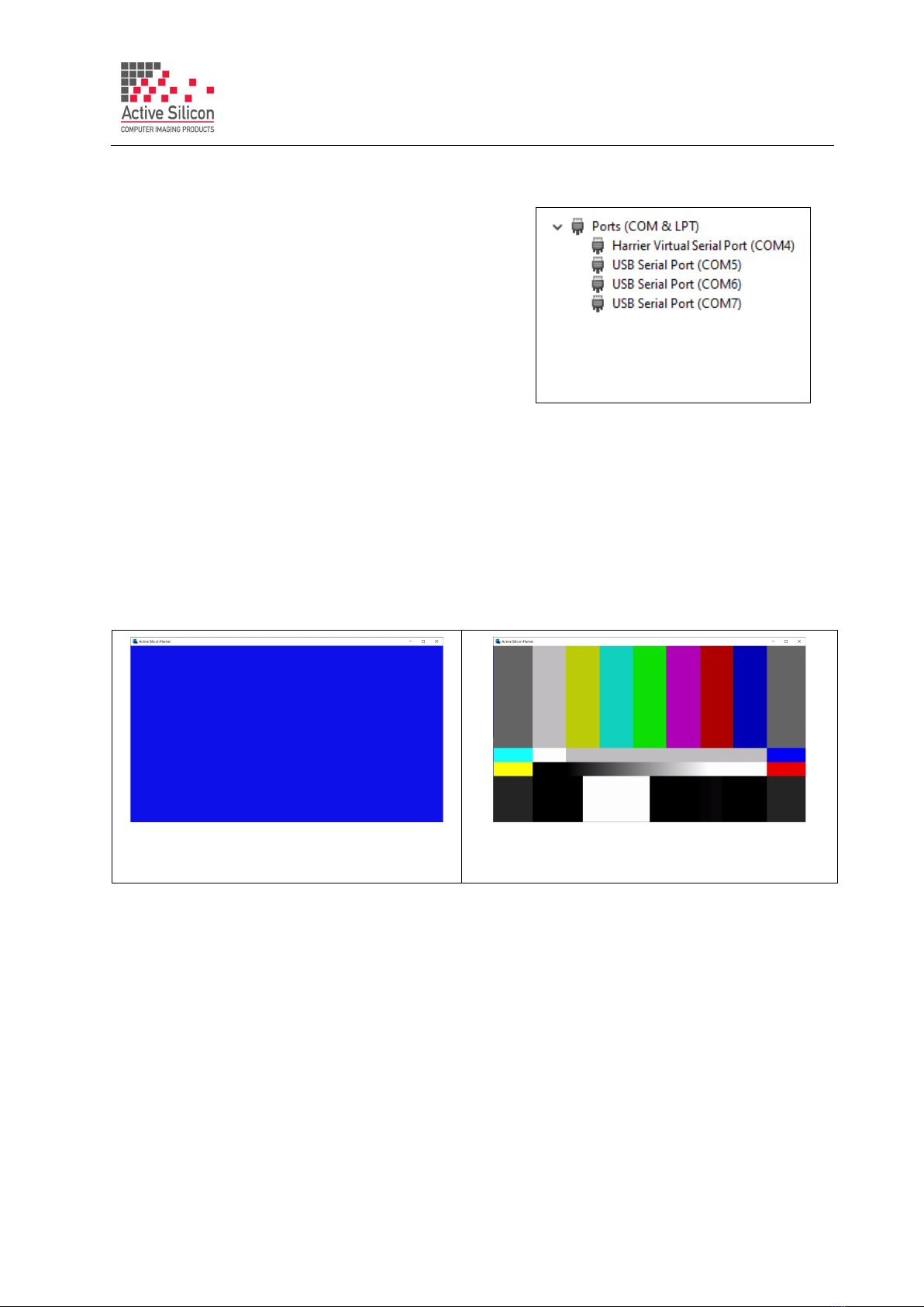
12. Please check that the camera identifies correctly in Windows Device Manager, e.g. Active Silicon
Harrier 10LHD-2 or Active Silicon Harrier T2030-2 etc. For a list of supported cameras please
see the section the end of this document.To re-configure your board please see the section
Configuring the Board for the Camera.
13. HDMI: If the HDMI cable is connected you will see the camera video on the monitor
(if the monitor supports the mode set on the camera).
14. USB/UVC: If the USB Type C cable is connected you can start your UVC application and it will
capture the camera video (video mode settings for the camera and UVC application must
match). If you do not have a UVC application, download and install Harrier USB SDK from the
Active Silicon website. This SDK contains the HarrierView UVC example application. For
instructions on how to use HarrierView please see the section Using the Harrier USB SDK
Example Application below).
15. RS-232/RS-485/TTL control:The Tamron Camera Control Application provides an easy way to
use serial communications; please see the section Using the Tamron Camera Control
Application below. This application can be used with other cameras, but the controls may not
be compatible. The HarrierControl command line software can be used instead, this can be
downloaded from the Software/ HarrierControl section of www.ActiveSilicon.com.
To use your own program you can use the three COM ports that are set up when the Harrier
Evaluation board is plugged in. Typically, the lowest COM port number is the RS-232 interface,
the middle port number is the RS-485 interface and the highest port number is the TTL interface.
COM port settings for Harrier interface boards are (baud rate is user selectable):