2CP05 - CP10 Control Interface Insert
Doc. No.0525-035 Ver. 6 220307
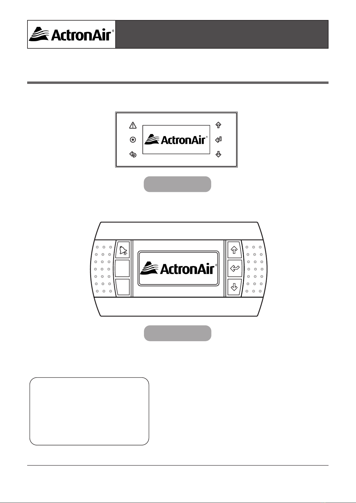
CP05 & CP10 CONTROL INTERFACE INSTALLATION GUIDE
INTRODUCTION
This guide covers the installation and application of ActronAir CP05 and CP10 control interfaces. Functions,
graphic displays and operations of both control interfaces are identical, therefore the two interfaces can be
interchangeable parts and can also be combined as a dual control with mimic logic. Except for the character
height, some dierence in button symbols, and the physical size, shape and colour of the casings, both control
interfaces provide the control exibilty required for your air conditioning system's optimum operation. Note that
there is also a minor dierence in addressing the Mimic display procedures, which is explained in the aected
steps below.
The CP05 and CP10 graphic display are electronic devices which are compatible with ActronAir commercial
control systems. The control interfaces allow complete management of graphics by the display of icons,
management of international fonts and acoustic signal through piezoelectric buzzer. The display icons are
dened at the application software development level while the fonts are in two sizes of 6x8 and 12x16 pixels.
The application software resides on the outdoor controller, therefore the control interfaces does not require any
additional software for operation.
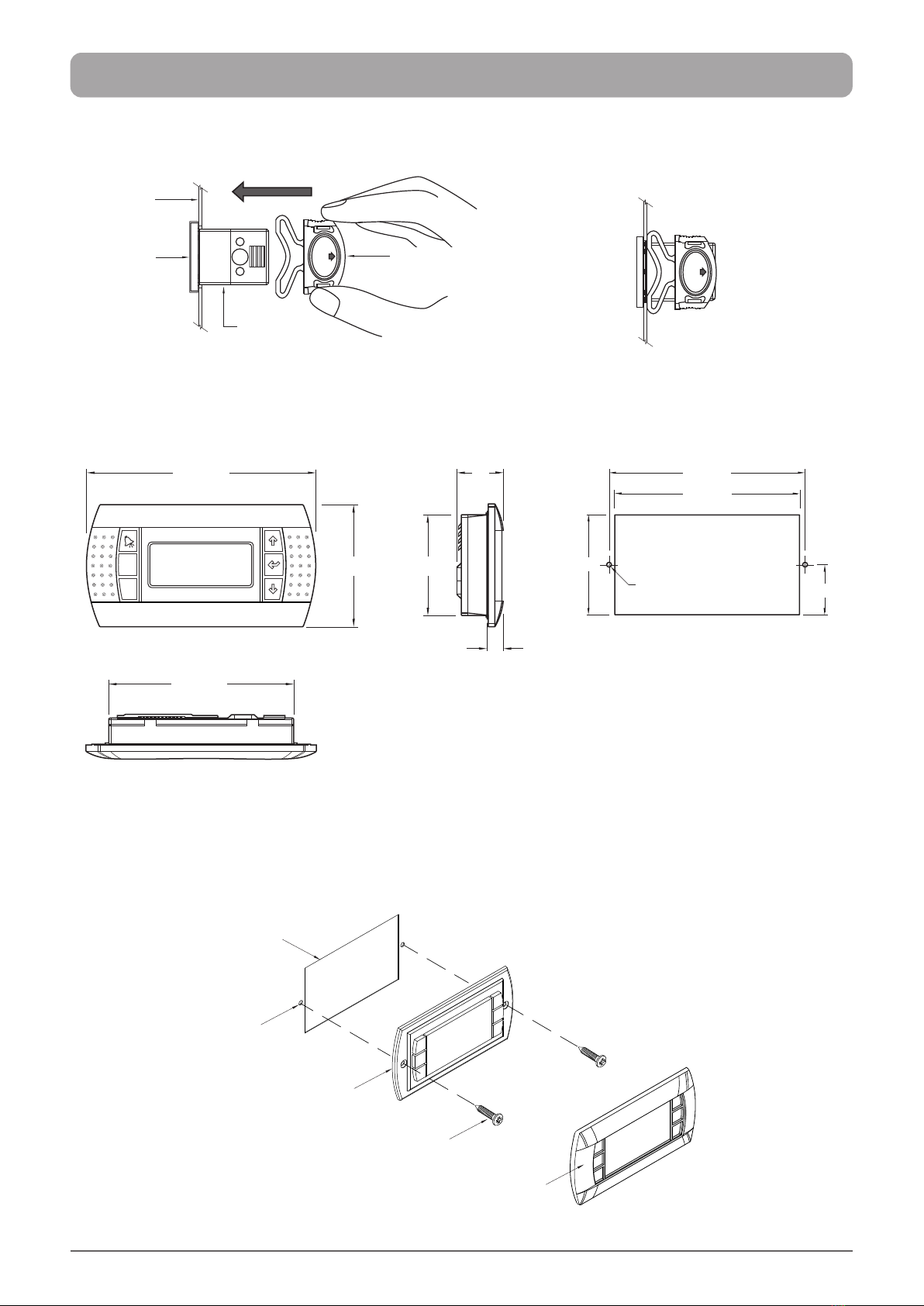
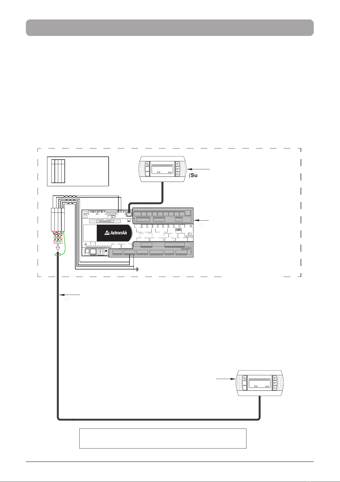
The standard control set up for the Hercules and Large Commercial units provides a single display monitor. This
is either a CP05 or CP10 Control Interface which is mounted on the unit's electrical panel. There are situations
where monitoring is required away from the unit, such as in a control room or in bulding management oce.
The ideal solution to such requirement is to provide a secondary control interface, which acts as a dual control
interface. The secondary control interface will be wired to the system and can be mounted away from the unit.
The dual control interfaces mimic each other, however the control interface most recently accessed has the
priority over the other. For your dual control interface, you may have an option to use two CP05, two CP10 or one
CP05 and one CP10, depending on your situation and requirement.
The following procedures will dicuss the installation, conguration, specications, components required and
addressing the Mimic display of your dual control interface.
1.1. Read all instructions in this manual before operating the air conditioning unit. Failure to do so may result inRead all instructions in this manual before operating the air conditioning unit. Failure to do so may result in
damage to the unit and void your warranty.damage to the unit and void your warranty.
2. 2. Turn-O power from mains supply by removing fuse or switching the circuit breaker to the "O" position Turn-O power from mains supply by removing fuse or switching the circuit breaker to the "O" position
before installation or servicing this control interface.before installation or servicing this control interface.
3.3. Follow sound Lock Out & Tag Out procedures to ensure that power supply is not re-energised accidentally.Follow sound Lock Out & Tag Out procedures to ensure that power supply is not re-energised accidentally.
4.4. This control interface has power supply from the control board via telephone connector, with voltage ofThis control interface has power supply from the control board via telephone connector, with voltage of
18-30VDC Class II & maximum power input of 0.5W. Ensure that this unit is not installed on voltages higher 18-30VDC Class II & maximum power input of 0.5W. Ensure that this unit is not installed on voltages higher
than 30V DC supply.than 30V DC supply.
5.5. Ensure that the unit installation complies with relevant council regulations and building code standards.Ensure that the unit installation complies with relevant council regulations and building code standards.
All electrical wiring must be in accordance with current electrical authority regulations and all wiringAll electrical wiring must be in accordance with current electrical authority regulations and all wiring
connections to be as per electrical diagram provided.connections to be as per electrical diagram provided.
6. WH&S rules and regulations must be observed and will take precedence during installation process.
7. Only use this Control Interface with an ActronAir air conditioner as described in this installation guide.
SAFETY PRECAUTIONS
1.1. Please read this guide thoroughly and understand the procedure before performing the installation andPlease read this guide thoroughly and understand the procedure before performing the installation and
conguration of your Control Interface.conguration of your Control Interface.
2. 2. OnlyOnly qualied techniciansqualied technicians**are allowed to perform these procedures.are allowed to perform these procedures. The customer, both end user, specier
and installer, assume all liability and risks relating to the conguration of the product in order to reach the
expected results in relation to the specic design and system installation. Actron Air, based on specic
agreements, may be consulted for the positive commissioning, installation and application of the unit, however
in no case does it accept liability for the correct operation of the nal equipment / system.
IMPORTANT NOTES
**Qualications required will be appropriate Electrical, Refrigeration and Refrigerant Handling License & Training, dependent on local State/Territory regulations.