IFM CR3130 Application guide

Device manual
CANwireless
CAN Wi-Fi /Bluetooth interface
CR3130
CR3131
7391106 / 00 12 / 2016
UK

Installation instructions CANwireless CR3130/CR3131
2
Contents
1 Preliminary note � � � � � � � � � � � � � � � � � � � � � � � � � � � � � � � � � � � � � � � � � � � � � � � � � 4
1�1 Symbols used� � � � � � � � � � � � � � � � � � � � � � � � � � � � � � � � � � � � � � � � � � � � � � � 4
1�2 Warnings used � � � � � � � � � � � � � � � � � � � � � � � � � � � � � � � � � � � � � � � � � � � � � � 4
2 Safety instructions � � � � � � � � � � � � � � � � � � � � � � � � � � � � � � � � � � � � � � � � � � � � � � � 5
2�1 General� � � � � � � � � � � � � � � � � � � � � � � � � � � � � � � � � � � � � � � � � � � � � � � � � � � � 5
2�2 Target group � � � � � � � � � � � � � � � � � � � � � � � � � � � � � � � � � � � � � � � � � � � � � � � � 5
2�3 Electrical connection � � � � � � � � � � � � � � � � � � � � � � � � � � � � � � � � � � � � � � � � � 5
2�4 Air traffic � � � � � � � � � � � � � � � � � � � � � � � � � � � � � � � � � � � � � � � � � � � � � � � � � � � 5
2�5 Explosive substances� � � � � � � � � � � � � � � � � � � � � � � � � � � � � � � � � � � � � � � � � 5
2�6 Electronic devices � � � � � � � � � � � � � � � � � � � � � � � � � � � � � � � � � � � � � � � � � � � 5
2�7 FCC (USA) � � � � � � � � � � � � � � � � � � � � � � � � � � � � � � � � � � � � � � � � � � � � � � � � � 6
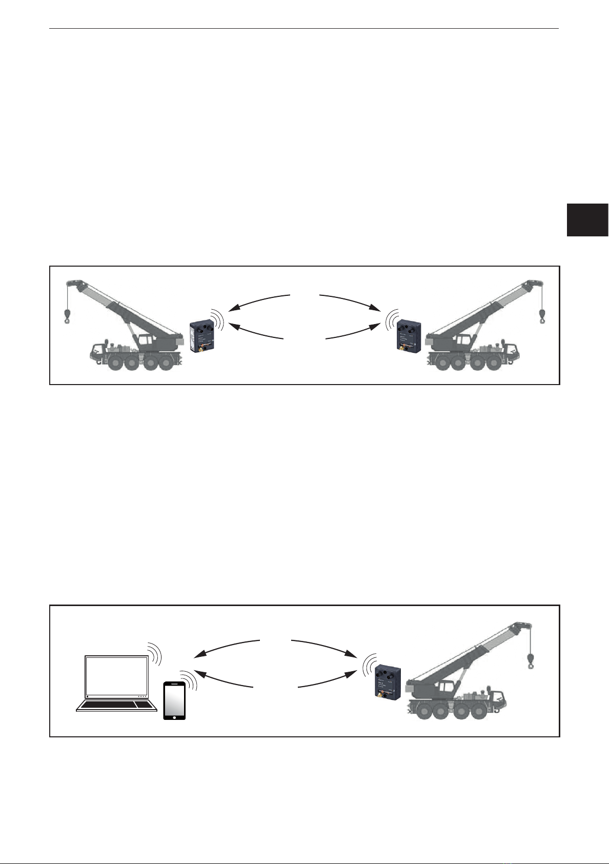
3 Functions and features � � � � � � � � � � � � � � � � � � � � � � � � � � � � � � � � � � � � � � � � � � � � 7
3�1 Overview of the functions � � � � � � � � � � � � � � � � � � � � � � � � � � � � � � � � � � � � � � 8
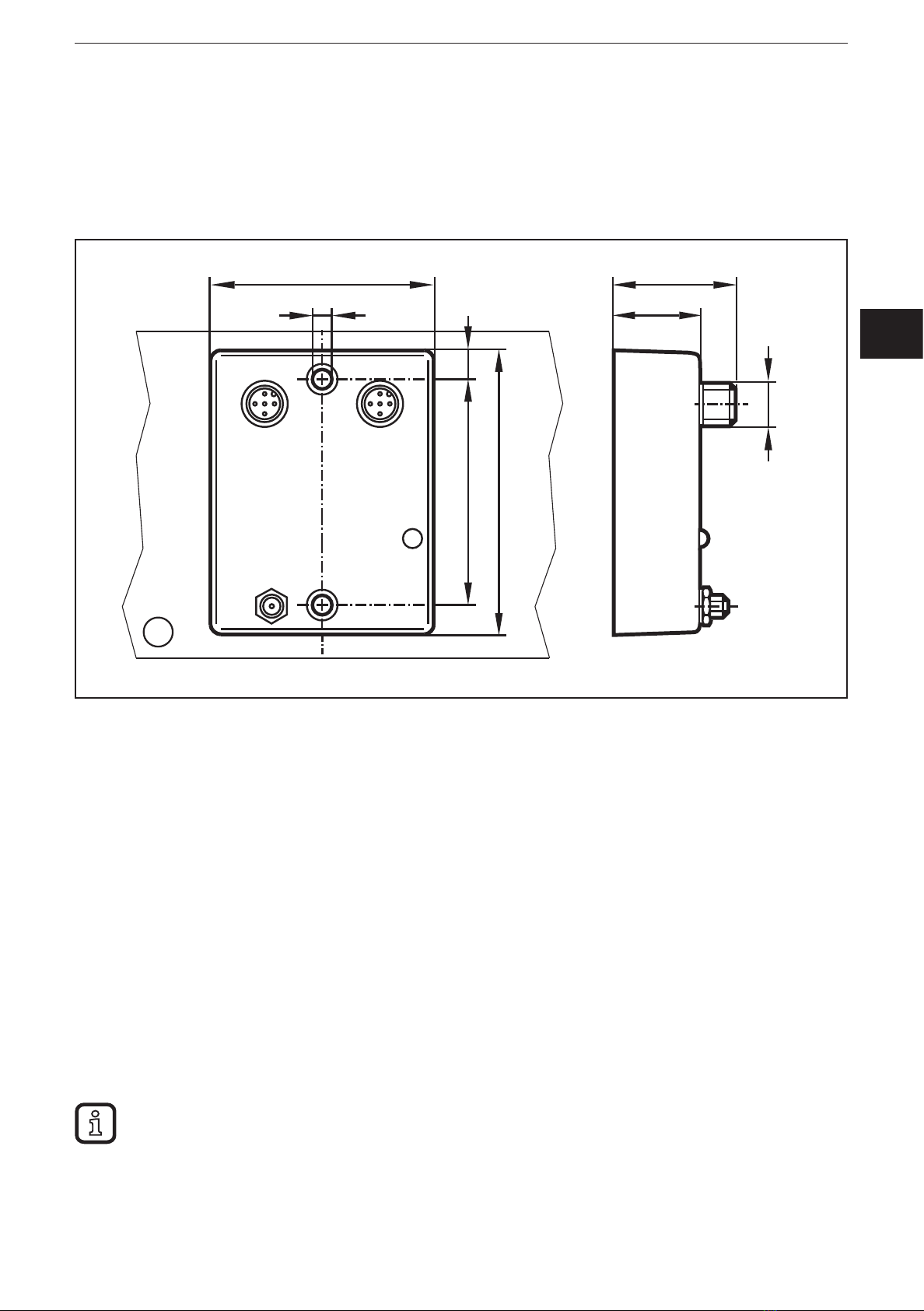
4 Installation� � � � � � � � � � � � � � � � � � � � � � � � � � � � � � � � � � � � � � � � � � � � � � � � � � � � � � 9
4�1 Fixing the device � � � � � � � � � � � � � � � � � � � � � � � � � � � � � � � � � � � � � � � � � � � � 9
4�2 Mounting the antennas� � � � � � � � � � � � � � � � � � � � � � � � � � � � � � � � � � � � � � � � 9
5 Electrical connection� � � � � � � � � � � � � � � � � � � � � � � � � � � � � � � � � � � � � � � � � � � � � 10
5�1 Connectors � � � � � � � � � � � � � � � � � � � � � � � � � � � � � � � � � � � � � � � � � � � � � � � � 10
5�2 Operating voltage and CAN interface� � � � � � � � � � � � � � � � � � � � � � � � � � � � 10
5�3 Service interface� � � � � � � � � � � � � � � � � � � � � � � � � � � � � � � � � � � � � � � � � � � � �11
5�4 Wi-Fi / Bluetooth antenna (art� no� EC2118, only for CR3131) � � � � � � � � �11
6 Indicators � � � � � � � � � � � � � � � � � � � � � � � � � � � � � � � � � � � � � � � � � � � � � � � � � � � � � 12
6�1 LEDs� � � � � � � � � � � � � � � � � � � � � � � � � � � � � � � � � � � � � � � � � � � � � � � � � � � � � 12
7 Set-up � � � � � � � � � � � � � � � � � � � � � � � � � � � � � � � � � � � � � � � � � � � � � � � � � � � � � � � � 13
7�1 Necessary components � � � � � � � � � � � � � � � � � � � � � � � � � � � � � � � � � � � � � � 13
7�1�1 Hardware � � � � � � � � � � � � � � � � � � � � � � � � � � � � � � � � � � � � � � � � � � � � � 13
7�1�2 Software� � � � � � � � � � � � � � � � � � � � � � � � � � � � � � � � � � � � � � � � � � � � � � 13
7�1�3 Documentation� � � � � � � � � � � � � � � � � � � � � � � � � � � � � � � � � � � � � � � � � 13
7�2 Connect the device� � � � � � � � � � � � � � � � � � � � � � � � � � � � � � � � � � � � � � � � � � 13
7�3 Wi-Fi interface � � � � � � � � � � � � � � � � � � � � � � � � � � � � � � � � � � � � � � � � � � � � � 14
7�4 Wi-Fi configuration � � � � � � � � � � � � � � � � � � � � � � � � � � � � � � � � � � � � � � � � � � 14
7�4�1 Wi-Fi mini access point mode � � � � � � � � � � � � � � � � � � � � � � � � � � � � � 14
7�4�2 Wi-Fi infrastructure mode� � � � � � � � � � � � � � � � � � � � � � � � � � � � � � � � � 15
7�5 Bluetooth interface � � � � � � � � � � � � � � � � � � � � � � � � � � � � � � � � � � � � � � � � � � 15
7�6 Bluetooth configuration� � � � � � � � � � � � � � � � � � � � � � � � � � � � � � � � � � � � � � � 16
8 Technical data� � � � � � � � � � � � � � � � � � � � � � � � � � � � � � � � � � � � � � � � � � � � � � � � � � 17
8�1 CR3130 � � � � � � � � � � � � � � � � � � � � � � � � � � � � � � � � � � � � � � � � � � � � � � � � � � 17
8�2 CR3131 � � � � � � � � � � � � � � � � � � � � � � � � � � � � � � � � � � � � � � � � � � � � � � � � � � 19
9 Maintenance, repair and disposal� � � � � � � � � � � � � � � � � � � � � � � � � � � � � � � � � � � 21
9�1 Servicing� � � � � � � � � � � � � � � � � � � � � � � � � � � � � � � � � � � � � � � � � � � � � � � � � � 21
9�2 Cleaning the housing surface� � � � � � � � � � � � � � � � � � � � � � � � � � � � � � � � � � 21

UK
Installation instructions CANwireless CR3130/CR3131
3
9�3 Repair� � � � � � � � � � � � � � � � � � � � � � � � � � � � � � � � � � � � � � � � � � � � � � � � � � � � 21
9�4 Disposal � � � � � � � � � � � � � � � � � � � � � � � � � � � � � � � � � � � � � � � � � � � � � � � � � � 21
10 Approvals/standards � � � � � � � � � � � � � � � � � � � � � � � � � � � � � � � � � � � � � � � � � � � � 21
11 Appendix � � � � � � � � � � � � � � � � � � � � � � � � � � � � � � � � � � � � � � � � � � � � � � � � � � � � � 21
11�1 Wi-Fi encryption � � � � � � � � � � � � � � � � � � � � � � � � � � � � � � � � � � � � � � � � � � � 21
11�2 Wi-Fi frequencies and channels � � � � � � � � � � � � � � � � � � � � � � � � � � � � � � � 21
11�3 Object directory � � � � � � � � � � � � � � � � � � � � � � � � � � � � � � � � � � � � � � � � � � � 23
This document is the original instructions�
Licences and trademarks
All trademarks and company names used are subject to the copyright of the respective companies�

Installation instructions CANwireless CR3130/CR3131
4
1 Preliminary note
This document applies to devices of the type "CANwireless" (art� no�: CR3130 and
CR3131)�
Read this document before use to familiarise yourself with operating conditions,
installation and operation� Keep this document during the entire duration of use of
the device�
Adhere to the safety instructions�
1.1 Symbols used
►Instructions
> Reaction, result
[…] Designation of keys, buttons or indications
→Cross-reference
Important note
Non-compliance may result in malfunction or interference�
Information
Supplementary note
1.2 Warnings used
WARNING
Warning of serious personal injury�
Death or serious irreversible injuries may result�
CAUTION
Warning of personal injury�
Slight reversible injuries may result�
NOTE
Warning of damage to property�

UK
Installation instructions CANwireless CR3130/CR3131
5
2 Safety instructions
These instructions are an integral part of the device� They contain information
and illustrations about the correct handling of the device and must be read before
installation or use�
2.1 General
Follow the operating instructions� Non-observance of the instructions, operation
which is not in accordance with use as prescribed below, wrong installation or
incorrect handling can affect the safety of operators and machinery
Disconnect the device externally before handling it�
In case of malfunction of the device or queries please contact the manufacturer�
Any tampering with the device can seriously affect the safety of operators and
machinery� This is not permitted and leads to an exclusion of liability and warranty�
2.2 Target group
These instructions are intended for authorised persons according to the EMC
and low-voltage directives� The device must be installed, connected and put into
operation by a qualified electrician�
2.3 Electrical connection
The device is designed for supply via a mobile on-board system (12/24 V DC
battery operation)�
The connection terminals may only be supplied with the signals indicated in the
technical data and/or on the device label and only the approved accessories of ifm
electronic may be connected�
2.4 Air traffic
The device must not be operated on board aircraft�
Using it in an aircraft can affect the navigation and communication systems� An
offence can lead to legal action against the offender�
2.5 Explosive substances
In general, radio equipment must not be used in the vicinity of petrol stations, fuel
depots, chemical plants or blasting operations�
Do not transport and store any flammable gases, liquids or explosive substances
in the part of the vehicle where the device is installed�
2.6 Electronic devices
Operation can affect the function of electronic devices that are not correctly
shielded�
Disconnect the unit in the vicinity of medical equipment� Please contact the
manufacturer of the device in case of problems�

Installation instructions CANwireless CR3130/CR3131
6
2.7 FCC (USA)
This device complies with Part 15 of the FCC Rules�
Operation presupposes the two following conditions:
(1) This device must not cause harmful interference, and
(2) this device must tolerate interference including interference possibly causing
undesired operation�
Cautionary Information:
Any changes made to this device without express consent of ifm electronic gmbh
may invalidate FCC approval to operate this device�

UK
Installation instructions CANwireless CR3130/CR3131
7
3 Functions and features
CANwireless allows wireless access to the CAN interface of mobile machines for
data exchange or error diagnostics�
The CR3130 device has an internal antenna� CR3131 has a connection for an
external antenna providing a longer range�
The parameter of the devices are set via the CAN interface�
The following functions are available:
●Wireless CAN bridge:
Direct wireless CAN connection between 2 CAN buses via the CANwireless
devices (Wi-Fi or Bluetooth at option)�
CANwireless CANwireless
WLAN
Bluetooth
Data exchange via wireless CAN bridge
●CAN Wi-Fi / CAN Bluetooth interface:
Wireless CAN connection to other Wi-Fi-capable or Bluetooth devices such
as smartphones, tablets or laptops on which the CAN data is recorded and
evaluated�
Use as Wi-Fi interface is possible in the following operating modes:
– Infrastructure mode
Wi-Fi connection via an existing network�
– Mini access point mode
The device is a Wi-Fi access point and provides its own network�
CANwireless
WLAN
Bluetooth
Wi-Fi / Bluetooth interface

Installation instructions CANwireless CR3130/CR3131
8
CANwireless WLAN
WLAN
WLAN
WLAN
CANwireless
CANwireless
CANwireless
Infrastructure mode
WARNING
The device is not approved for safety-related tasks in the field of operator
protection�
It is, however, permitted to download safety software via this device to provide it
to other devices for installation�
3.1 Overview of the functions
●Integration into a machine network via CAN interface
●Provision of its own network, function as Wi-Fi access point
●Real-time diagnostics via CODESYS programming system
●ServiceTool (visualisation tool)

UK
Installation instructions CANwireless CR3130/CR3131
9
4 Installation
4.1 Fixing the device
►Use 2 M4 x 25 cylinder head bolts (to DIN 912) and 2 tooth lock washers for
M4 (to DIN 6797) to fix the device on an even surface�
1
8
75
59
59 33,5
23,5
4,3
M12x1
Installation (figure shows CR3131 CANwireless)
1: Mounting surface
4.2 Mounting the antennas
Wi-Fi /Bluetooth planar antenna for the CR3131 device: art� no� EC2118
►When mounting the antennas in vehicles avoid the vicinity of fuel tanks,
vessels with explosives or insufficiently screened electronic components (→ 2
Safety instructions)�
►Position the antennas so that a permanent distance of min� 0�2 m from people
is ensured during operation�
►Do not install the antennas in closed metal constructions such as the driver's
cab�
►Please observe the notes of the antenna manufacturer�
Stable data transmission requires a good antenna signal� In case of
problems change the position of the antennas or the mobile equipment if
necessary�
A loosely tightened antenna connector also causes signal loss�

Installation instructions CANwireless CR3130/CR3131
10
5 Electrical connection
5.1 Connectors
2
1
3
2
1
CR3130 CR3131
1: Operating voltage and CAN interface
2: Service interface
1: Operating voltage and CAN interface
2: Service interface
3: RP-SMA socket for Wi-Fi / Bluetooth antenna
NOTE
IP 65 or IP 67 is only ensured if all connectors are connected or protective caps
are screwed onto the sensor�
5.2 Operating voltage and CAN interface
No standard pin connection (see table below)
M12 connector (5 poles) Pin Potential
4
2 1
3
5
Operating voltage 1 GND
2 6���32 V DC
3 Not connected
CAN interface 4 CAN_H
5 CAN_L
NOTE
To avoid damage to the device, connect/disconnect the M12 connector only if
the device is disconnected from power�

UK
Installation instructions CANwireless CR3130/CR3131
11
5.3 Service interface
The service interface is mainly used for factory configuration of the device and
firmware update�
M12 connector (5 poles) Pin Potential
4
2 1
3
5
1 GND
2 Not connected
3 DTR (boot)
4 RxD (input)
5 TxD (output)
5.4 Wi-Fi / Bluetooth antenna (art. no. EC2118, only for CR3131)
NOTE
Only connect or remove antennas if the device is disconnected from power� Put
the device into operation with connected antennas only�
►Do not extend or shorten the antenna cable�
►Please observe the notes of the antenna manufacturer�
RP-SMA socket Pin Potential
Signal 1 Wi-Fi / Bluetooth
GND 2 Screen/housing

Installation instructions CANwireless CR3130/CR3131
12
6 Indicators
6.1 LEDs
11
CR3130 CR3131
1: Status LED 1: Status LED
Colour State Description
Off No data is transmitted / received or no voltage supply
Green On Wi-Fi or Bluetooth connection active
Flashing Ready for Wi-Fi or Bluetooth connection
Bluetooth connection is established
Device initialisation
Reset status
Red On CAN error, critical voltage
Flashing Device ready for reset to factory settings
CAN data transfer
Orange On Configuration mode or firmware update

UK
Installation instructions CANwireless CR3130/CR3131
13
7 Set-up
7.1 Necessary components
The following components are needed to configure and set up the device:
7.1.1 Hardware
●CR313x CANwireless
Ensure that all components necessary for the device configuration are used (→
7�2 Connect the device)�
●CANwireless antenna (art� no� EC2118, only for CR3131)
●PC
●CAN/PC interface (e�g� CAN/RS232 USB interface CANfox, art� no�: EC2112)
● CAN bus terminating resistors (2 x 120 Ω)
7.1.2 Software
Device configuration
●ifm maintenance tool as from version V02�02�13
Device integration into the application program
●CODESYS programming system
●CANremote CODESYS client/gateway (optional)
●Electronic data sheet (EDS) (optional)
7.1.3 Documentation
●CODESYS programming manual
(alternatively as online help)
●System manual of the controller used
(alternatively as online help)
The manuals are available on the internet in PDF format by entering the
corresponding article number:
www.ifm.com → Data sheet search → Article number → More information
Software, function libraries and manuals (as online help):
www.ifm.com → Service → Download → Systems for mobile machines*
*) Download area with registration
7.2 Connect the device
►Connect the CANwireless antenna to the device (only CR3131)�
► Provide the CAN bus with 120 Ω terminating resistors.
►Connect the CAN/PC interface with the CAN adapter cable to the device and
connect it to the PC�
►Apply the supply voltage�

Installation instructions CANwireless CR3130/CR3131
14
7.3 Wi-Fi interface
The use as Wi-Fi interface allows wireless transfer of CAN data to other Wi-Fi
capable devices such as PCs, smartphones or tablets on which CAN data can be
recorded and evaluated�
The device can be integrated in the existing network infrastructure (infrastructure
mode)� In the mini access point mode the device can assume the function of
a Wi-Fi router and provide a wireless network for other Wi-Fi capable devices
in the infrastructure mode� The network parameters can then be provided by
CANwireless via DHCP server�
Data is exchanged bidirectionally as soon as the software has established a
connection to the device�
The ifm maintenance tool is used for the configuration via the CAN interface�
7.4 Wi-Fi configuration
The use as Wi-Fi bridge ensures wireless transfer of CAN data between two CAN
bus systems� In this case, two CANwireless devices replace the CAN cable�
To use two devices as Wi-Fi bridge, one device must be configured as slave and
one device as master� The device is configured as slave by the factory�
The ifm maintenance tool can be used for the configuration�
7.4.1 Wi-Fi mini access point mode
Configuration device 1 (master):
In the Wi-Fi bridge mode some of the data entered here is also required for
the configuration of device 2 (slave)�
►Deactivate Bluetooth under "Bluetooth settings"�
►Activate Wi-Fi under "WLAN settings"�
►Select "Mini AP" under "Operating mode"�
►Enter a network name under "SSID"�
►Select the Wi-Fi encryption under "Authentication type" which complies with the
required safety criteria and enter the respective data�
►Select the required frequency, channel and data rate under "Access Point
Settings"�
►Select the DHCP mode "Server" under IP settings�
►Enter the desired host name (may be identical with the SSID)�
►Activate "Socket Server"�
►Enter the requested port under "Port number"�
►Select the requested communication protocol under "Protocol"�

UK
Installation instructions CANwireless CR3130/CR3131
15
►Deactivate "Automatic socket connection"�
►Transfer the configuration to device 1�
7.4.2 Wi-Fi infrastructure mode
Configuration device 2 (slave):
►Deactivate Bluetooth under "Bluetooth settings"�
►Activate Wi-Fi under "WLAN settings"�
►Select the "Infrastructure" operating mode under "Operating mode"�
►Enter the network name configured in device 1 under "SSID"�
►Select the Wi-Fi encryption configured in device 1 and enter the respective
data�
►Select the DHCP mode "Client"�
►Enter the requested host name� (Must not be identical with the host name of
device 1�)
►Deactivate "Socket Server"�
►Activate "Automatic socket connection"�
►Enter the IP address of device 1 under "Remote address"
(default value: 192�168�82�246)�
►Enter the data configured in device 1 under "Port number" and "Protocol"�
►Transfer the configuration to device 2�
The connection between a configured master and slave device is made
automatically after power-on� Data is exchanged bidirectionally as soon as the
connection between the two devices has been established�
7.5 Bluetooth interface
The use as Bluetooth interface allows wireless transfer of CAN data to other
Bluetooth capable devices such as PCs, smartphones or tablets on which CAN
data can be recorded and evaluated� Data is exchanged bidirectionally as soon as
the software has established a connection to the device�
The ifm maintenance tool is used for the configuration via the CAN interface�

Installation instructions CANwireless CR3130/CR3131
16
7.6 Bluetooth configuration
For a Bluetooth bridge the slave configuration should be made first� For the slave
configuration the Bluetooth MAC address and the pin code of the master device
are required�
Configuration device 1 (master):
►Deactivate "Wi-Fi" under "WLAN settings"�
►Activate Bluetooth under "Bluetooth settings"�
►Enter a device name under "Device name"�
►Activate "Discoverable" and "Pairable"�
►Set the parameter "Security mode Bluetooth 2�1" under "Security settings" to
"Disable"�
►Activate "Allow Bluetooth 2�0 pairing"�
►Enter a four-digit code under "Pin code"�
►Deactivate "Automatic Bluetooth Connection"�
►Activate "SPP Server"�
►Transfer the configuration to device 1�
►Take down the Bluetooth MAC address of the master device (can be found on
the housing)�
Configuration device 2 (slave):
►Deactivate "Wi-Fi" under "WLAN settings"�
►Activate Bluetooth under "Bluetooth settings"�
►Enter a device name under "Device name"�
►Activate "Discoverable" and "Pairable"�
►Set the parameter "Security mode Bluetooth 2�1" under "Security settings" to
"Disable"�
►Activate "Allow Bluetooth 2�0 pairing"�
►Enter the four-digit code configured in device 1 under "Pin code"�
►Activate "Automatic Bluetooth Connection"�
►Enter the Bluetooth MAC address of the master device under "Bluetooth MAC
address"�
►Deactivate "SPP Server"�
►Transfer the configuration to device 2�

UK
Installation instructions CANwireless CR3130/CR3131
17
8 Technical data
8.1 CR3130
Control systems
ifm electronic gmbh • Friedrichstraße 1 • 45128 Essen
We reserve the right to make technical alterations without prior notice! 23�09�2016CR3130 / page 1
CR3130
Original Scale Drawing (MTD)
EPS Source
Product Scale Drawing
Frame Size: 80 mm x 40,5 mm
P_MZ_e100_0091
8
75
59
59 33,5
23,5
4,3
LED
M12x1
8
75
59
59 33,5
23,5
4,3
LED
M12x1
CANwireless
with integrated antenna
CAN Wi-Fi/Bluetooth
interface
Wi-Fi frequency bands
2�4 GHz and 5 GHz
8���32 V DC
Technical data
Electrical data
Operating voltage U
B
8���32 V DC
Current consumption ≤ 60 mA (at 24 V DC)
Status LED 1 x 2 colours (red / green)
CAN interface
Profi le CAN interface 2�0 A/B, ISO 11898-2
Protocol CANopen, CAN Layer 2, J1939
CAN receive buffer 2048 messages
CAN to Wi-Fi buffer size 2048 messages
Wi-Fi
Frequency band 2�4 / 5 GHz
Protocol IEEE 802�11 a/b/g/n, IEEE 802�11 d/e/i/h
Safety standard WPA2-PSK, WPA-PSK, WEP64, WEP128, LEAP, PEAP
Range ≤ 75 m
Functions Wi-Fi bridge (infrastructure mode)
Wi-Fi interface (infrastructure mode or mini access point mode)
Transmission rate
1)
1600 CAN messages per second
Average latency time
2)
≤ 20 ms (Wi-Fi bridge)
Bluetooth
Standard Bluetooth Classic (2�1 + EDR)
Profi le SPP (Serial Port Profi le)
Range ≤ 75 m
Functions Bluetooth bridge
Bluetooth interface
Transmission rate
1)
4000 CAN messages per second
Average latency time
2)
≤ 20 ms (Bluetooth bridge)

Installation instructions CANwireless CR3130/CR3131
18
ifm electronic gmbh • Friedrichstraße 1 • 45128 Essen
We reserve the right to make technical alterations without prior notice! 23�09�2016CR3130 / page 2
CR3130 Technical data
Control systems
Software
Device confi guration ifm maintenance tool or CODESYS with EDS fi le
Remark For more information see www.ifm.com → CR3130
Mechanical data
Ambient temperature -30���75 °C
Protection rating IP 67
Housing material polyamide (black)
Weight 0�060 kg
Test standards and regulations
CE EN 60950-1
EN 301489-1 V1�9�2
EN 301489-17 V2�2�1
EN 61000-6-2
EN 61000-6-3
EN 300328 V1�9�1
EN 301893 V1�8�1
E1 UN/ECE-R10
FCC FCC Part 15/47 CFR Conducted Limits
FCC Part 15/47 CFR Radiated Emission Limits
regarding Part 15 of the FCC rules (Class B digital devices)
Wiring
CAN / supply
M12 connector, 5 poles
4
2 1
3
5
1
2
3
4
5
GND
U
B
Not connected
CAN_H
CAN_L
Ground
Supply
Not connected
CAN interface (high)
CAN interface (low)
RS-232
M12 connector, 5 poles
4
2 1
3
5
1
2
3
4
5
GND
Not connected
DSR
RxD
TxD
Ground
Not connected
Data Set Ready (boot)
RS-232 receive (input)
RS-232 transmit (output)
Remarks
1)
for CAN messages and 1 MBit/s
2)
for transmission of a single CAN message

UK
Installation instructions CANwireless CR3130/CR3131
19
8.2 CR3131
Control systems
ifm electronic gmbh • Friedrichstraße 1 • 45128 Essen
We reserve the right to make technical alterations without prior notice! 23�09�2016CR3131 / page 1
CR3131
Original Scale Drawing (MTD)
EPS Source
Product Scale Drawing
Frame Size: 80 mm x 40,5 mm
P_MZ_e100_0090
1
8
75
59
59 33,5
23,5
4,3
LED
M12x1
1
8
75
59
59 33,5
23,5
4,3
LED
M12x1
CANwireless
for connection to an
external antenna
CAN Wi-Fi/Bluetooth
interface
Wi-Fi frequency bands
2�4 GHz and 5 GHz
8���32 V DC
Technical data
Electrical data
Operating voltage U
B
8���32 V DC
Current consumption ≤ 60 mA (at 24 V DC)
Status LED 1 x 2 colours (red / green)
CAN interface
Profi le CAN interface 2�0 A/B, ISO 11898
Protocol CANopen, CAN Layer 2, J1939
CAN receive buffer 2048 messages
CAN to Wi-Fi buffer size 2048 messages
Wi-Fi
Frequency band 2�4 / 5 GHz
Protocol IEEE 802�11 a/b/g/n, IEEE 802�11 d/e/i/h
Safety standard WPA2-PSK, WPA-PSK, WEP64, WEP128, LEAP, PEAP
Range
1)
≤ 200 m
Functions Wi-Fi bridge (infrastructure mode)
Wi-Fi interface (infrastructure mode or mini access point mode)
Transmission rate
2)
1600 CAN messages per second
Average latency time
3)
≤ 20 ms (Wi-Fi bridge)
Bluetooth
Standard Bluetooth Classic (2�1 + EDR)
Profi le SPP (serial port profi le)
Range
1)
≤ 100 m
Functions Bluetooth bridge
Bluetooth interface
Transmission rate
2)
4000 CAN messages per second
Average latency time
3)
≤ 20 ms (Bluetooth bridge)
1: RP-SMA socket

Installation instructions CANwireless CR3130/CR3131
20
ifm electronic gmbh • Friedrichstraße 1 • 45128 Essen
We reserve the right to make technical alterations without prior notice! 23�09�2016CR3131 / page 2
CR3131 Technical data
Control systems
Software
Device confi guration ifm maintenance tool or CODESYS with EDS fi le
Remark For more information see www.ifm.com → CR3131
Mechanical data
Ambient temperature -30���75 °C
Protection rating IP 65
Housing material polyamide (black)
Weight 0�065 kg
Test standards and regulations
CE EN 60950-1
EN 301489-1 V1�9�2
EN 301489-17 V2�2�1
EN 61000-6-2
EN 61000-6-3
EN 300328 V1�9�1
EN 301893 V1�8�1
E1 UN/ECE-R10
FCC FCC Part 15/47 CFR Conducted Limits
FCC Part 15/47 CFR Radiated Emission Limits
regarding Part 15 of the FCC rules (Class B digital devices)
Wiring
CAN / supply
M12 connector, 5 poles
4
2 1
3
5
1
2
3
4
5
GND
U
B
Not connected
CAN_H
CAN_L
Ground
Supply
Not connected
CAN interface (high)
CAN interface (low)
RS-232
M12 connector, 5 poles
4
2 1
3
5
1
2
3
4
5
GND
Not connected
DSR
RxD
TxD
Ground
Not connected
Data Set Ready (boot)
RS-232 receive (input)
RS-232 transmit (output)
Wi-Fi antenna
RP-SMA socket
1)
1
2
Signal
GND
Wi-Fi / Bluetooth
Ground
Remarks
1)
with / for antenna article no� EC2118
2)
for CAN messages and 1 MBit/s
3)
for transmission of a single CAN message
This manual suits for next models
1
Table of contents
Other IFM Recording Equipment manuals