Actuall DoorLIFT DL-6 User manual
Owner’s Manual
KEEP THIS OWNER’S MANUAL IN VEHICLE
Need help?
For assistance with this product please visit
www.actuall.eu or contact your dealer.
Version 01-2020

2
DoorLIFT DL-6
Remote door system
Index
1Unit informaon 2
2 Safety guidelines 3
3Service book 4
4 Control devices 8
4.1 How does the remote control work 9
4.2 Programming remote control 9
5Inspecon and maintenance shuer door 10
6 Inspecon and maintenance DoorLIFT 12
7Removal motor unit 14
8How to lock the gears 16
9How to adjust the sensor 17
10 Emergency release 18
11 Basic trouble shoong 19
12 Changing DL-8001252 Tooth wheel (24) 20
13 Technical specicaons 22
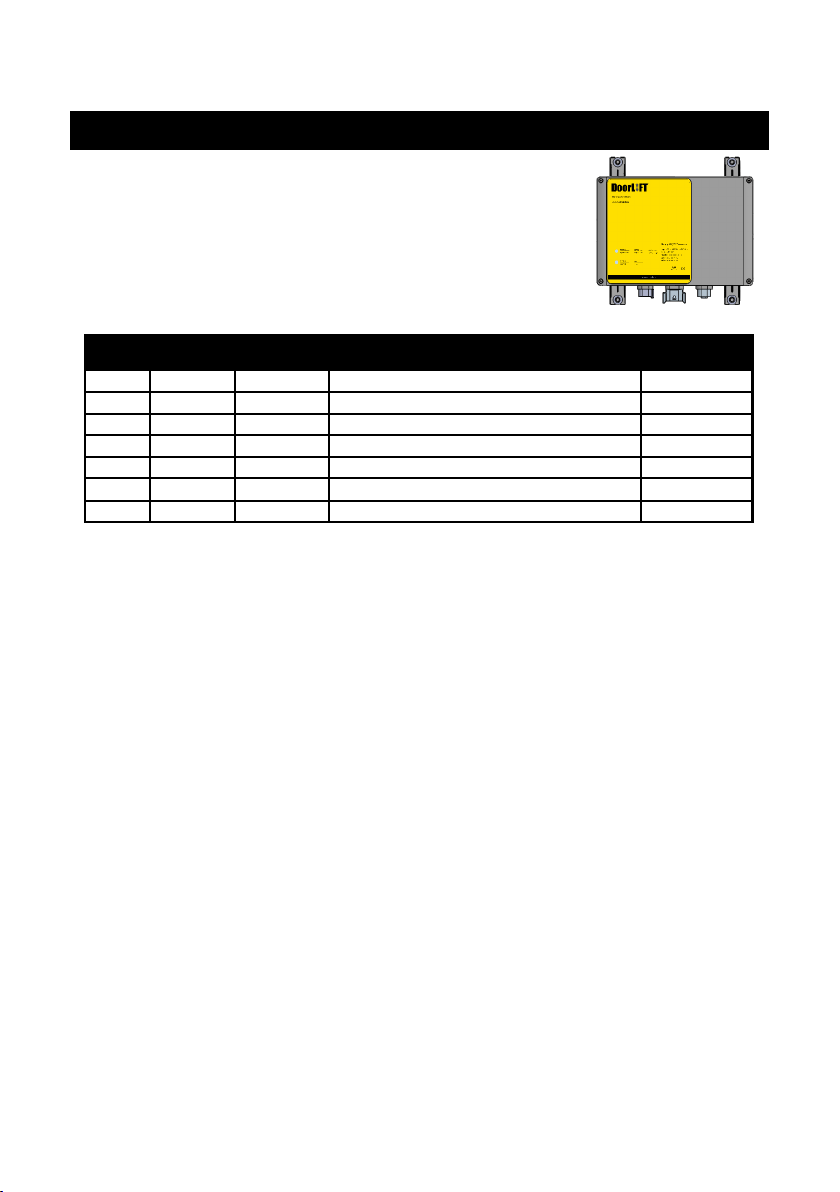
DoorLIFT serial no.
Dealer
Installaon date
Door type
Door size
Door serial number
1. Unit informaon
Owner’s manual
3
DoorLIFT DL-6
Remote door system
Owner’s manual
2. Safety guidelines
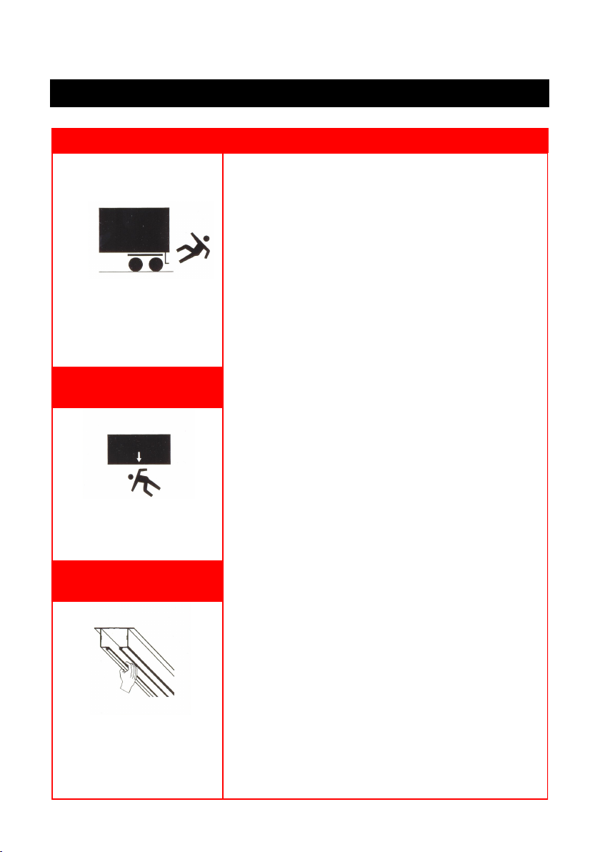
Warning Safety guidelines
Aenon: Risk of injuries!
Aenon: Risk of injuries!
Never put your ngers into the
track of the door or into the pro-
le of the DoorLIFT.
Nothing should be in the range of
the shuer door when it is mo-
ving.
Slipping, tripping or falling on or
of the oor of the lorry’s goods
compartement can cause injury.
For problem-free operaon of the DoorLIFT, the lorry’s shuer door
must always be kept in good condion.
Before using the DoorLIFT:
1. Check if all the shuer doors components are rmly in
place. Loose parts must be xed or replaced if necessary.
2. Check the lorry’s shuer door is working properly.
When using the DoorLIFT:
1. No obstacles are allowed in the range of the shuer door
when it is moving!
2. If the door can be locked of bolted, do not forget to unlock
or unbolt it.
3. Check the movement of the DoorLIFT both on opening and
closing. If the DoorLIFT runs unevenly, invesgate the
cause and repair it if possible.
4. Replace damaged parts as quickly as possible.
5. Recurring stoppages or problems must be sorted out as
quickly as possible by people with the appropriate training.
Do not aempt to resolve problems yourself if you do not
have the proper training. Electronic equipment requires
specialised knowledge.
6. Take care that the rails in the doors range of movement
are not blocked.
Aer using the DoorLIFT:
1. The door should be closed properly before driving away.
2. Never drive with an open door; this will damage the Door-
LIFT.
Maintenance:
1. Damaged, loose or missing parts should be repaired or
replaced by skilled personnel. You should have checked the
DoorLIFT at least twice a year.
2. When repairing the DoorLIFT you should always disconnect
the system from the power supply.
Aenon: Electronic equipment requires specialised knowledge!
3. Do not lubricate the DoorLIFT.
4. Clean using a damp cloth. Do not use any volale substanc-
es as stac electricity may ignite them and causes an explo-
sion.
5. Use genuine DoorLIFT replacement parts.

4
3. Service Book
Type of service Date By
Notes
DoorLIFT DL-6
Remote door system
Owner’s manual
Type of service Date By
Notes
Type of service Date By
Notes
5
DoorLIFT DL-6
Remote door system
Owner’s manual
Type of service Date By
Notes
Type of service Date By
Notes
Type of service Date By
Notes

6
Type of service Date By
Notes
DoorLIFT DL-6
Remote door system
Owner’s manual
Type of service Date By
Notes
Type of service Date By
Notes

7
DoorLIFT DL-6
Remote door system
Owner’s manual
Type of service Date By
Notes
Type of service Date By
Notes
Type of service Date By
Notes
Make a copy of this page rst, this is the last blank sheet

8
DoorLIFT DL-6
Remote door system
Owner’s manual
4. Control devices
Your DoorLIFT system may be supplied with two wireless key FOB transmiers. Any
other external device like switches are provided by the er or customer.
Item Descripon Funcon
1Remote control Up/down automac
2Push buon single Up/down automac
3Push buon up Up automac
4Push buon down Down automac
5Block funcon Automac close door, block all input
Oponal funcons:
Connect auxiliary devices to the DoorLIFT control box
through the 8-lead harness using the wire chart below.
Wire Item
1Up/down input
2Up input
3Down input
4Signal block (ignion lockout)
5+ 12V output (max 250 mA)
6Door ajar output (ground)
7Cargo light output (ground)
Yellow/green Ground (max 250 mA)
The 8-pin female connector on the box comes equipped
with a plug to protect the connector from water and dirt if
the harness is not used. This plug is removed and discarded
if the harness is ulized.
1.
2.

9
4.1 How does the remote control work
When a command is given, the LED’s will indicate the signal
was received.
- LED 2 on the control box will momentarily ash orange, as an
input signal is received either from a FOB or a switch.
- LED 1 will start to ash green as 32 VDC is sent to the motor
LED indicator
4.2 Programming remote control
2
1
1. When the power is turned on by connecng
the baery cable to the control box, within 5
seconds, press the buon 1 and 2 at the same
me. The system will then enter the code learn-
ing mode. The UNLOCK OUTPUT will trigger to
remind you that the system is in code learning
mode.
2. Within 5 seconds aer entering the code
learning mode, press any buon on the trans-
mier. The UNLOCK OUTPUT will trigger to tell
you the transmier has been recognized and is
compable with the system. A maximum of 12
transmiers can be coded per system.
3. During code learning, if there is no acon
aer 5 seconds, the system will exit learning
mode. The UNLOCK OUTPUT will be the remind-
er.
4. If old FOBs have to be erased from the re-
ceiver’s memory for any reason, program the
new FOBs with the above procedure and don’t
include the old FOBs in this procedure. This
process will erase the old FOB data from the
receiver’s memory.
DoorLIFT DL-6
Remote door system
Owner’s manual
Note: if the FOB baery
has to be replaced for any
reason, the baery is a 12
Volt A-23 dry cell type
10
5. Inspecon and maintenance shuer door
Maintain the shuer door every 3 months:
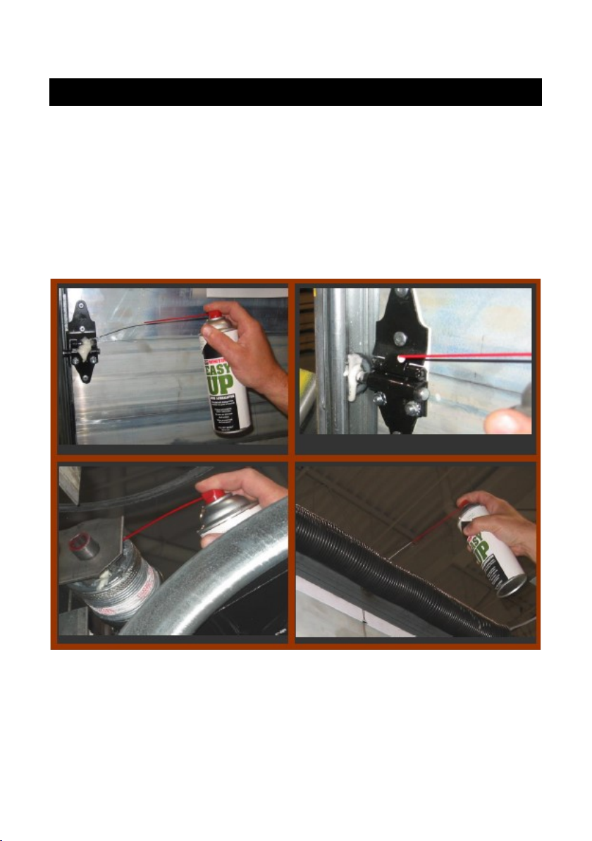
1. Lubricaon shuer door
2. Balancer maintenance and adjustment
3. Check if all the shuer doors components are rmly in place.
1. Lubricate the roller bearings and shas, hinge pins and cable drum bearings as
per the illustraon below.
DO NOT USE GREASE OF ANY KIND
Grease sits on the surfaces and aracts dust, dirt and salt.
DoorLIFT DL-6
Remote door system
Owner’s manual

11
2. Check to make sure the shuer door is properly balanced.
ALWAYS lubricate your shuer door, prior to checking the balance of the door.
The DoorLIFT will operate the shuer door provided a force of no more than 35Kg
to open or close the door. Ensure that the force required to li the door is equal to
the force required to close the door.
• If the door requires more force to open than it does to close, increase the
tension on the balancer.
• If the door requires more force to close than it does to open, decrease the
tension on the balancer.
Addional info:
Time and the elements aect the tension on the spring that lis the door. Over
me, the spring wire will corrode and loose eecve wire diameter. The springs
themselves also get red and loose their tensile strength. An average balancer on a
door will last approximately 15,000 to 25,000 cycles.
Adjusng and maintaining the proper door balance:
CAUTION—work on doors and related parts can be dangerous. It is strongly recom-
mended that repair service work be preformed by persons who have successfully
completed appropriate training.
1. For adjusng the spring, please consult your shuer manual for brand spe-
cic instrucons.
DoorLIFT DL-6
Remote door system
Owner’s manual

12
6. Inspecon and maintenance DoorLIFT
Pre-condions:
• Maintenance should be performed by qualied (trained) sta.
• Maintenance of the DoorLIFT should always be done in conjuncon with
maintenance of the shuer door.
• Maintenance schedule is based on 40 cycles per day, 5 days a week. At high-
er frequency, you may need to do the inspecon more oen.
• Maintenance schedule is based on a well maintained, well balanced and
manual operable shuer door.
• When repairing the DoorLIFT you should always disconnect the system from
the power supply.
• DO NOT GREASE OR LUBRICATE THE DoorLIFT. Clean using a damp cloth.
• Use only genuine DoorLIFT replacement parts.
DoorLIFT DL-6
Remote door system
Owner’s manual
13
Maintenance acvies Six months Yearly
Check the operaon by opening and closing the system with
the door aached
XX
Check the balancing of the door with the DoorLIFT discon-
nected
XX
Ensure that all parts are properly ghtened. Damaged, loose
or lost parts should be repaired or replaced
XX
Inspect the aluminum track XX
Lubricate and test the emergency unlocking system XX
Perform door maintenance as instructed in Step 5 XX
Check all electrical connecons for ghtness and corrosion X
Disconnect the motor-unit and take it out of the track for
inspecon
X
Do a visual inspecon of the motor-unit gears and guide
wheels
X
Check the cable of the emergency unlocking mechanism
and replace if damaged.
X
Replace the four guiding blocks (part number: DL-8001254). X
Replace the baery of the remote control FOB if needed X
Place service scker X
Expected me for maintenance service of DoorLIFTs excluding door
maintenance and inspecno:
Six months :30 minutes.
Annual :60 minutes.
Replace the motor-unit aer 5 years or 160.000 cycles
DoorLIFT DL-6
Remote door system
Owner’s manual
14
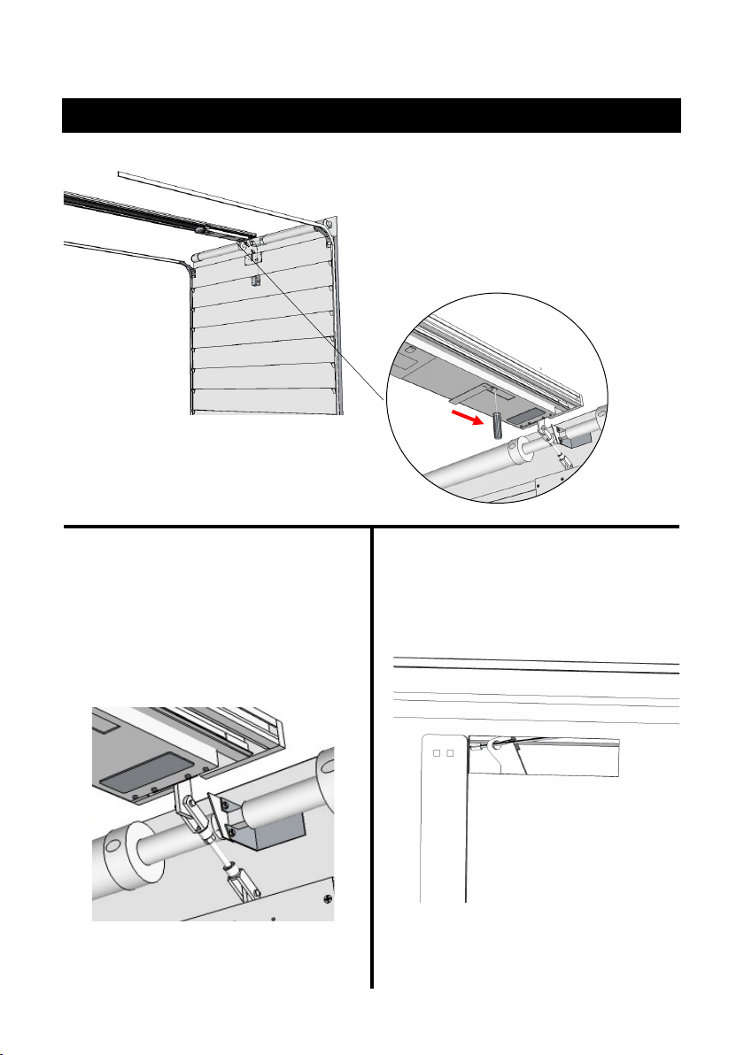
7. Removal motor unit
1. Use a screw driver and insert this in
the lever, located in the motor unit.
Move the lever towards the shuer
door. Your are now able to open and
close the door by hand.
2. Remove the clevis pin on the turn
buckle. This will disconnect the motor-
unit from the door.
3. Remove the cable from the lever
DoorLIFT DL-6
Remote door system
Owner’s manual

15
4. Remove the cable from the cable
tube in the motor-unit.
5. Remove the cover from the track.
6. Cut the zip e retaining the yellow
cable to the slider cover. Unscrew the
slider cover bolts and remove it.
Unplug the yellow cable harness from
the motor connector within the box.
7. Slide the motor-unit out of the
track.
DoorLIFT DL-6
Remote door system
Owner’s manual

16
“click”
Using a screw driver, insert the p in the
lever located in the motor-unit.
Move the lever towards the Baery icon
unl you hear a rm “click” meaning the
gears are meshed with the linear track
gears.
8. How to lock the gears
DoorLIFT DL-6
Remote door system
Owner’s manual
17
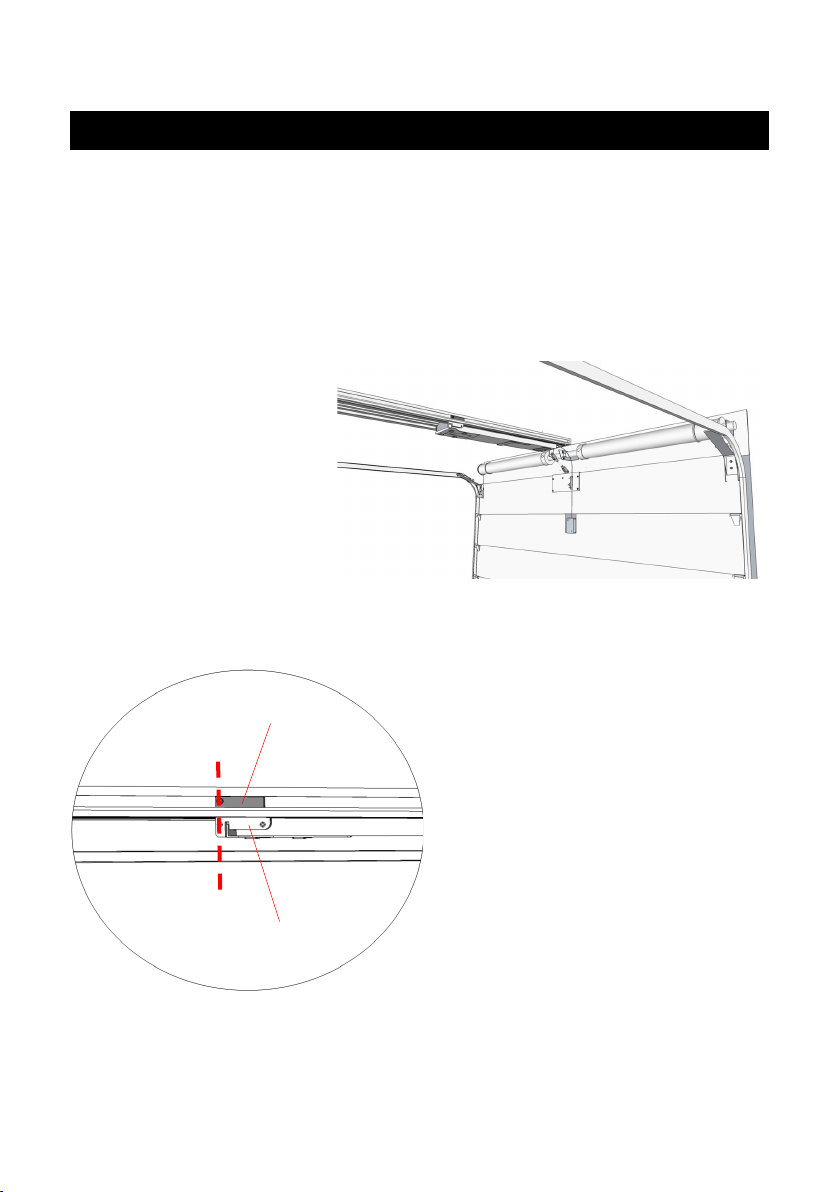
9. How to adjust the sensors
A
B
The sensor switch for the CLOSED posion is set at the factory, but may need ad-
justment depending on the header size and turnbuckle length.
Note: to gain acces to the Close switch, the track trim can be slid on the track to
gain access.
1. Disengage motor. Close
the door fully by hand.
2. Set the sensor (A) sideways to
match the cable slider (B). Both screw
heads should be in line, see picture
The cable slider holds a magnet.
DoorLIFT DL-6
Remote door system
Owner’s manual
18
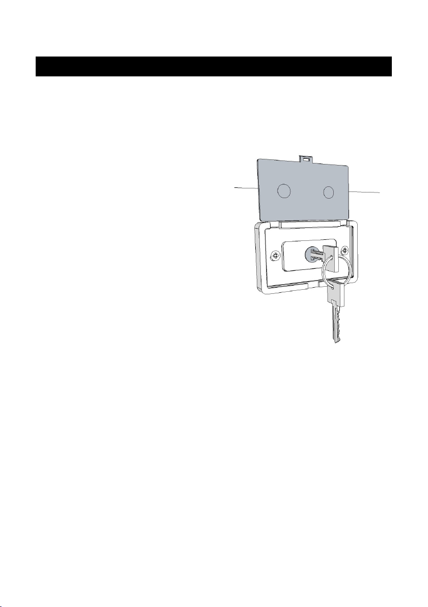
10. Emergency release
You may be occasionally required to release the DoorLIFT from the door, in order to
operate the shuer door manually. DoorLIFT can be released from the drive system
in the following way:
Using the exterior EMERGENCY release
1. Insert the DoorLIFT key into the lock
cylinder located in the center of the
second shuer door panel, on the
outside of the door.
2. Turn the key 90 degrees clockwise
and pull the lock and connecng
cable from the lock cylinder. Pull the
lock assembly rmly and the Door-
LIFT will be released from the drive
system.
3. Reinsert the cable and lock cylinder
back into the lock housing on the
door. The shuer door can now be
operated manually.
DoorLIFT DL-6
Remote door system
Owner’s manual
19
11. Basic trouble shoong
When your system isn't working properly or not at all, pleas check
the following:
1. Check for visible damage or obstrucon
2. Try if a dierent control device is working
3. Check the control box and see what the LED’s are telling you
LED Colour Sequence Issue/Funcon Explanaon
LED 1 Red Flash Low voltage input (during operaon) A
LED 1 Green Solid Power in B
LED 1 Green Flash In operaon C
LED 2 Orange Flash Signal received D
LED 2 Orange Solid Warning, overload motor-unit / obstrucon E
LED 2 Red Solid Error, me out door travel F
LED 1 None NA No input power G
LED Explanaon
A. The input on the systems is too low. Check the voltage and capacity of the baery. Also
check the cables from the baery to the control box for any damage or weary.
B. The control box has a power coming in
C. The control box has received the signal and is sending power out to the motor-unit. If
the motor-unit is sll not running, please see if the power is geng to the motor-unit by
taking of the cap (chapter 7, step 6) and measure the voltage in the connector on the
spiral cable.
Also check the motor-unit for any damage on wiring or gears.
D. The control box has received a signal from the control device. If you are using a remote
control and LED 1 is not starng to ash; try to reprogram the remote control to the
control box rst. If aer that, or when you use push buons, the LED 1 is sll not ash-
ing; the control box is not working.
E. The control box has detected a abnormality in the form of an obstrucon or overload on
the motor-unit. In both case, the currents got too high and the control box shuts o.
Check if there is nothing blocking the door from going up/down.
Check if the door closed sensor is adjusted right and the motor-unit reaches it.
Check if the motor-unit is running with normal speed and doesn't make a strange noise.
These are signs that the motor-unit is damaged and draws too much amperage from the
system.
F. The system took too long to get to the next point in the cycle. This might either be a
slow motor-unit (because the motors are not strong enough anymore) or the system is
not reaching one of the sensors in me.
G. The control box has no input power. Please check the fuse on the baery cable, the
baery and the cable itself.
DoorLIFT DL-6
Remote door system
Owner’s manual

20
12. Changing DL-8002152 Tooth wheel (24)
DoorLIFT DL-6
Remote door system
Owner’s manual
Take o the circlip Take o the tooth
wheel
Place the new tooth
wheel
Return the circlip
1. 2.
3. 4.
For all other repairs, please contact your dealer for support. Do not try to repair
the DoorLIFT by yourself, this requires specic knowledge and training.
Other manuals for DoorLIFT DL-6
1
Table of contents


