Actuator Systems TCR-40C Series Parts list manual

TCR-40C-All Series-Intelligent on/off actuator usage instructions
◎Rated voltage: AC230V【AC95-265V】、AC/DC24V
◎Rated torque: 400N.m[450N.m@Max]
◎Running time: about 25s
◎Install valves: 2-way,3-way ball valve and butterfly valve
◎Wiring and feedback model:B3J、BD3J、B43J、B33J、B44J(J:Relay feedback,
synchronous feedback signal with actual arrival )
◎Alarm output: A(Relay contact feedback)
◎Direction of rotation and angle of rotation: double acting 90°
2 positions 180°, 3 positions or 4 positions
◎
Adopted high-performance brushless motor,Overload protection of internal motor
◎It can be used 20,000 times.*1
◎Two or more actuators can be used in paralle
※ Attention: Don’t use in paralle with Normal on/off actuator under control of the same contactor.
Product overview
Product features
△
0.96” double OLED screen,no visual dead angle,highly bright,energy saving and eco-friendly,real time to
show valve
opening angle and external control command.Enter sleeping state automatically after about
5 minutes,while
it could prompt location state and its control command at sleeping time.
△Original valve adjustment mode-free cover-opening and interactive:
step1:saving “anticlockwise full open position ” by using the button to control valve;
step2:saving “clockwise full close position ” by using the button to control valve;it makes valve adjustment easier.
Thoroughly eliminate the complex and inconvenience caused by mechanical positioning.
△
Adopt 16 High-performance microcontrollers,12 high-precision AD conversion,built-in unique algorithm,
thoroughly eliminate valve on/off inaccuracy caused by mechanical hysteresis,espacially suitable for 3-way
valve adjustment.
△Adopt non contact positioning,control unit moduarize design and potting processing,greatly improve product
service life;Interface uses standard connectors,convenient for installment,adjustment and replacement.
△M
enu can report real time failure,including stuck or other reasons which lead actuator fail to realize valve on/off
integrally,and output failure warning signal.
△Menu can realize valve control command exchange.
△
Menu can switch freely between remote control and local setting,and adopt button to realize valve on/off locally.
△
Menu can set valve close position deviation to on or off direction,thoroughly eliminate the complex and
inconvenience bring by “Normal On/Off mechanical positioning” to local valve adjustment.
△Menu can real-time adjust valve running speed of the actuator.
△Menu can restore factory default setting.
Success comes from our persistent pursue of perfect details.
Excellence originates from our persistence of win-win philosophy.
1
PART 2
User Manual
®
特克
.co
m
Made in china Global service
ISO9001
*1.
Test condition:Rated load,test at under 25℃working temperature and 50% humidity,lead the result from 2 times switching cycle,which will be influenced by different load
and working environment.

TCR-40C-All Series-Intelligent on/off actuator usage instructions
S3-85%(loading ≤85% rated torque refer to IEC60034-1-2017 *1)
*1
Operating mode: The testing environment temperature is 25 ℃ inside the factory. The testing standard as per IEC 60034-1-2017.The operation mode will be S3-90% if fthe
loading less than 60% rated torque..
Technical data
Electrical data
Functional data
Rated voltage
Rated voltage range
Power consumption
Peak current
@Rated Voltage
Fuse
Rated torque
Angle of rotation
Max angle of rotation
Manual operation
Running time
Operating mode
Sound power level
Position indicator
Electricity safety level
Inflaming retarding level
Enclosure
Insulation resistance
Withstand voltage
Medium temperature
Working environment
Explosion-proof level
Ambient temp
Non-operation temp
Humidity
Ambient temperature*2
Working conditions
AC/DC95-265V(50/60HZ)
AC95-265V/DC100-300V
80W@MAX22W@running 5.9W@holding
0.36A/5ms@AC230V
2A
AC/DC24V
AC20-26V/DC22-30V
80W@MAX;19.2W@running 2.4W@holding
3.30A@5ms@DC24V
8A
I Type (ground protection ) III Type (ground protection )
100MΩ/500VDC
1500VAC@1Min
100MΩ/500VDC
500VAC@1Min
Connector
Success comes from our persistent pursue of perfect details.
Excellence originates from our persistence of win-win philosophy.
2
PART 2
User Manual
®
特克
.co
m
Made in china Global service
10P-5.08-500V ×(0.5-1.5)mm2 terminal
400Nm@rated voltage
90±2°
330±5°
※Matching hexagon wrench,using at no power
About 25s
65dB(A)
Mechanical and screen
1.6mmHB/UL94 test method
IP67 As Per En60529/GB4208-2008 (all directions)
F type can add dehumidifying heater
≤80°can install with actuator directly
※>80° need to install bracket or heat radiation stand
Indoor or outdoor; if exposed to the rain or sunshine,
need to install protective device for the actuator
Not explosion proof products, do not use in flammable
and explosive environment.
-15℃-+45℃(PC+PET)
≤-40℃or ≥80℃
5-95%RH non-condensing
[1]Ambient temperature <5℃,additional HTR is recommended.
[2]Ambient temperature <5 ℃and humidity>60%,
HTR +desiccant is recommended.
[3]Ambient temperature<5℃and humidity>80%,
HTR+desiccant+three preventing painting is recommended
[4]Ambient temperature>5℃and humidity>60%,
additional three preventing painting is recommended.
[5]Ambient temperature>5℃and humidity>80%,
additional desiccant+three preventing painting is recommended.
ISO9001
*2.
(1) It is customized item when used and stored under special ambient temperature of -20℃~-40℃,and special instructions are required.
(2) At the ambient temperature of - 40 ℃, power on is required for more than 15 minutes (30 minutes is recommended) before use. The higher the ambient temperature is,
the shorter the power on time can be.
(3) If user use the product at the ambient temperature of -40℃for long time, it needs to be insulated.For example,add heating cable around the actuator.If the ambient
temperature is over -20℃,then the heating cable can be canceled.
7*0.5mm² cable, voltage withstand AC300V (Length 800mm)
9*0.5mm² cable, voltage withstand AC300V (Length 800mm)

TCR-40C-All Series-Intelligent on/off actuator usage instructions
Success comes from our persistent pursue of perfect details.
Excellence originates from our persistence of win-win philosophy.
3
PART 2
User Manual
®
特克
.co
m
Made in china Global service
ISO9001
Main parts
Dimension 【
Female octagonal
】
1
2
3
4
5
6
7
Parts Material
Actuator
Indicator
Transparent AS
PC+PET
Screwx4
304
Manual shaft
304
LED
Transparent PC
8
9
10
11
Parts Material
Wrench fixed
ABS
Hexagon wrench
Tool steel
Waterproof cable
connector
NiLon
seal part between up
and down cover
Terminal cover
NBR
PC+PET
Clutch
Polyoxymethylene
POM
Height 30 mm
Unit:mm
Anti-condensation heater 【Accessory 】
Temperature Switch
Heating Resistor
※ Notice 1: The range of power is 2W-3W;
※ Notice 2:The range of constant temperature heating is 25℃±20%.
M20X1.5
water-proof lock nut
172
22
160
270
Ø70
Ø102
4-M8
Height 10mm
4-M10
Height 15mm
⑩
①
②
③
④
⑧
⑦
11
⑤
⑥
⑨
Dimensions / weight
Vibration Shock
Vibration amplitude
Installation notes
Maintenance
Certification
Dimensions (LXWXH)
Connection standard
Output axis specification
Hole deepness
Weight
≤5g
※10 to 55 Hz, 1.5 mm double amplitude
Mechanical indication is required to be upward, and manual
operation or wiring space shall be reserved
Free maintenance
CE
See “Dimensions”
ISO5211
F07、F10
Female octagonal
≤30mm(Female octagonal)
PC+PET material 6.0kg

TCR-40C-All Series-Intelligent on/off actuator usage instructions
Success comes from our persistent pursue of perfect details.
Excellence originates from our persistence of win-win philosophy.
4
PART 2
User Manual
®
特克
.co
m
Made in china Global service
ISO9001
Wiring diagrams
B3JA/B3JA(KT)
N /V-
L /V+
M
1.3”
OLED
Screen
Signal
Acquisition
Voltage
Regulator
Pos_Sensor
16Byte
MCU
SW
Close
Open
Relay
Relay
Relay
3
5
6
1
2
7
8
9
AC-DC
PE
Motor
Driver
M
BD3JA/BD3JA(KT)
N /V-
L /V+
M
1.3”
OLED
Screen
Signal
Acquisition
Voltage
Regulator
Pos_Sensor
16Byte
MCU
Relay
Relay
Relay
AC-DC
PE
Open Close
SW
Motor
Driver
M3
5
6
1
2
7
8
9
B33JA/B33JA(KT)
10 10
BU
RD
BK
Y/G
GN
PL
GY
BN
WT
N /V-
L /V+
M
1.3”
OLED
Screen
Signal
Acquisition
Voltage
Regulator
Pos_Sensor
16Byte
MCU
Relay
Relay
Relay
Li_Battery
Protection
AC-DC
PE
Motor
Driver SW1
SW2
M3
5
6
1
2
7
8
9
10
B43JA/B43JA(KT)
N /V-
L /V+
M
1.3”
OLED
Screen
Signal
Acquisition
Voltage
Regulator
Pos_Sensor
16Byte
MCU
FK_3
FK_2
FK_1
FK_COM
Relay
Relay
Relay
Li_Battery
Protection
AC-DC
PE
signal common end
Motor
Driver SW1
SW2
M3
5
4
6
1
2
7
8
9
10
Super
Capacitor Super
Capacitor
Super
Capacitor
Super
Capacitor
PE
FK_Alert(optional)
FK_Open
no connection(spare terminal)
FK_Closed
FK_COM
BU
RD
BK
Y/G
GN
PL
GY
BN
WT
BU
RD
BK
Y/G
GN
PL
GY
BN
WT
BU
RD
BK
OG
Y/G
GN
PL
GY
BN
WT
PE
FK_Alert(optional)
FK_Open
no connection(spare terminal)
FK_Closed
FK_COM
PE
FK_Alert(optional)
FK_Open
no connection(spare terminal)
FK_Closed
FK_COM
PE
no connection(spare terminal)
Control instructions:
□
SW is connected with CLOSE,
the actuator will rotate clockwise . When the valve is closed,
is connect with ,giving signal of closing.
□
SW is connected with OPEN ,the actuator will rotate anticlockwise . When the valve is open,
is connect with ,giving signal of opening.
※Notice 1
:
is not connected with and , when the actuator is rotating.
※
Notice 2
:
After power cut,the feedback and fault signal will disappear,
is not connected with
and
.
10
9
10 8
10 9 8
10 9 8
※
Notice 3:For the actuator with failsafe function,the actuator will rotate forward to the set direction after supply power
fails and it will stop automatically when it arrive set position .
SW1 Flow direction
0°
90°
mid position
(could be free set by menu)
SW2
Control instructions:
connect
connect
disconnectconnect
connect
disconnect
Feedback signal
connect with
connect with
connect with
9
10
8
10
9810
Alarm single(optional)7
10 connect with
connect connect
connect
connect
disconnect
disconnect
disconnect
disconnect
SW1 Flow direction
1th positon
2th positon
3th positon
4th positon
SW2
Control instructions:
Feedback signal
Alert status and feedback
signal are setted by menu

Success comes from our persistent pursue of perfect details.
Excellence originates from our persistence of win-win philosophy.
5
PART 2
User Manual
®
特克
.co
m
Made in china Global service
Right wiring
M
1.3”
OLED
Screen
16Byte
MCU
Motor
Control
AC-DC
M
1.3”
OLED
Screen
16Byte
MCU
Motor
Control
AC-DC
AC Power
Intelligent on/off actuator
Intelligent on/off actuator
Error wiring
XNormal on/off actuator
Intelligent on/off actuator
1
M
1.3”
OLED
Screen
16Byte
MCU
Motor
Control
AC-DC
AC Power
Wire notice
※Note:Don’t use in paralle with Normal on/off actuator under control of the same contactor.
Wiring diagrams
TCR-40C-All Series-Intelligent on/off actuator usage instructions ISO9001
Terminal block of the product without cable.
20C/40C-95-265V terminal block
20C/40C-12/24V terminal block
12345 678910
12345 678910
Test terminal for the cable end_wiring instruction
1.Fuse:please refer to manual for more parameters.
2.SW switching capability:please refer to manual for more parameters.
3.Feedback signal contact load capacity:0.1A/250VAC 0.5A/30VDC.
4.Please make sure actuator connect ground reliably
5.Some products adopt wiring box ,user could wiring according to the
order of number.
Cable terminal for test
(actuator with Alarm function)
(User could cut out the cable terminal
as it is only used for factory test)
OG
BK
RD
BU
GY
WT
BN
PL
Y/G
Cable terminal for test
(General specification)
(User could cut out the cable terminal
as it is only used for factory test)
BK
RD
BU
GY
WT
BN
Y/G
Terminal block for product without cable
_Wiring instruction
1.Fuse:please refer to manual for more parameters.
2.SW switching capability:please refer to manual for more parameters.
3.Feedback signal contact load capacity:0.1A/250VAC 0.5A/30VDC.
4.Please make sure actuator connect ground reliably.
5. Orange terminal is for the product in 95-265V (include 220V).
Black terminal is for the product DC12V/DC24V.
6. Some products adopt wiring box ,user could wiring according to the order of number.

TCR-40C-All Series-Intelligent on/off actuator usage instructions ISO9001
Diagram1 UPVC plastic ball valve+bracket assembly,Diagram2 3piece stainless steel ball valve assembly
Diagram3 3piece stainless steel 3way ball valve assembly
Mounting instructions
Notice:
※
1.When assembly with valve,it's suggest to use spring washer add
flat washer in order to fasten the screw and nut.
※
2.It's recommend to use 704 silica gel or instant cement instead of
anaerobic adhesive and UV glue.
※
3.Pls keep the actuator housing away from organic solvents,such as:
kerosene,butanone ,tetrachlormethane etc.,or the housing will crack.
Diagram1(With bracket) Diagram2(Direct mount) Diagram3(Direct mount)
Success comes from our persistent pursue of perfect details.
Excellence originates from our persistence of win-win philosophy.
6
PART 2
User Manual
®
特克
.co
m
Made in china Global service
Installed valve technical requirements
□1.
If the ball valve is out of operation for a long time, and the torque value
of
first on or off is the max torque
□2.
When installing direct mount model valve, the hole deep
≤30
mm. It requires cutting if the output shaft is longer than
30
mm.
□3. Pls pay attention to the following items if you install the bracket and coupling by yourself:
※
The intensity of bracket should meet the using requirements: the bracket twisting extent ≤0.2mm in the process of on or off.
※The parallelism of bracket ≤0.5mm.
※
When processing the shaft hole at both end of the coupling, it is necessary to ensure the accuracy and concentricity. The
purpose is to make sure the mechanical hysteresis ≤10°, otherwise it will cause the actuator unable to work.
□4.
Screw should be installed spring washer、flat washer, and we suggest you daub some glue cement around the screw in
case of screw loosening.
□5.
After installation, user should switch the valve on and off one time with handle device first. Modifying the valve after make
sure it works well.
Valve type Recommend install condition
wafer butterfly valve
flange butterfly valve
metal ball valve
plastic ball valve
actuator rate torque≥2times valve max torque
actuator rate torque≥1.7times valve max torque
actuator rate torque≥1.7times valve max torque
actuator rate torque≥1.5times valve max torque
ISO9001

TCR-40C-All Series-Intelligent on/off actuator usage instructions
Working environment
Safety notice
□ Indoor and outdoor are both optional.
□ Not explosion proof products, do not use them in flammable and explosive environment.
□ You need to install protective device for the actuator,if it is exposed to the rain or sunshine .
□ Please pay attention to the ambient temp.
□ When installing, you need to consider the reserved space for wiring and repairing.
□ When power on, it is not allowed to dismantle actuator and valve.
□ When power on, it is not allowed to do wiring.
□ ※Absolutely no falling down the ground, which will hit the device and lead to improper operation.
□ ※Absolutely no standing on the device, which will cause device malfunction or personal accident.
□ ※It is forbidden to do wiring project in rainy day or when there is water splash.
□ In order to use the device safely for a long term, please pre-read the manual carefully to ensure correct use.
□
Notice item: Please understand the product specification and using method clearly to prevent persona safety
danger or device damage.
□ In order to indicate damage and danger, here we classify them as “warning ” and “notice ※”.
□ Both of contents are very important, which should be obeyed strictly.
“Warning ”: It will cause death or serious injury if not obeyed.
“Notice ※”: It will cause slight injury or device damage if not obeyed.
□ Su bject to technical changes.
Fault phenomenon
Actuator no action
△1power not connected
△2voltage below level or incorrect
△3overload protection of motor after 3s
△4terminal loose or poor contact
△5starting capacitance poor run
□
1
Actuator interior water
ingress
△1OD of incoming line cable non-standard
△2waterproof treatment of incomingline incomplete
△3actuator lens wearout
△4screws on connection cover/head cover /slide cover loose
□
4
Actuator not fully closed
□
3
No feedback signal △1line barrier of user acquisition signal
△2actuator is cut off the power
□
2
Fault cause Processing methods
Receive feedback signal doesn’t mean
actuator is fully closed, so don’t cut power off
△2return difference increases due to abrasion between
actuator and valve rod
△1use feedback signal to control actuator
Contact the manufacturer to get repair
Check whether valve gets stuck or torque value is too big
Connect power
Check whether voltage is within the normal range
Check and correctly connect terminal
Contact the manufacturer to get repair
Connect user acquisition signal
Connect power and signal will be normal
1
Adjust valve-off position to realize deviation by the menu
2 Contact the manufacturer to get repair
Common failures and processing methods
ver:20161015
ISO9001ISO9001
Success comes from our persistent pursue of perfect details.
Excellence originates from our persistence of win-win philosophy.
7
PART 2
User Manual
®
特克
.co
m
Made in china Global service
Table of contents
Popular Controllers manuals by other brands
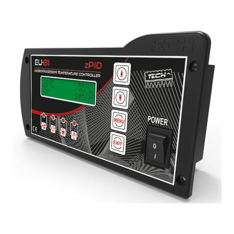
Tech Controllers
Tech Controllers EU-81zPID user manual
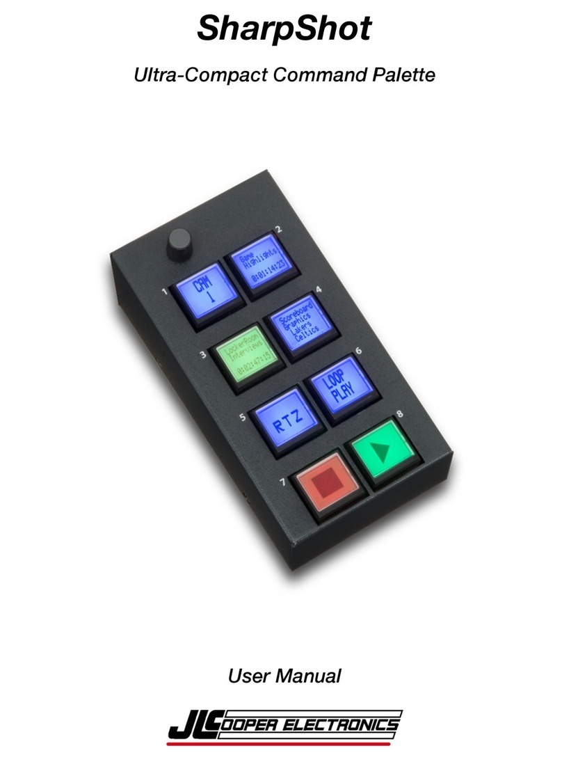
JLCooper Electronics
JLCooper Electronics SharpShot user manual
Truma
Truma DuoControl vertical operating instructions
Hunter
Hunter Eco-Logic 6 Owners manual and programming instructions
Autonics
Autonics TZN Series manual
Controlli
Controlli MVE2XX Mounting instructions
