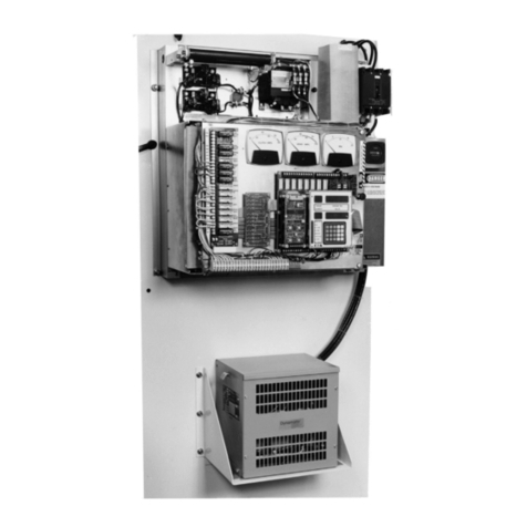
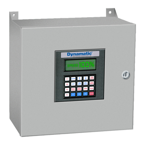
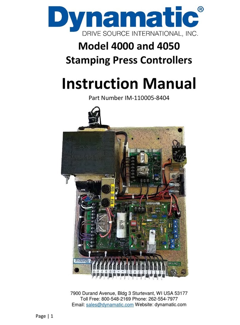
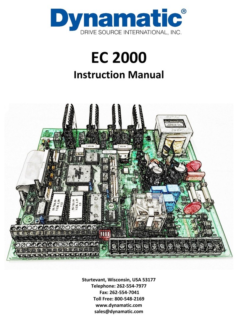
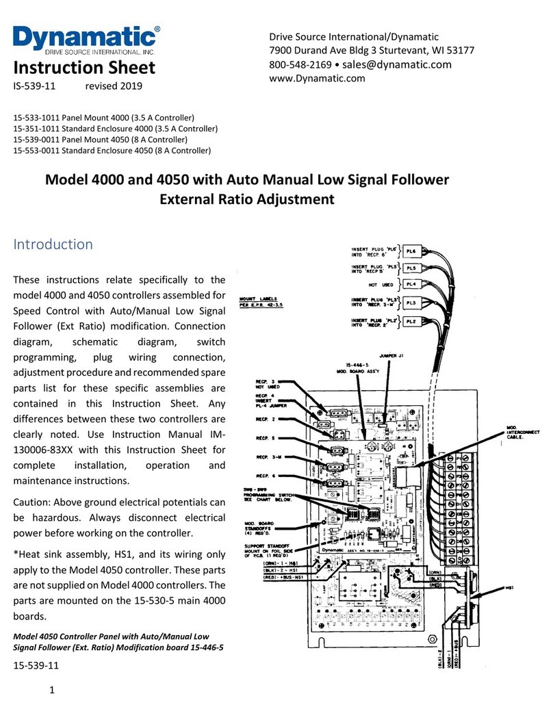
Dynamatic 4050 User manual

Page | 1
Model 4000 and 4050 Controllers
Instruction Manual
Part Number IM-130006-9801
7900 Durand Avenue, Bldg 3 Sturtevant, WI USA 53177
Toll Free: 800-548-2169 Phone: 262-554-7977
Email: sales@dynamatic.com Website: dynamatic.com

Page | 2
Table of Contents
Section 1........................................................................................................................................... 5
General Information .................................................................................................................... 5
Introduction ............................................................................................................................. 5
Safety ....................................................................................................................................... 5
Training .................................................................................................................................... 6
Receiving and Damage Claims ................................................................................................. 6
Warranty .................................................................................................................................. 6
Handling ................................................................................................................................... 6
Storage ..................................................................................................................................... 6
Long Term Storage ................................................................................................................... 7
Removal from Storage ............................................................................................................. 7
Numbering System................................................................................................................... 7
Symbols used in Illustrations .................................................................................................10
Section 2.........................................................................................................................................11
4000 and 4050 Controller Description....................................................................................... 11
Specifications .........................................................................................................................11
Basic Controller Assembly...................................................................................................... 12
Modification PCB’s................................................................................................................. 13
Packaging Options..................................................................................................................13
Table 2-1 Standard Enclosed Model 4000 Controller........................................................ 14
Table 2-2 Panel Mounted 4000 Controllers.......................................................................15
Table 2-3 Panel Mounted 4050 Controllers.......................................................................16
Table 2-4 NEMA 1 Enclosure 4050 Controllers.................................................................. 17
Section 3.........................................................................................................................................18
Assembly ....................................................................................................................................18
Identification..........................................................................................................................18
Main Printed Circuit Board Support.......................................................................................18
Modification PCB ...................................................................................................................19
Wiring..................................................................................................................................... 20
Section 4.........................................................................................................................................21
Installation ................................................................................................................................. 21
Location..................................................................................................................................21
Mounting Panel Mounted Model 4000 and 4050 Controllers .............................................. 21
Mounting an Input Transformer ............................................................................................ 22
Wiring..................................................................................................................................... 22

Page | 3
Programming Dip Switch .......................................................................................................23
Section 5.........................................................................................................................................25
Operation...................................................................................................................................25
Basic Controller Theory.......................................................................................................... 25
Linear Acceleration Option .................................................................................................... 26
Fixed Brake Option................................................................................................................. 27
Figure 5-2: Model 4000/4050 Controller Block Diagram................................................. 27
Spring Set Brake Option......................................................................................................... 28
Adjustable Brake Modification, 15-444-4 ..............................................................................28
Alternate Speed Modification, 15-444-3 ............................................................................... 28
Tach Follower Modification, 15-444-1................................................................................... 29
Low signal Follower Modification 15-446-1/5/101 ...............................................................29
Torque/Speed Modification, 15-444-5 ..................................................................................29
Torque Limit Modification, 15-444-2..................................................................................... 30
Dancer Position Modification, 15-444-7................................................................................ 30
Figure 5-3: Model 4000 Controller Schematic with 15-530-5 Main Assembly ................ 31
Figure 5-4: Model 4050 Controller Schematic with 15-530-6 Main PCB Assembly........... 32
Mutuatrol® Modification, 15-446-2....................................................................................... 33
Variable Air Volume Modification (VAV), 15-446-3/102 ....................................................... 33
Linear Accel/Decel Modification, 15-446-4 ...........................................................................33
Section 6.........................................................................................................................................34
Start-Up and Adjustments .........................................................................................................34
Tools Required .......................................................................................................................35
Power Off Tests......................................................................................................................35
Power on Tests....................................................................................................................... 36
Set-Up of Main PCB Assembly ...............................................................................................37
Basic Speed Control ............................................................................................................... 37
LED Set-Up ............................................................................................................................. 38
Zero Adjust R19 with LED monitor- ................................................................................... 38
Zero Adjust R19, Alternate Method- .................................................................................38
Max Speed/Volts R21.........................................................................................................39
Max Speed/Volts R21 with LED Monitor ........................................................................... 39
Max Speed/Volts R21, Alternate Methods-.......................................................................39
Time Constant (TC) Adjust R26-.........................................................................................40
Accel Rate R18 ...................................................................................................................40
Page | 4
Velocity Damping R22-....................................................................................................... 41
Current Feedback, R20- .....................................................................................................42
Basic Torque Control (Used when speed control is not used)............................................... 43
Section 7.........................................................................................................................................44
Maintenance and Trouble Shooting .......................................................................................... 44
Maintenance ..........................................................................................................................44
Trouble Shooting.................................................................................................................... 44
If the drive will not run: .....................................................................................................44
If the drive runs at full speed: ............................................................................................ 45
Renewal Parts and Service.....................................................................................................46

Page | 5
Section 1
General Information
Introduction
This instruction manual contains the necessary information required for normal installation, operation
and maintenance of the Model 4000 and 4050 Eddy Current Controllers. Please make it available to all
maintenance and operating personnel.
The Model 4000 and 4050 Eddy Current Controllers are high quality performance controllers capable of
operating Dynamatic Ajusto-Spede drives. The 4000 controller can be used with the Fractional Drives (.5
HP thru 1.5 HP), AS-14 thru AS-25 (.75 HP thru 20 HP) and the AT-140 thru AT-280 (1 HP thru 50 HP) The
4050 Controller can be used with the fractional Drives (.5 HP thru 1.5 HP), AS-14 thru AS-27 (.75 HP thru
40 HP), AT-140 thru AT-440 (1 HP thru 200 HP) and the AS-705 Air Cooled Brake
The Model 4000 and 4050 controllers are available in panel mount configurations designed for use in a
customer’s enclosure or they may be supplied in their own enclosure. Operator’s elements are provided
by Dynamatic at the customer’s request. Wiring of these elements is the customer’s responsibility.
The controllers’ flexible design allows them to be programmed by use of a Dip switch for wither speed
or torque control. They can be used with any combination of the basic controller and one of the
modifications, providing the interconnection is completed according to the schematic and connection
diagrams provided. Any combination of modifications or use of a modification not designed for the
controllers is not authorized.
Instructions provided in this manual are arranged in their normal order of use. Beginning with general
information, the instructions proceed from receiving, handling and storage, through installation, start-
up and adjustments to maintenance and trouble shooting. Written as a guide, these instructions do not
cover or describe each detail or modification in the controller. Use this instruction manual in conjunction
with any specific schematic, prints or instructions supplied with your controller. Certified drawings shall
take precedence over printed instruction material if a difference in content occurs.
While every effort has been made to provide a complete and accurate manual, there is no substitute for
trained, qualified personnel to handle unusual situations. If any questions arise regarding the operation
or maintenance of this controller, please refer them immediately to Dynamatic Customer Service at 262-
554-7977.
Safety
With any electronic or electrical rotating equipment, potential safety hazards are present and require
safeguards for proper use. This equipment must be installed properly, using safe procedures that meet
the requirements of all applicable safety codes. The wiring must be in accordance with the National
Electrical Code and all other local codes and regulations. Shaft guards, as well as protection for
operating and maintenance personnel against high voltage and moving machine parts, is essential. Refer
to OSHA rules and regulations, paragraph 1910.219, for guards on mechanical power transmission
apparatus. Pleases heed these safety instructions.

Page | 6
DANGER, WARNING, CAUTION and special INSTRUCTION labels are applied to the equipment to remind
you of the hazards the exist. Know your equipment before handling or working on it.
DANGER… is used where an immediate hazard exists. Failure to follow instructions could be fatal
WARING… means a possibility of injury to personnel, but not as severe as a Danger Warning.
CAUTION… is used to warn of potential hazards and unsafe practices.
INSTRUCTION… labels and notes are used when there is a need for special instructions related to safety,
proper operation or maintenance.
Training
Training programs are an essential part of safe and correct operation. Training provides the know-how
necessary to obtain top performance from your equipment. Dynamatic recognizes this fact and conducts
training schools to educate your plant personnel in safe maintenance and operating procedures. There is
a nominal charge for this service. Contact customer service at 262-554-7977 to set up a date.
Receiving and Damage Claims
The Model 4000 and 4050 controllers have been operated and tested at the factory prior to shipment.
Specific test procedures are followed to assure the quality of your controller. Carrier approved packing
methods assure safe shipment to your plant. Shipment is made F.O.B. from our factory, with the carrier
assuming responsibility for your unit. Therefore, it is essential that you carefully inspect the shipment
upon delivery to ensure that no damage or lost items have occurred in transit, Loss or damage is
covered by the carrier, not by the product warranty. File a claim immediately with the carrier if any
damage or loss is found. Should you require assistance in settling your claim with the carrier, contact
Dynamatic. You will need the unit model number, serial number and your purchase order number for
identification.
Warranty
Your new Model 4000 or 4050 controller is covered by a one-year warranty against any manufacturing
defect in either material or workmanship. Should the controller fail with in the one-year warranty
period, contact Dynamatic for a return material authorization (RMA) form. Fill in all required information
on the form and return the form with the controller to our Repair Service Department in Sturtevant,
Wisconsin for warranty repair or exchange. Your controller will either be repaired or replaced with a
preciously repaired exchange controller. Freight charges both ways are your responsibility.
Handling
Then Model 4000 and 4050 controllers weigh only a few pounds and can be hand carried safely. Do not
drop or subject the controller to shock or vibration. Do not stack heavy material on the controller. The
printed circuit boards and other components may be mounted on an open panel making the controller
very accessible to damage
Storage
Store the controller in a clean dry location with a non-corrosive atmosphere protected from sudden
temperature changes, high levels of moisture, shock and vibration. Electrical components are delicate
and easily damaged; provide adequate protection for them.

Page | 7
Ambient temperature should not exceed 25°C (77°F) on a continuous basis or 40°C (104°F) on an
intermittent basis. The minimum temperature must remain above freezing and the dew point of
ambient air. High temperature, corrosive atmosphere and moisture are detrimental to controller
equipment.
Long Term Storage
The manufacturer’s warranty covers repair or replacement of defective materials and rectification of
faulty workmanship. It does not cover damage and deterioration that transpire during the storage
period.
Some examples of deterioration due to storage are:
1. Corrosion of terminals and contacts
2. Breakdown of electrolytic capacitors
3. Moisture absorption within insulation and composition resistors.
These are not manufacturer’s defects and will not be covered by the warranty policy. Refer questions to
the Field Service Department in Sturtevant Wisconsin.
Removal from Storage
Before returning the controller to service after long time storage, it will be necessary to carefully inspect
it for any signs of damage or deterioration. Correct any deficiency. Carefully inspect the controller for
signs of moisture, especially with respect to transformers and composition resistors. If moist, the
transformer will require thorough drying. Damp resistors will change impedance and affect performance
of the controller; they should be replaced.
Corrosion is an important factor. Inspect terminals, plugs, sockets and contacts for signs of corrosion. If
detected, cleaning will be necessary.
Before applying power, make sure all connections are tight.
These procedures are given only as recommendations offered to aid our customers in preserving stored
equipment. We cannot guarantee stored equipment, even if all suggestions are followed; damage or
deterioration may still occur. Equipment storage is not covered by warranty.
Numbering System
The numbering system for electrical component and assembly part numbers contains some useful data
which could be of value to the technician working with or trouble shooting the controller. The number is
twelve digits, arranged in a two-six-four-digit sequence with the groups separated by dashes. As an
example, one printed circuit board part number is 15-000530-0006. This twelve-digit number is the
complete number as recognized by the computer. Frequently, the number is abbreviated by dropping
zeros, i.e.., 15-530-6. The number printed on the board and in the technical instruction material is the
abbreviated form. However, the actual bill of material and order paper work for the board would use
the complete number.

Page | 8
The first two digits of the part number identifies the parts category. As in the precious example, the 15
designates an assembly. The following table lists the complete category listing and assigned numbers
used as the first two digits of the part number.
Category Number and Descriptions
14
Alarms
35
Generators
56
Shock Mountings
15
Assemblies
36
Hardware
57
Solenoids
16
Bearings
37
Instruments
58
Switches
17
Blocks
38
Insulators and Insulations
59
Servo mechanisms
18
Blowers
39
Lights & Fixtures
60
Terminals
19
Brackets
40
Motors
61
Thermal devices (excluding
motor starter heaters)
20
Cables
41
Motor starters & Controls
62
Timers
21
Cams & Gears, cam Switch
assemblies
42
Nameplates
63
Transducers
22
Cans
43
Operating mechanism
(breakers)
64
Transformers, chokes
23
Capacitors
44
Operator panels
65
Tube sockets
24
Chassis
45
Panels
66
Valves
25
Circuit Breakers
46
Phase Shifters
67
Wires
26
Coils & Coil Assemblies
47
Photoelectrical
68
Wiring Ducts
27
Connectors, plugs, sockets
48
Plates
69
Tubes
28
Control units & parts
49
Potentiometers
70
Insulated Mounting Boards
29
Counters
50
Power Converters
71
30
Dial plates & knobs
51
Reactors
72
Master bills of material
31
Enclosures
52
Regulators
73
Engineering Data Sheets
32
Fuses & Fuses Holders
53
Relays & Contactors
74
33
Filters (radio interference)
54
Resistors
75
Reworked Assemblies
34
Gaskets & Gasket
Materials
55
Semi-conductors
The middle six digits describe a basic type of part, such as physical or electrical characteristics of a group
or family of parts. As an example, a resistor family of ½ watt carbon resistors has the number 000045.
The part number of on specific resistor in this family is 54-000045-0102.
Category
Part Name
Parameter Described
23
Capacitor
Capacitance
32
Fuses
Ampere Rating
49
Potentiometer
Resistance
54
Resistors
Resistance
55
Power diodes & SCR’s
Peak Reverse Voltage

Page | 9
The last four digits describe a specific part within the family and may be assigned in numerical sequence
or may describe the specific part value. The following table lists those part categories where the last
four digits have a significant meaning to the technician.
Last 4 Digits
Numeric Value
2593
.025
2592
.25
2591
2.5
0250
25
0251
250
0252
2500
0253
25000

Page | 10
Symbols used in Illustrations

Page | 11
Section 2
4000 and 4050 Controller Description
The Model 4000 and 4050 controllers are available as a panel mount or in an enclosure. They are solid
state eddy-current controllers employing an integrated circuit design with a transistorized out-put. The
4050 is designed to provide a higher current output, 8 amps at 45 volts, so it can be used on AC drives
up through 200 HP. The output of the 4000 controller is 0 to 45 Vdc rated at 0 to 4.3 amps and can be
used on drives up to 20 HP. Descriptions of other features available on these controllers follow. The
adjustable time constant circuit matches the controller to the time constant of the mechanical unit. An
LED Set-up Indicator circuit enables the maximum speed and minimum bias to be set visually by means
of an “onboard” light emitting diode, in most cases eliminating the need for a meter. Because the
requirements for damping increase with higher horsepower drives and higher inertia, the velocity
damping ranges on the Model 4000 and 4050 controllers have been extended to approximately twice
that of the original Model 4000 controller. Current feedback damping is available for customers who
require this type of response. The output of each controller is short circuit proof, which includes the
following conditions:
1. Shorting of terminal C1 to C2
2. Shorting of terminal B1 to B2
3. Shorting of terminals C1 or C2 to earth ground
4. Shorting of terminals B1 or B2 to earth ground
If any of these events occur, the controller shall be completely self-protecting without damage to any of
its internal components. Input power for the controller is supplied from a 115 Vac transformer winding
in the drive’s ac motor. A separately mounted 115 Vac transformer is Also available if required.
Pushbutton operation by a Run relay is standard; also, the Run relay has an extra set of NO (Normally
Open) contacts available for customer’s use.
Numerous safety features protect the Model 4000 and 4050 controllers and associated equipment from
possible damage due to drive overloads, loss of power, transients and other electrical or mechanical
failures. All trim potentiometers are sealed.
Specifications
Input Voltage
115 Vac, CT. +20%, -10%, 50/60 Hz
Input Current
Model 4000
4 Aac rms
Model 4050
7 Aac rms
Output Voltage
45 Vdc nominal at either terminals C1 or C2
(clutch) or B1 and B2 (brake)
Output Current
Model 4000
4.3 Adc continuous
Model 4050
8 Adc continuous
Extra Run Relay Contact (NO)
115 Vac, or 24 Vdc, 5A resistive, 150 V. pilot duty

Page | 12
Load Regulation
-0.5% of maximum rated speed for no load to
100% load change
Line Regulation
±0.1% of rated speed for ±10% input line voltage
change
Thermal Drift
±0.05% of rated speed per degree C. (or ±0.03%
per degree F.)
Linearity
±2% of maximum rate speed, reference voltage
to speed
Min Regulated Speed
50 rpm
Zero Adjust Range
0 to 15% of rated speed
Linear Accel Range
3 to 80 seconds
Fuses FU1, FU2
Model 4000
4 A, 250 Vac
Model 4050
10 A, 250 Vac
Ambient
0°- 40°C. (32°- 104°F.) Cast enclosure Model 4000
only
0°- 65° (32° - 148° F.) Panel mount Model 4050
Mounting
Model 4000
NEMA 13 or open panel
Model 4050
NEMA 13 or open panel
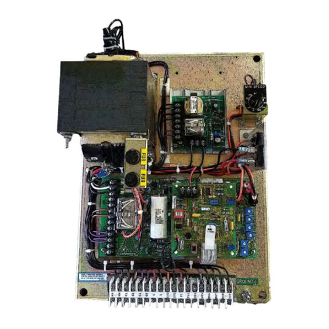
Basic Controller Assembly
The main PCB (15-530-5/6) is mounted to the panel by four standoffs. A support standoff is located in
the middle of the board (foil side). See Figure 3-1 for proper insertion of this standoff. A ground stud is
provided for grounding the enclosure/panel to an existing enclosure. A 13-position terminal block across
one end of the main PCB is provided for connections to the mechanical unit. Near the center, along one
side of the board, is a 16-pin receptacle (RECP1) into which is plugged a 4 pole, 8 pin Dip switch. This Dip
switch is removed and replaced with a 16-pin plug and mod interconnect ribbon cable when a
modification PCB is used. Three additional options are built into each main PCB assembly: Linear
Acceleration, Fixed Brake and basic Torque Control. The customer may elect to use one or more of these
optional features. The Dip switch on the main PCB connects the acceleration circuit. Terminals B1 & B2
are provided for the brake option; a set of NO contacts is wired to terminals D7 and D8 for customer
use. This set of contacts is normally open when the controller Run relay is deenergized and can be used
to operate a spring set brake.
The Model 4000 and 4050 controllers are available for customer mounting within an existing enclosure,
however they are also available in their own enclosure when specified.
The customer is required to wire his own operator’s elements to the panel mount version of the
controller.
When the controller is to be used with a modification PCB, the instruction sheet provided with the board
contains the mounting instructions for the modification board, plug wiring information, schematic
diagram, and the connection diagram for the complete controller.

Page | 13
Modification PCB’s
Modification printed circuit boards for these controllers are 3.5” by 3.9” or 4.5” by 3.9”. Any one
modification board may be used with the main PCB as required. The following list includes the twelve
basic types of modification boards available with the Model 4000 and 4050 controllers. Tables 2-1
through 2-5 list the 21 to 23 different types of controllers available for each.
Description
Part Number
Tachometer Follower PCB
15-444-1
Torque Limit PCB
15-444-2
Alternate Speed PCB
15-444-3
Adjustable Brake PCB
15-444-4
Torque/Speed PCB
15-444-5
Dancer Position PCB
15-444-7
Instrument Sig. Follower PCB
15-446-1/5
Mutuatrol PCB (used only with drives thru 20 HP)
15-446-2
Variable Air Volume PCB
15-446-3/102
Linear Accel/Decel PCB
15-446-4
Packaging Options
The Model 4000 and 4050 controllers are available in the following packaging options:
The Standard Enclosed 4000 Controllers: (assembly numbers 15-551-10**) are complete controllers
with the operator’s elements located in the cover of the NEMA 13 enclosure.
The Panel Mount 4000 Controllers: (assembly numbers 15-533-10**) are intended to be mounted in
the customer’s enclosure. A remote operator’s station is required for this controller version.
The Panel Mount 4050 Controllers: (assembly numbers 15-539-00**) are intended to be counted in the
customer’s enclosure. A remote operator’s station is required for this controller version.
The Standard Enclosed 4050 Controllers: (assembly numbers 15-553-00**) are complete controllers
mounted in a NEMA 13 enclosure. A remote operator’s station is required for this controller version.
** Model number, 01 through 26.

Page | 14
Table 2-1 Standard Enclosed Model 4000 Controller
Model 4000
Controller Type
Final
Assembly
Mod.
Board
Pos 1.
Pos. 2.
Pos. 3
Pos. 4
Pos. 5
Options
Basic Speed Control
15-551-1001
Stop
Start
Run
Speed
Fixed Brake
Linear Accel
Speed w Adj Brake
15-551-1002
15-44-4
Stop
Start
Run
Speed
Linear Accel
Speed w Jog @ Run
Speed
15-551-1003
Stop
Start
Jog/Run
Run
Speed
Fixed Brake
Linear Accel
Speed w/ Adj. Brake &
Jog @ Run Speed
15-551-1004
15-444-4
Stop
Start
Jog/Run
Run
Speed
Linear Accel
Speed w/ Adj Jog
15-551-1005
15-444-3
Stop
Start
Jog/Run
Run
Speed
Fixed Brake
Linear Accel
Speed w/ Threading Int.
15-551-1006
15-444-3
Stop
Start
Thread/R
un
Run
Speed
Fixed Brake
Linear Accel
Speed w/ Threading Ext.
15-551-1007
15-444-3
Stop
Start
Thread/R
un
Run
Speed
Thread
Speed
Fixed Brake
Linear Accel
Speed w Cascade
(Auto/Manual)
15-551-1008
15-444-3
Stop
Start
Auto/
Manual
Man.
Speed
Ratio
Fixed Brake
Linear Accel
Speed w/ Tach Follower
(Auto/Man)
15-551-1009
15-444-1
Stop
Start
Auto/
Manual
Man.
Speed
Ratio
Fixed Brake
Linear Accel
Speed w/ Low Signal
Follower Int. Ratio
(Auto/Man)
15-551-1010
15-446-1/5
Stop
Start
Auto/
Manual
Man.
Speed
Fixed Brake
Linear Accel
Speed w/ Low Signal
Follower Ext Ratio
(Auto/Man)
15-551-1011
15-446-1/5
Stop
Start
Auto/
Manual
Man.
Speed
Ratio
Fixed Brake
Linear Accel
Torque Control
15-551-1012
Stop
Start
Run
Speed
Fixed Brake
Speed/Torque
15-551-1013
15-444-5
Stop
Start
Thread/R
un
Run
Speed
Torque
Fixed Brake
Linear Accel
Speed w/ Torque Limit
15-551-1014
15-444-2
Stop
Start
Run
Speed
Fixed Brake
Linear Accel
Speed w Torque Limit &
Jog @ Run Speed
15-551-1015
15-444-2
Stop
Start
Dancer
Pos
Fixed Brake
Linear Accel
Mutuatrol
15-551-1017
15-446-2
Stop
Start
Run
Speed
Linear Accel
Mutuatrol w Jog @ Run
Speed
15-551-1018
15-446-2
Stop
Start
Jog/Run
Run
Speed
Linear Accel
Speed w/ Variable Air
Volume (Auto/Manual
w/o Run Stop
15-551-1023
15-446-
3/102
Stop
Start
Auto/
Manual
Man.
Speed
Fixed Brake
Speed w/ Variable Air
Volume (Auto/Manual w
Run Stop
15-551-1024
15-446-
3/102
Stop
Start
Auto/
Manual
Man.
Speed
Fixed Brake
Speed w Linear
Accel/Decel
15-551-1025
15-446-4
Stop
Start
Run
Speed
Fixed Brake
Speed w Linear
Accel/Decel & Adjustable
Jog
15-551-1026
15-446-4
Stop
Start
Jog/Run
Run
Speed
Fixed Brake

Page | 15
Table 2-2 Panel Mounted 4000 Controllers
Model 4000
Controller Type
Final
Assembly
Mod.
Board
Pos 1.
Pos. 2.
Pos. 3
Pos. 4
Pos. 5
Options
Basic Speed Control
15-533-1001
Stop
Start
Run
Speed
Fixed Brake
Linear Accel
Speed w Adj Brake
15-533-1002
15-44-4
Stop
Start
Run
Speed
Linear Accel
Speed w Jog @ Run
Speed
15-533-1003
Stop
Start
Jog/Run
Run
Speed
Fixed Brake
Linear Accel
Speed w/ Adj. Brake &
Jog @ Run Speed
15-533-1004
15-444-4
Stop
Start
Jog/Run
Run
Speed
Linear Accel
Speed w/ Adj Jog
15-533-1005
15-444-3
Stop
Start
Jog/Run
Run
Speed
Fixed Brake
Linear Accel
Speed w/ Threading Int.
15-533-1006
15-444-3
Stop
Start
Thread/R
un
Run
Speed
Fixed Brake
Linear Accel
Speed w/ Threading Ext.
15-533-1007
15-444-3
Stop
Start
Thread/R
un
Run
Speed
Thread
Speed
Fixed Brake
Linear Accel
Speed w Cascade
(Auto/Manual)
15-533-1008
15-444-3
Stop
Start
Auto/
Manual
Man.
Speed
Ratio
Fixed Brake
Linear Accel
Speed w/ Tach Follower
(Auto/Man)
15-533-1009
15-444-1
Stop
Start
Auto/
Manual
Man.
Speed
Ratio
Fixed Brake
Linear Accel
Speed w/ Low Signal
Follower Int. Ratio
(Auto/Man)
15-533-1010
15-446-1/5
Stop
Start
Auto/
Manual
Man.
Speed
Fixed Brake
Linear Accel
Speed w/ Low Signal
Follower Ext Ratio
(Auto/Man)
15-533-1001
15-446-1/5
Stop
Start
Auto/
Manual
Man.
Speed
Ratio
Fixed Brake
Linear Accel
Torque Control
15-533-1012
Stop
Start
Run
Speed
Fixed Brake
Speed/Torque
15-533-1013
15-444-5
Stop
Start
Torque/S
peed
Run
Speed
Torque
Fixed Brake
Linear Accel
Speed w/ Torque Limit
15-533-1014
15-444-2
Stop
Start
Run
Speed
Fixed Brake
Linear Accel
Speed w Torque Limit &
Jog @ Run Speed
15-533-1015
15-444-2
Stop
Start
Jog/Run
Dancer
Pos
Fixed Brake
Linear Accel
Dancer Position
15-533-1016
15-444-7
Mutuatrol
15-533-1017
15-446-2
Stop
Start
Run
Speed
Linear Accel
Mutuatrol w Jog @ Run
Speed
15-533-1018
15-446-2
Stop
Start
Jog/Run
Run
Speed
Linear Accel
Speed w/ Torque Limit
Shock Mount
15-533-1019
See IM-
11005-8300
Speed w Torque Limit w
Minimum Speed Pot
15-533-1020
See IM-
11005-8300
Speed w/ Variable Air
Volume (Auto/Manual)
15-533-1021
15-446-
3/102
Stop
Start
Auto/
Manual
Man.
Speed
Fixed Brake
Speed w Linear
Accel/Decel
15-533-1025
15-446-4
Stop
Start
Run
Speed
Fixed Brake
Speed w Linear
Accel/Decel & Adjustable
Jog
15-533-1025
15-446-4
Stop
Start
Jog/Run
Run
Speed
Fixed Brake

Page | 16
Table 2-3 Panel Mounted 4050 Controllers
Model 4050
Controller Type
Final
Assembly
Mod.
Board
Pos 1.
Pos. 2.
Pos. 3
Pos. 4
Pos. 5
Options
Basic Speed Control
15-539-0001
Stop
Start
Run
Speed
Fixed Brake
Linear Accel
Speed w Adj Brake
15-539-0002
15-44-4
Stop
Start
Run
Speed
Linear Accel
Speed w Jog @ Run
Speed
15-539-0003
Stop
Start
Jog/Run
Run
Speed
Fixed Brake
Linear Accel
Speed w/ Adj. Brake &
Jog @ Run Speed
15-539-0004
15-444-4
Stop
Start
Jog/Run
Run
Speed
Linear Accel
Speed w/ Adj Jog
15-539-0005
15-444-3
Stop
Start
Jog/Run
Run
Speed
Fixed Brake
Linear Accel
Speed w/ Threading Int.
15-539-0006
15-444-3
Stop
Start
Thread/R
un
Run
Speed
Fixed Brake
Linear Accel
Speed w/ Threading Ext.
15-539-0007
15-444-3
Stop
Start
Thread/R
un
Run
Speed
Thread
Speed
Fixed Brake
Linear Accel
Speed w Cascade
(Auto/Manual)
15-539-0008
15-444-3
Stop
Start
Auto/
Manual
Man.
Speed
Ratio
Fixed Brake
Linear Accel
Speed w/ Tach Follower
(Auto/Man)
15-539-0009
15-444-1
Stop
Start
Auto/
Manual
Man.
Speed
Ratio
Fixed Brake
Linear Accel
Speed w/ Low Signal
Follower Int. Ratio
(Auto/Man)
15-539-0010
15-446-1/5
Stop
Start
Auto/
Manual
Man.
Speed
Fixed Brake
Linear Accel
Speed w/ Low Signal
Follower Ext Ratio
(Auto/Man)
15-539-0011
15-446-1/5
Stop
Start
Auto/
Manual
Man.
Speed
Ratio
Fixed Brake
Linear Accel
Torque Control
15-539-0012
Stop
Start
Torque
Fixed Brake
Speed/Torque
15-539-0013
15-444-5
Stop
Start
Torque/S
peed
Run
Speed
Torque
Fixed Brake
Linear Accel
Speed w/ Torque Limit
15-539-0014
15-444-2
Stop
Start
Run
Speed
Fixed Brake
Linear Accel
Speed w Torque Limit &
Jog @ Run Speed
15-539-0015
15-444-2
Stop
Start
Jog/Run
Run
Speed
Fixed Brake
Linear Accel
Dancer Position
15-539-0016
15-444-7
Stop
Start
Dancer
Pos
Fixed Brake
Linear Accel
Mutuatrol
15-539-0017
15-446-2
Stop
Start
Run
Speed
Linear Accel
Mutuatrol w Jog @ Run
Speed
15-539-0018
15-446-2
Stop
Start
Jog/Run
Run
Speed
Linear Accel
Speed w/ Torque Limit
Shock Mount
15-539-0019
See IM-
11005-8300
Speed w Torque Limit w
Minimum Speed Pot
15-539-0020
See IM-
11005-8300
Speed w Linear
Accel/Decel
15-539-0025
15-446-4
Stop
Start
Run
Speed
Fixed Brake
Speed w Linear
Accel/Decel & Adjustable
Jog
15-539-0025
15-446-4
Stop
Start
Jog/Run
Run
Speed
Fixed Brake

Page | 17
Table 2-4 NEMA 13 Enclosure 4050 Controllers
Model 4050
Controller Type
Final
Assembly
Mod.
Board
Pos 1.
Pos. 2.
Pos. 3
Pos. 4
Pos. 5
Options
Basic Speed Control
15-553-0001
Stop
Start
Run
Speed
Fixed Brake
Linear Accel
Speed w Adj Brake
15-553-0002
15-44-4
Stop
Start
Run
Speed
Linear Accel
Speed w Jog @ Run
Speed
15-553-0003
Stop
Start
Jog/Run
Run
Speed
Fixed Brake
Linear Accel
Speed w/ Adj. Brake &
Jog @ Run Speed
15-553-0004
15-444-4
Stop
Start
Jog/Run
Run
Speed
Linear Accel
Speed w/ Adj Jog
15-553-0005
15-444-3
Stop
Start
Jog/Run
Run
Speed
Fixed Brake
Linear Accel
Speed w/ Threading Int.
15-553-0006
15-444-3
Stop
Start
Thread/R
un
Run
Speed
Fixed Brake
Linear Accel
Speed w/ Threading Ext.
15-553-0007
15-444-3
Stop
Start
Thread/R
un
Run
Speed
Thread
Speed
Fixed Brake
Linear Accel
Speed w Cascade
(Auto/Manual)
15-553-0008
15-444-3
Stop
Start
Auto/
Manual
Man.
Speed
Ratio
Fixed Brake
Linear Accel
Speed w/ Tach Follower
(Auto/Man)
15-553-0009
15-444-1
Stop
Start
Auto/
Manual
Man.
Speed
Ratio
Fixed Brake
Linear Accel
Speed w/ Low Signal
Follower Int. Ratio
(Auto/Man)
15-553-0010
15-446-1/5
Stop
Start
Auto/
Manual
Man.
Speed
Fixed Brake
Linear Accel
Speed w/ Low Signal
Follower Ext Ratio
(Auto/Man)
15-553-0011
15-446-1/5
Stop
Start
Auto/
Manual
Man.
Speed
Ratio
Fixed Brake
Linear Accel
Torque Control
15-553-0012
Stop
Start
Torque
Fixed Brake
Speed/Torque
15-553-0013
15-444-5
Stop
Start
Torque/S
peed
Run
Speed
Torque
Fixed Brake
Linear Accel
Speed w/ Torque Limit
15-553-0014
15-444-2
Stop
Start
Run
Speed
Fixed Brake
Linear Accel
Speed w Torque Limit &
Jog @ Run Speed
15-553-0015
15-444-2
Stop
Start
Jog/Run
Run
Speed
Fixed Brake
Linear Accel
Dancer Position
15-553-0016
15-444-7
Stop
Start
Dancer
Pos
Fixed Brake
Linear Accel
Mutuatrol
15-533-0017
15-446-2
Stop
Start
Run
Speed
Linear Accel
Mutuatrol w Jog @ Run
Speed
15-533-0018
15-446-2
Stop
Start
Jog/Run
Run
Speed
Linear Accel
Speed with Variable Air
Volume (Auto/Manual)
15-533-0021
15-446-
3/102
Stop
Start
Auto/
Manual
Man.
Speed
Fixed Brake
Speed w Linear
Accel/Decel
15-533-0025
15-446-4
Stop
Start
Run
Speed
Fixed Brake
Speed w Linear
Accel/Decel & Adjustable
Jog
15-533-0025
15-446-4
Stop
Start
Jog/Run
Run
Speed
Fixed Brake

Page | 18
Section 3
Assembly
This section describes the procedure for assembling the basic Model 4000 and 4050 controllers or
modifying an existing controller with one of the 12 available modification boards that make up the 4000
and 4050 system. If you have purchased a complete controller, this section can be passed over and you
may proceed with the next section, covering installation.
Identification
Before beginning to assemble or change your Model 4000 or 4050 controller, identify the type of final
assembly you need. All standard options to your controller are listed in Section 2, Tables 2-1 through 2-
4. These tables describe each modification, give the final assembly number and list the part numbers of
sub-assemblies required to make the modification. Refer to the Instruction Sheet included with the
modification PCB and this basic instruction manual for the necessary wiring instructions. The Instruction
Sheet will carry the final assembly part number of your controller.
Main Printed Circuit Board Support
When mounting the main PCB to your controller panel or enclosure, it will be necessary to insert a
center support standoff on the main board to add stability. The following instructions are provided to
help you this task. Insert a support standoff into the hole on the back side (foil side) of the board as
shown in Figure 3-1. Position tabs between soldered leads so the standoff may be seated properly to
allow the locking tips to lock. Then mount the printed circuit board to the panel with the four mounting
screws that are furnished.
Caution: Do not push on components when inserting standoff or damage may result.
Figure 3-1 15-263-14 Support Standoff Kit
Insert support standoff into
hole on back side (foil side) of
board as shown. Position tabs
between soldered leads so that
standoff may be seated
properly to allow locking tips
to lock.
Caution: Do not push parts on
component side when inserting
standoff or damage may result

Page | 19
Modification PCB
When a modification PCB assembly is required, we suggest you install this board according to the
following procedure:
1. Place the main PCB in front of you with the long dimension in a horizontal position and the
terminal strip to the left.
2. Locate the dual in-line, 4 position Dip switch plugged into receptacle RECP 1 on the main PCB
assembly. RECP 1 is 2.5” from the right edge and 1.0” from the bottom edge of the board.
3. Remove the Dip switch by pulling it straight out of the receptacle. Save the switch for some
future use. Then, peel the adhesive-backed label off the other half of RECP 1.
4. Four nylon standoffs are supplied with each modification PCB assembly. Locate the four 0.188”
diameter holes in the main PCB assembly. Refer to your assembly illustration for the location of
these holes. Insert the arrow type locking head of a standoff into each of the holes in the main
PCB assembly and press them in. The tabs will snap out to lock the standoffs permanently in
position. Replacement standoffs are available by ordering the standoff kit assembly, 15-263-16,
which contains four standoffs
Figure 3-2: Modification PCB Standoff
5. Hold the modification PCB assembly
over the standoffs with the ribbon connector
toward you, which should be over RECP 1
receptacle. Insert the ribbon Connector plug
into RECP 1. Be careful to see that all 16 pins
are started properly into the receptacle before
pressing the plug in. These pins are easily bent.
To remove this connector, pull straight up on
the body of the plug. Do not pull on the ribbon
itself.
6. Align the holes in the modification PCB assembly over the standoffs and press over the tapered
posts until the locking flanges snap out to lock the board in position. To remove the board,
squeeze the locking flanges in with your fingers and lift off the board.

Page | 20
Wiring
In the standard NEMA 13 version, with the operator’s control elements mounted in the door, the
operator’s elements are completely wired. Wiring of the operator’s elements to the panel mount
version of the controller is through a 12-position terminal block, located on the right side of the panel.
All connections to this terminal block must be wired as shown on the connection diagram. The terminal
block is supplied with a marking strip identifying each terminal, P1 through D10. The inner side of the
terminal block is supplied with a prewired harness, complete with plugs of different sizes and
configurations, to aid in wiring your controller. These plugs are clearly identified by wire markers (PL2,
PL3, etc.) and are to be inserted in the main PCB or modification board’s matching receptacles (RECP 2,
RECP 3, etc.) Plugs supplied with the harness will allow you to modify your controller into any one of the
available types. Any plug(s) that you are not instructed to use for your specific controller should be
taped to the panel and out of the way. The plugs include spring latches at opposite sides that fit inside
molded catches in the receptacle body.
Align and insert them into the receptacle. Note the
groove(s) in one side of the plug and raided key(s) on
the receptacle to ensure proper alignment. For
modified controllers refer to the specific instruction
sheet for your controller for complete plug wiring
information.
Figure 3-3 Wiring Harness Plug & Receptacle
Other manuals for 4050
2
This manual suits for next models
1
Table of contents
Other Dynamatic Controllers manuals

Dynamatic
Dynamatic 4000 User manual

Dynamatic
Dynamatic 4050 User manual

Dynamatic
Dynamatic 4000 User manual

Dynamatic
Dynamatic 4050 User manual

Dynamatic
Dynamatic CES User manual

Dynamatic
Dynamatic 4000 User manual

Dynamatic
Dynamatic EC 2000-CES User manual

Dynamatic
Dynamatic EC 2000 User manual

Dynamatic
Dynamatic 4000 User manual