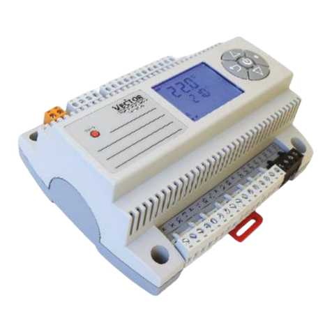
VECTOR CONTROLS T-EF Series User manual

T-EF-SERIES
DIGITAL ROOM CONTROLLER
Version: 2002-02 Page 1/ 4
T-EF Series Digital Room Controller
Summary
This controller enables the user to increase
the comfort level and save energy by
providing automatic control of indoor supply
air. The unit uses a digital display to indicate
room and set point temperature.
The user has additionally the option to
control the supply air independent of
temperature. The unit is operated with the
use of comfortable soft buttons. Its modern
design fits into contemporary and classic
interior designs of apartments, hotels and
offices alike.
The operation mode is a P control and it is
designed to control three point floating air
damper actuators.
Features & Benefits
qModern Design Blends in with modern decoration
qDigital Display Clear and accurate temperature indication or manual
positioning information
qAutomatic Air Control Increases comfort level and saves energy
qDual-color LED status Status of the unit at a glance
qManual Override Easy selection for special conditions, for example
Morning boost to exchange stale air, minimum air
supply while away, etc.
qMemory for settings All the settings are memorized. No reprogramming in
case of power failure or switch off.
qUniversal Mounting Can be mounted on British, American and Chinese
standard wall boxes
qClip on installation Time saving, simple and save installation costs
qCalibration Fine tuning of the VAV loop without opening of duct
qAuto Reset Accurate damper position even for floating control
Operation
The controller is used to control the position of
the supply air zone damper of a pressure
dependent VAV system.
1. Switching ON
The unit is switched on by pressing the
POWER button while in OFF mode.
2. Automatic Temperature Control
This mode will control the supply air damper
using a P control function. Press the
MANUAL/AUTO button once to activate temperature control mode if in manual mode.
The two-digit display indicates the current room temperature. The upper status LED
light up either green if cooling or red if heating mode is active. The temperature set
MANUAL/ AUTO
UP / Increase
HEAT/COOL
POWER
DOWN / Decrease
Mode selector

T-EF-SERIES
DIGITAL ROOM CONTROLLER
Version: 2002-02 Page 2/ 4
point is indicated by pressing the UP or DOWN key once. The set point will be changed,
if either one of this keys is pressed again within 2 seconds. The two-digit display will
return to indicate the room temperature after 2 seconds if no key is pressed.
3. Manual Control
The air volume can be manually adjusted by pressing
the MANUAL/AUTO button once while in auto mode.
The lower status LED will light up green. The two-
digit display will show the degree of the opening of
the damper from 0 -90°. The damper can be
positioned with 5° steps by pressing UP or DOWN
buttons.
4. Switching OFF
The unit is switched off by pressing the POWER
button once.
5. Changing HEATING/COOLING mode.
Pressing the HEAT/COOL button for more than 3 seconds will change the temperature
control mode. The mode of the unit is indicated by the color of the upper status LED.
Green is for cooling and red is for heating.
6. Calibration of P-Band
Warning! Calibration should only be done by experts!
The T-EF offers calibration of the P-band and the running time of the actuator.
Pressing MANUAL/AUTO and HEAT/COOL button together for two seconds starts the
calibration mode. The first step is the setting of the P-Band. Range is 2 -5 ° C. The
setting can be changed by pressing UP or DOWN button. The unit will return to normal
mode, if no key is pressed for two seconds.
7. Calibration of actuator timing
Warning! Calibration should only be done by experts!
Pressing MANUAL/AUTO and HEAT/COOL button together again while in calibration
mode will lead to the setting of actuator timing. The two-digit display indicates the
running time of the actuator in steps of 10 seconds. A display of 15 therefore stands for
150 seconds. Use UP or DOWN key to change the timing. The calibration can as well be
used to fine-tune the outlets in a VAV system. The opening of the damper can be limited
in areas of high pressure by reducing the running time setting of the actuator. Again,
this should only be done by experienced personnel. The unit will reset itself after a
change of actuator timing. The green and red LED will blink alternately and the damper
will be closed.
8. External Temperature Sensor
It is possible to connect an external sensor on the connectors 6 and 7. In order to use
the external connection, the internal sensor has to be removed. This is done by cutting
the legs of the sensor on the PCB. The sensor is marked RT. Use a standard NTC
temperature sensor for the external sensor.
9. Resetting
In order to keep the actuator position accurate at longer operation intervals, the unit is
reset each time the damper is closed. This is done automatically by extending the close
signal by 10s.
10.Power Failure
In case of a power failure the unit will close the damper at the resumption of power.
The status LED's will blink alternating red and green. The closing time depends on the
setting of the controller. (See point 7). The unit will remain in the OFF position after
closing. When switching on, the last recorded operation mode will be activated. All the
settings and set points are memorized and will not have to be re-entered.
Display
Two digital LED
number displays
indicate room -and
setpoint temperature.
The upper LED on the right side of
the display indicates heating (red) or
cooling (green) mode. The lower LED
shows manual operation (green)
88

T-EF-SERIES
DIGITAL ROOM CONTROLLER
Version: 2002-02 Page 3/ 4
Location and Dimensions
•On an easy accessible interior wall,
approx.
1.5 m above the floor in an area of
average temperature, but within
the distance of 5 m to the fan coil
outlet.
•Avoid direct sunlight or other heat
sources, e.g. the area above
radiators and heat emitting
electrical equipment.
•Avoid locations behind doors,
outside walls and below or above
air discharge grills and diffusers.
Installation
1. Install the mounting plate on the wall box. The type of screws required depends on the
wall box. For Chinese standard M4x25 screws are most suitable. The mounting plate
provides holes for most international standards. Horizontal distance of mounting screws
ranges from 35 to 65 mm; vertical distances are 58 to 85 mm.
2. On the upper side of the controller, there are two clips. Press them inside using a small
screwdriver.
3. Separate the front plate of the controller with the base by opening it carefully. Unplug
the connector from the button.
4. Connect the wirings as shown in the diagram below. Pay attention to follow local
guidelines regarding insulation and wire sizes.
5. Connect the main body to the mounting plate by holding it in place and inserting the
two small screws
that are part of
the package in
the upper left and
lower right
corner.
6. Reconnect the
plug of the button
and press the
front plate into
place. Insert the
lower part first
and then press
down the upper
part until hearing
a click

T-EF-SERIES
DIGITAL ROOM CONTROLLER
Version: 2002-02 Page 4/ 4
Wiring Diagram
Technical Specification
Power Supply 21.5 -26.5 V AC 50/60 Hz
Power Consumption 3 W
Electrical Connection Terminal Connectors
Output Current Max. 1 A
Timing range of actuator 30 -200 s
Control Temperature Range 10 to 35 °C
Temperature Accuracy ±0.2°C
Display precision 1.0°C
Temperature Sensor NTC (10..40°C)
or External
P-Band 2 -5 °C
Memorized settings Mode: Manual, Temperature Control
Heating Cooling
Set point:Temperature and Manual Position
Calibration: Timing and P-Band
Ambient Temperature -10 to 50°C
Ambient Humidity 0 to 95% rH Non Condensing
Degree of Protection IP30
Housing ABS plastic
Servicing Maintenance Free
Dimensions 110 x 90 x 35 mm (H x W x D)
Weight 130 g
Vector Controls Ltd.
Room 412, Building 7,
Xiao Yun Li, Xiao Yun Road,
Chao Yang District, Beijing,
100016, PRC
Tel: +86 10 6468 2382
Fax: +86 10 6468 2387
Email: [email protected]
T-EF
123
4
5
67
Actuator 24 VAC
1
2
3
⊥
∼
∼
⊥
∼
⊥
P
Q
Power Supply
AC 24V
⊥
∼
External NTC Type
temperature sensor
(optional)
Ground
Close
Open
RT
24 VAC
S
S
Sw
w
wi
i
is
s
ss
s
s
T
T
Te
e
ec
c
ch
h
h
-
-
-
n
n
no
o
ol
l
lo
o
og
g
gy
y
y
Other VECTOR CONTROLS Controllers manuals