Actwell Technology ACT-202Tx User manual

\~
"', ..
Fe CEO681<D1
..
Edition
First edition, September 2004
Copyright information
This publication, including all photographs, illustrations and software, is
protected under international copyright laws,with all rights reserved. Neither this
manual, nor any of the material contained herein, may be reproduced without
written consent of the author. .
-\\,
',~ @ September, 2004
'-< .
Trademarks
All product names used in this manual are the properties of their respective
owners and are acknowledged.
'"
'. ;~

FROM: ACTWELLTECHNOLOGYINC. FARNO. : 00886 2 22787363 SEP.17200403:OOPMP.I2
Safety and battery use
.Readandfollow any warningsin this manual.
.Readthe regulatorycompliancenotice onpage 22.
.When not in use, remeNe any batteries and store them in a cool dry place.
Do not use the carnen in temperatUres below -10 or exceeding 55 degrees
Celsjus
.
.Don't dispose of used baueriC$ with household waste. Return the batteries to
your dealer or to a special disposal service.
Any servicing must only be dooe by qualified personnel.
Do not set up or us~ the receiver or camera in a w~t or damp environment.
Save these instrUctions far future reference.
.
.
.
About this manual
Thi~ manual is designed to assist users with setting up and operating #ACT-2O2TX
I#ACT-204RX 2.4Gb2 wireless security cumcra system.
Information in this document has been carefully checked'for accuracy; however,
no guarantee is given as to the correcme~ of the contentS. The information
contained in Ibis document is subject to change without notice.
ii
FROM .ACTWELLTECHNOLOGYINC. FAR NO. . 008862 22787363 SfP. 17200403:01PMP. 3
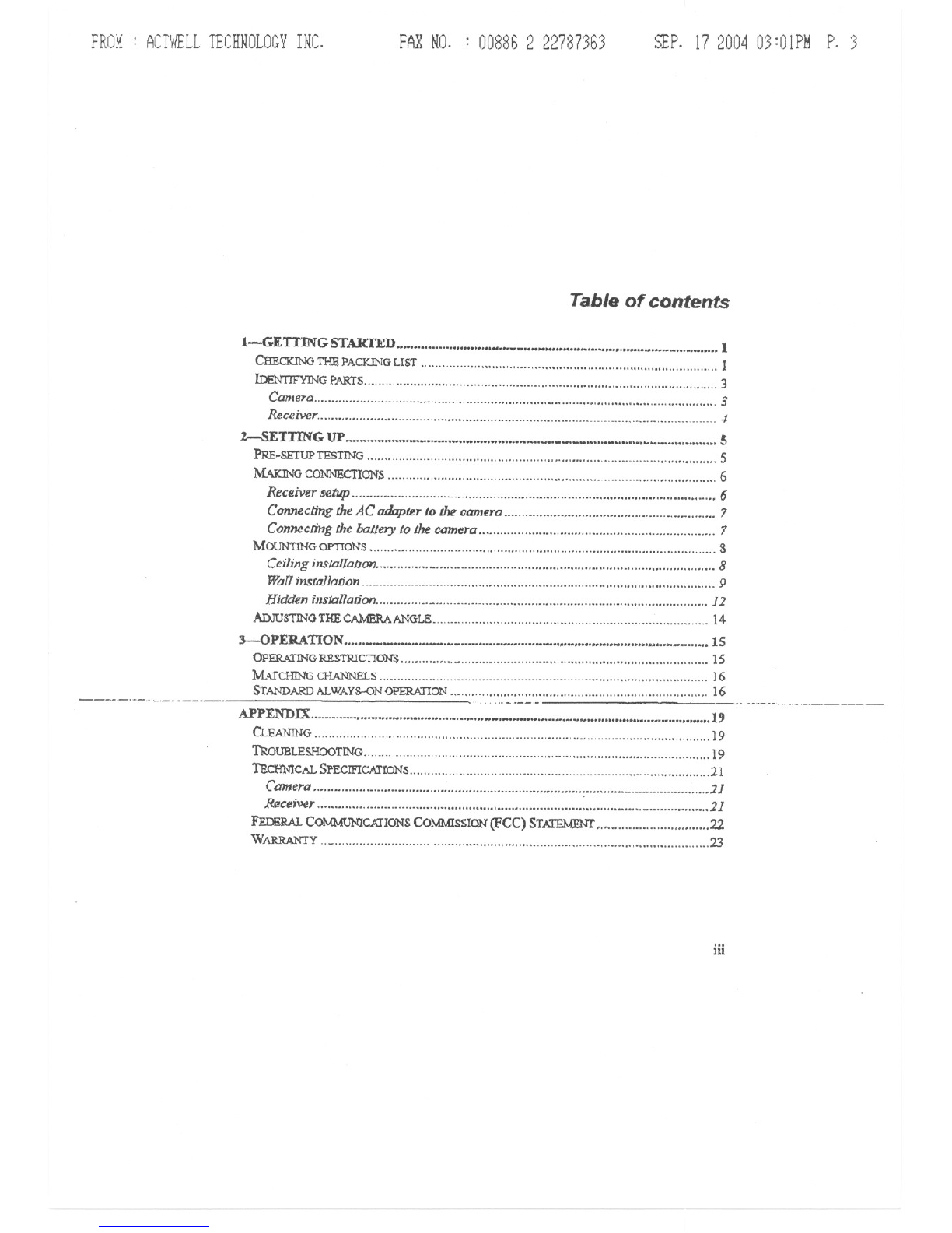
Table of contents
:I.-GETTINGSTARTED 1
CHECICINGTHEPACKINGLIST 1
lDENTIF'YINGPARfS 3
Camero 3
Rec2iver 1
%--SETTING UP is
PRE~SETUPTESTING 5
MAIaNGCONNECTIONS 6
Receiver setup"""""""'" 6
Connecling the AC adopter to the camera 7
Connecring the baLler}'to the camera 7
MOUN!INGOPTToNS S
CeilinginsJal/aiion " , 8
Wallinstal/anon "9
Hidden illstallauon 12
ADJUSTINGTHECA1vmRAANGLE 14
3--0 PERA TI ON """'" """ '" ,... ....,... "'" 15
OPERA1'ING:RESTRICTION:s 15
M6J'cHING CHA.NNE'1.S ""'" 16
STANDARDALWAYS--ONOPERATION"""""""""""""""""""""""""""""""""""'" 16
---'-'-"'-'.'....-..---..-- "" '---.........-.-.-----
APPENDIX.. ... 19
CLEANING 19
TROUBLESHOOTINO 19
TECH:NICALSPECIFICATIONS ""'" 21
Camera, , 11
Receiver ,2]
FmE1w.. COMMONlCIJIONSCOMMISSION(FCC) STATEMENT 22
WARRANTY , , 23
iii
FROM: ACTWELLTECHNOLOGYINC. FARNO. : 00886 2 22787363 SEP.17200403:01PMP.14
i-Getting started
Congratulationson your purchase of the remote camera. Use this camerato monitor
location!>wirelessly, as a stand-alene solution or integrated into an existing alarm
system.
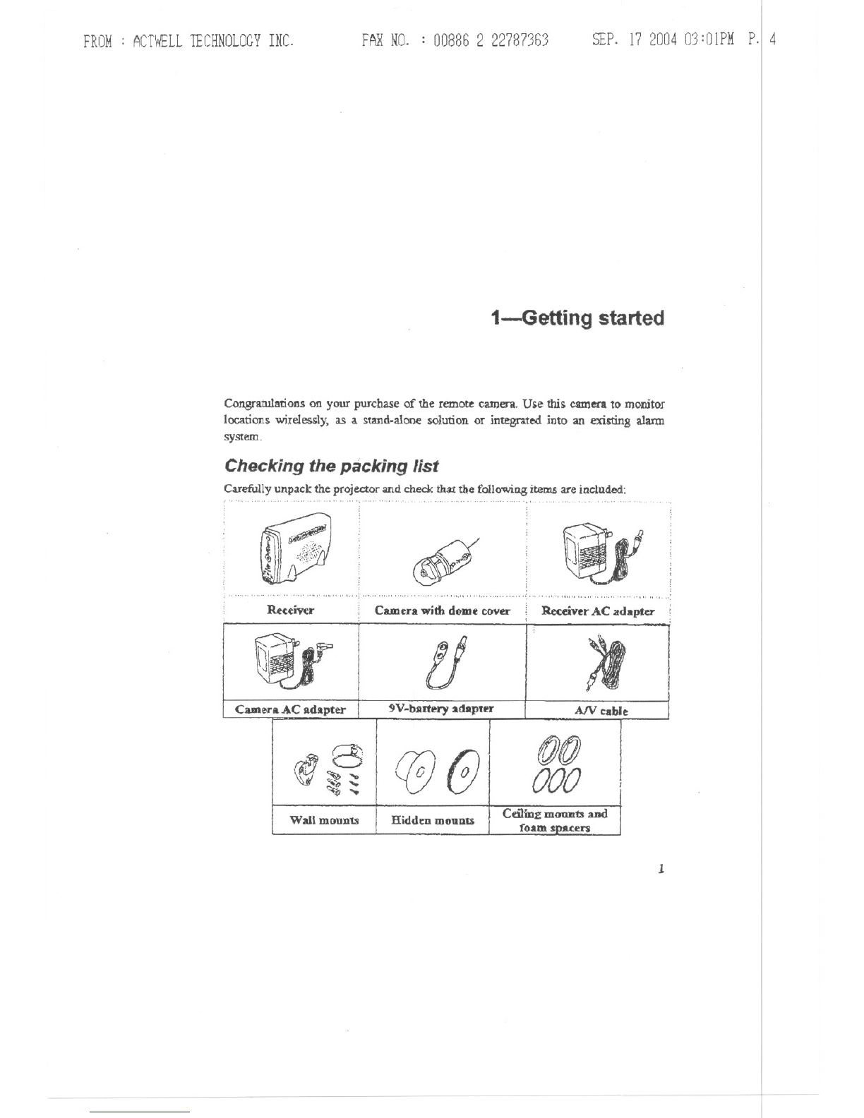
Checking the packing list
Carefully unpack the projector and check th3Xthe following items are included:
.'" ','"
c!P
",.., .."" ,:..,.. """","""'", ..",..,.."" " , .."", , :
Reuiver Camerawith dome cover: ReceiverACadapter
tJ ~
CameraAC adapter 9V-batteryadapter A/V cable
1
Bre (if @(f)
,000
c....
....
Wall mounts Hidden mounts Ceilinz mOUll1:ol and
foam s'Pa.c:el"$
FROM: ACTWELLTECHNOLOGYINC. FARNO. : 00886 2 22787363 SEP.17200403:01PMP.15
IbENrIFYING I'ARIS
-
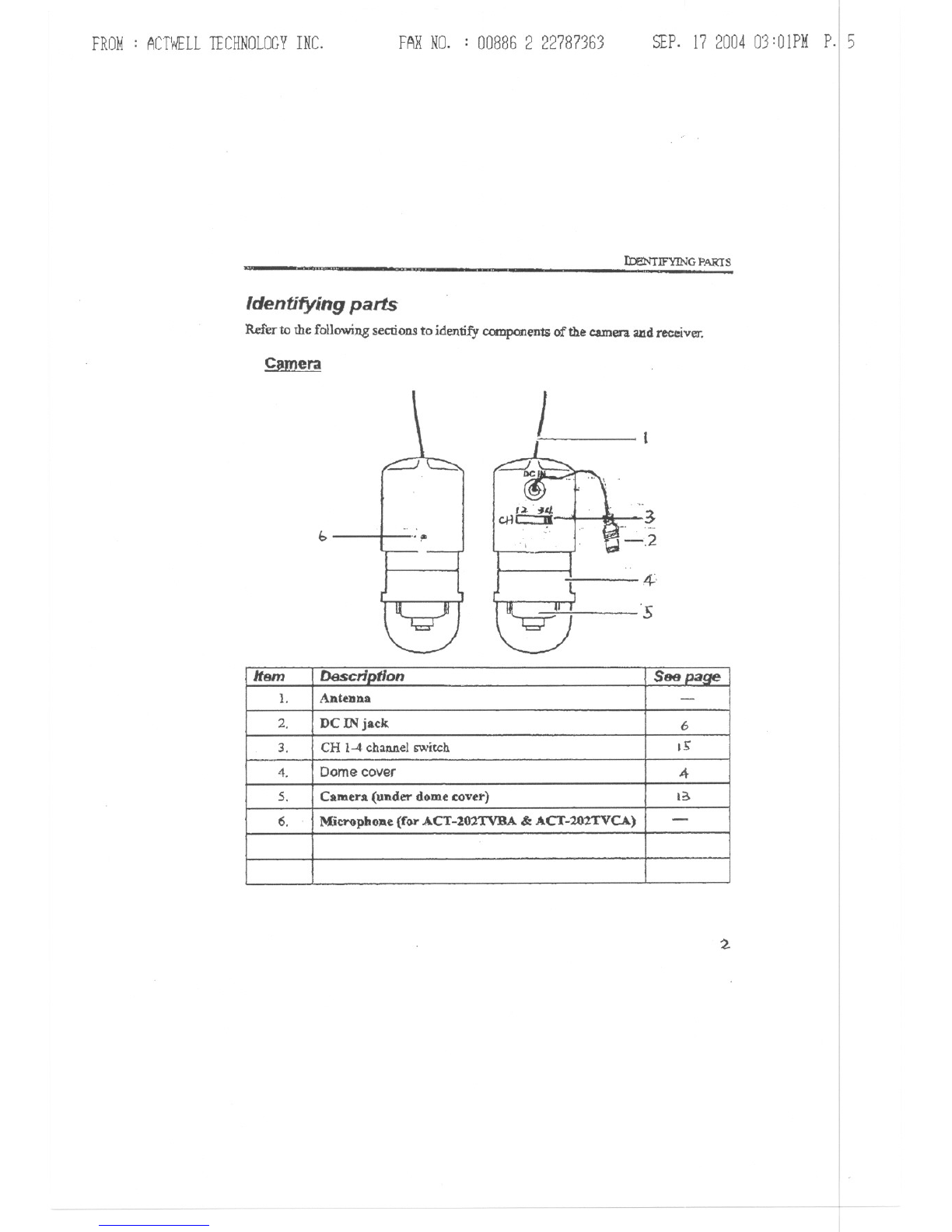
Identifyingparts
Refer to the following sections to identify components of the camera and receiver.
C!mera
b'. fI> 3
-,2
"
4,
's
2
Item D6scrlQtlon See Daile
1. Antenna -
2. DCINjack 6
3. CH 1-4channelswitch IS'
4. Domecover 4-
5. Camera (under domecover) I
6. l\{jcrophone(forACT-101TVBA&ACT-20ZTVCA) -

FROM: ACTWELLTECHNOLOGYINC. FAXNO. : 00886 2 22787363 SEP.17200403:OIPMP.16
I-GETTING STARTED
.. ~ ~
R~iver
7~O' ,~~
l; ~:
. I ,~
5,Dill
4-- \-1,*
~ ---r:- .'Ib
~
.:.:/:;X~X'
0..' . - _. ... .._..
3
-
Item Description See paQe
1. Speaker -
2. Socke!mouDt -
3. Audjo out jack 5
4. Video out jack 5
5. DC INjack S.
6. CB 1-4 chaaad switch IS'
7. ON power LED 15
FROM: ACTWELLTECHNOLOGYINC. FARNO. : 00886 2 22787363 SEP.17200403:02PMp.17
I
\
\
I
I
\
I
I
I
I
I
I
I
I
I
I
I
I
I
I
I
I
I
I
I
I
I
I
2-5etting up
This section explains the mounting options and setup of the wireless camera system.
However. before installing the camera. check that all the parts are working as
descn"bed below
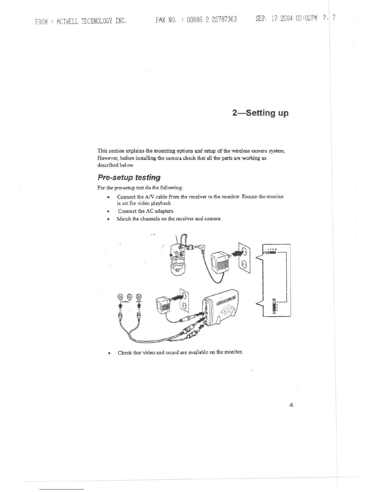
pre-setup testing
Por the pre-setUp test do the following:
.Connectthe A/V cablefrom the receiverto the monitor.Ensurethe monitor
is set for video playback.
.Connectthe AC adapters.
.Match the channelsonthe receiverand camera.
.Check that video and sound are available on the monitor.
1>~01
,-
00<
Ii
00
4
SEP.17200403:02PMp.18
I
I
I
I
I
I
I
I
I
I
I
I
I
I
I
I
I
I'
I
I
I
I
I
I
FROM: ACTWELLTECHNOLOGYINC. FARNO. : 00886 2 22787363
2-5ETIIN<t UP
-.If somefunctions doDotwork, checkthe correspondingsectionin this
manualbefore installing the camera.
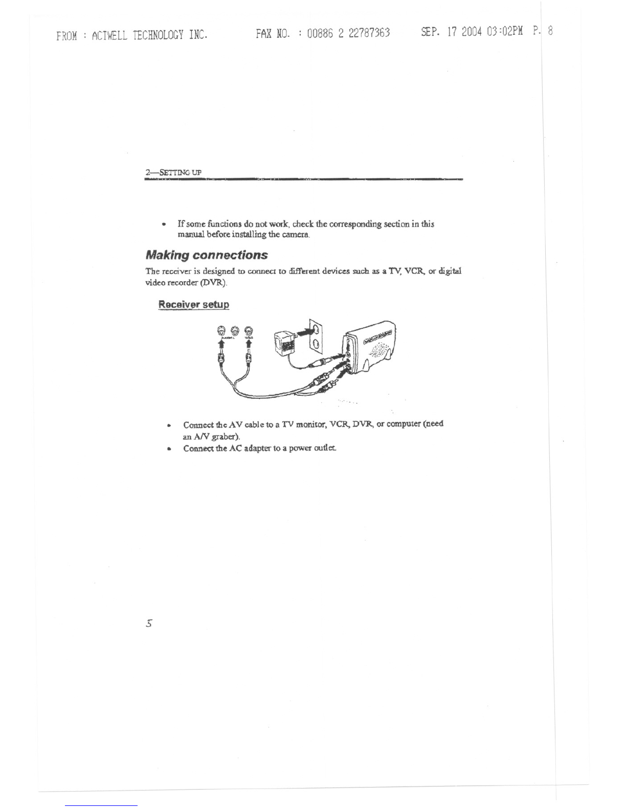
Making connections
The receiver is designed to connectto differentdevices such as a TV,VCR. or digital
video r~rder (DVR).
ReceiVJ'rsetup
.Connectthe AV cable to a TV monitor, VCR. DVR, or computer(need
an AN graber:).
.Conne<;tthe AC adapter to a power outlet.
s
------

FROM: ACTWELLTECHNOLOGYINC. FARNO. : 008862 22787363 SEP.17200403:02PMP. 9
MAKING CONNECTIONS
.. -
Connecting the AC adaDter to the camera
Use only the supplied AC adapter.
(:.pnnectlnathe batteN to the camera
Use a 9V battery.
~
-~

FROM: ACTWELL1ECHNOLOGYINC. FARNO. : 00886 2 22787363 SEP.17200403:03PMP.10
2-SETI1NG UP
Mounting options
Usingthe supplied accessories,the camera canbe mOUDted011a oeilingor wall. It can
also be mounted in a hidden location such as in a container or behind a partition.
Impor:tant: The dome cover holds the camera housing together. When yoo
remove the dome cOVet,take care that the camera Musing doeg
not separate.
CeiUnn installation
Before choosing a JocabOll for the ceiling installation. consider the following:
.You may need to install the camera ftom above, in which case two adjacent
tiles need to be removed for the installation.
.You mU&1hold the camerain positionfrom above the ceilingtile while
screwing the dome cover on,
Yau may need to adjust the camera angle before replacing the adjacent tile.
.
.Yau need a power source for 'the camera.
Refer to the following for the ceiling installation.
1. Remove the domecoverfromthe camera.
2. Cut a 27-mm diameterholein a ceilins tile with a circle cutter.
(Use a spadebit to drill a holein a wood panel.)
Put the camerain ttom thetop.
3.
~
~<g
?

FROM: ACTWELLTECHNOLOGYINC. FAXNO. : 008862 22787363 SEP.17200403:03PMP.ll
MOUNTING omONS
4. Usefoam spacersto ensure the dome coverscrews on securely.A
thinner ceiling tile may require more than one foam ring; a thicker
ceiJjng tile may require none at all.
Adjust the camera angle.(See UAdjustingthe cameraangle" on
page 13 )
Screw the dome cover onto the c.aroera.
5.
6.
Wall instaUation
Before choosing a location for the wall installation, consider the following:
.Yau need a power source for the camera. Check that the cable length on the
supplied AC adapter is long enough to reach your power source before
driUing holes.
.
Does the location you choose to install the camer&.allow easy access to the
camera? The camera dome must be removed and the camera taken out of the
wall brackct to connect to DC IN.
The wall bracket is designed so that cables cannot be unplugged from the
camera once installed. However, if you need to access the DC IN jacks often,
ccmsider fixing a block of wood behind the bracket so there is.moce space
between the jacks and the wall.
.
1.
2.
Remove the dome coverfrom the camera.
Put the wall moWlt ring on the cameC3.
The wall mount ring and camera are keyed to connect only oneway.
8

FROM: ACTWELLTECHNOLOGYINC. FARNO. : 00886 2 22787363 SEP.17200403:03PMP.12
2-SETrING UP
<:f!!t
3.
4.
Replacethe dome cover.
Plug the AC adapter into the camera. (See page b for using a battery
to power the caJ.D~.)
Align the mounting bracket on dIe surface and mark the three holes
wid! a sharpened pencil.
s.
q
FROM: ACTWELLTECHNOLOGYINC. FARNO. : 008862 22787363 SEP.17200403:03PMP.13
MOUNrJNG OPTIONS
$.,,'<0: ~
0.. ~"
;~.. /,=
...~.:,\ ~
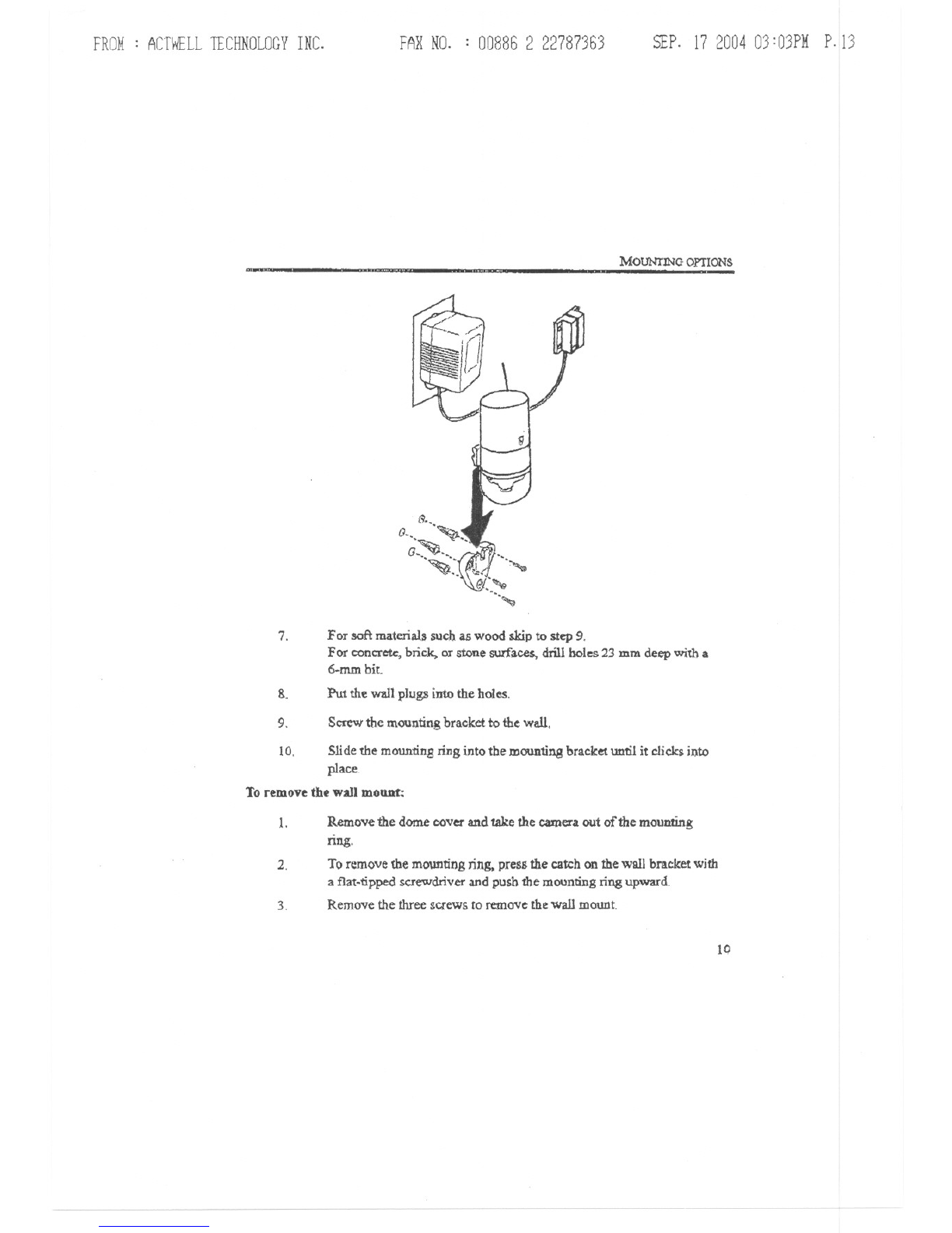
7. For soft materials such as wood skip to step 9.
For concrete, brick. or stone surfaces, drill holes 23 mm deep with a
6.mm bit.
Put the wall plugs into the holes.
8.
9. Screwthe mountingbracket to the wall
10. Slidethe mountingring into the mountingbracketuntil it clicksinto
place
Toremovethewall mount:
1. Remove the dome cover and take the camera out of the mounting
nng.
To remove the mounting ring, press the catch on the wall bracket with
a flat-npped screwdriver and push the mounting ring upward
Remove the three screws to remove the wall mount
2.
3.
10
FROM: ACTWELLTECHNOLOGYINC. FARNO. : 00886 2 22787363 SEP.17200403:04PMP.14
2-SRT!lNG UP
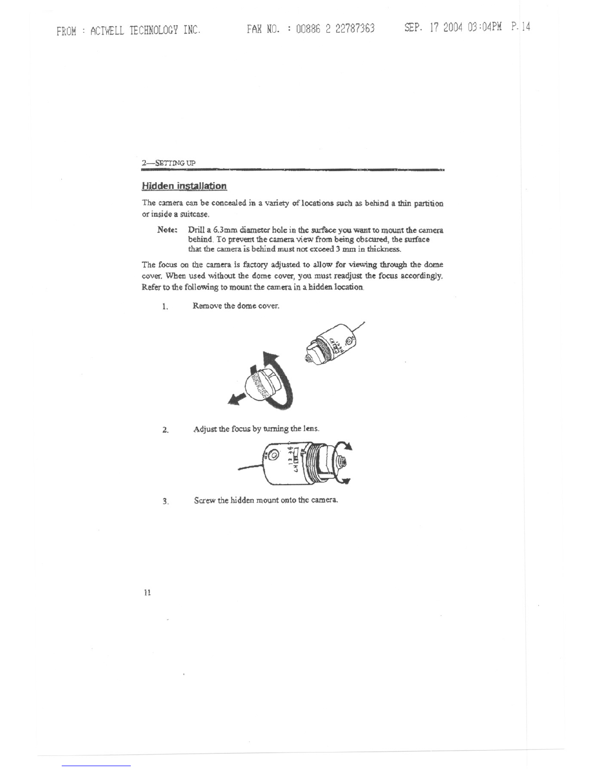
H-ldden installation
The camera can be concealedin a variety of locations such as behind a thin partition
orinside a suitcase.
Note: Drill a 6.3mm diameter hole in the sw:face you want to mount the camera
behind. To prevem the camera view from being obgcured, the surface
that the camera is behind must not exceed 3 mm in thickness.
The Cocus on the camera is factory adjusted to allow for viewing through the dome
cover. When used without the dome cover, you must readjust the focus accordingly.
Refer to the following to mount the camera in a hidden location.
1. Remove the dome cover. ~
2. Adjust the focug by turning the lens.
3. Scr~ thehiddenmount ontothe camera.
11
FROM: ACTWELLTECHNOLOGYINC. FARNO. : 00886 2 22787363 SEP. 17 2004 03:04PM P.15
MOUNTING OPTIONS
---t.,.
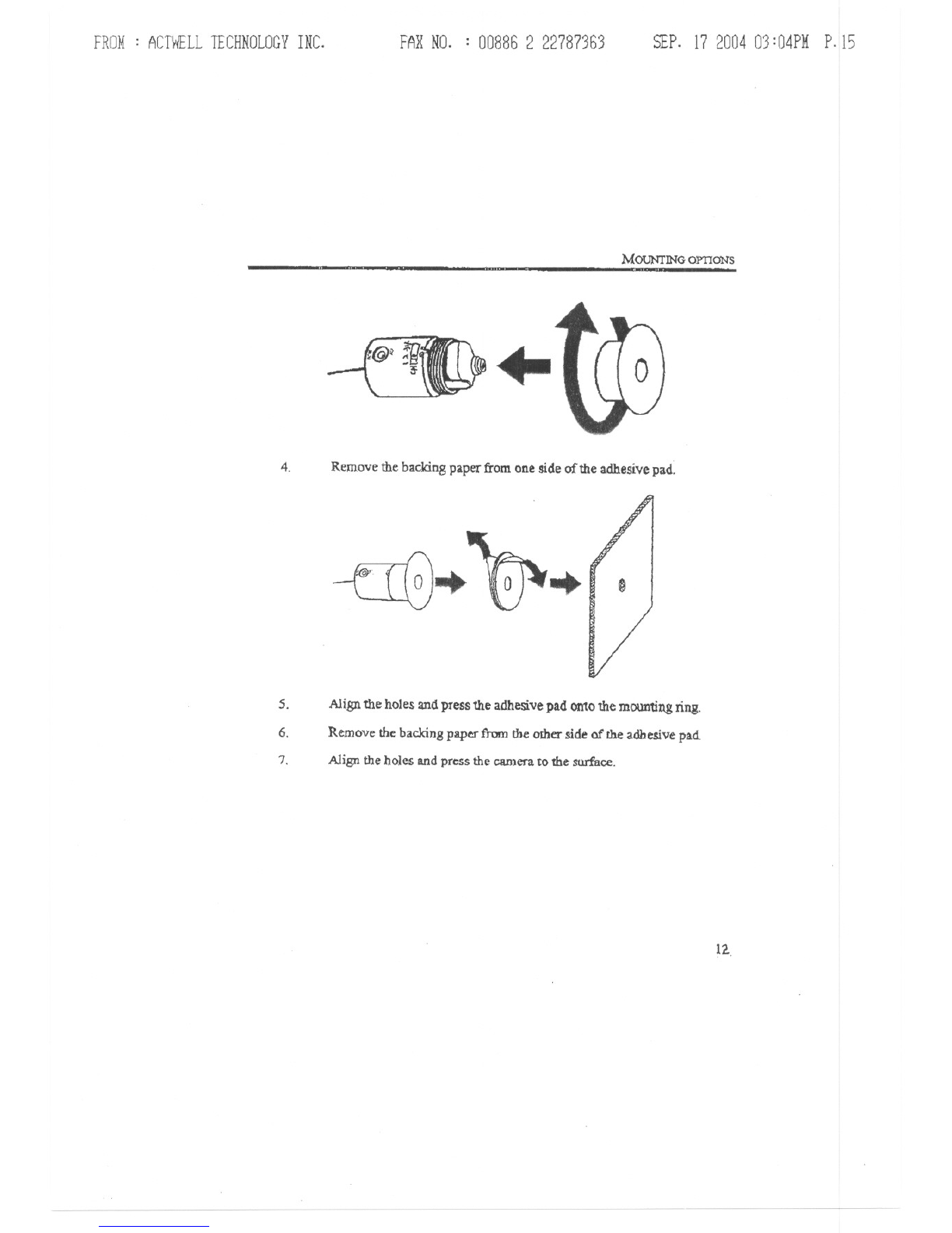
4.Removethe backing paper from one side of the adhesive pad.
--rIG... ~... D
s. Align the holes and press the adhesive pad onto the mounting ring.
Remove the backing paper from the other side of the adhesive pad.
6.
7. Align the holes and press the camera to the surface.
12..
FROM: ACTWELLTECHNOLOGYINC. FARNO. : 00886 2 22787363 SEP.17200403:04PMP.16
2-SETTING UP ..
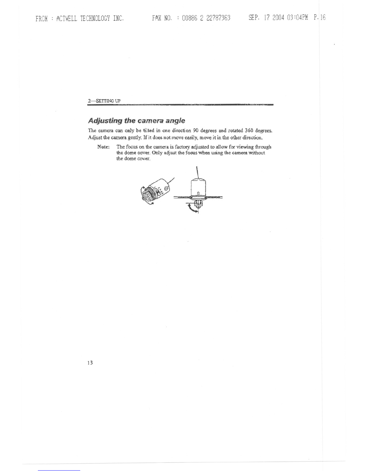
Adjusting the camera angle
The camera can on1y be tilted in one direction 90 degrees and rotated 360 degrees.
Adjust the camera gently. If it does not move easily, move it in the other direction.
Note: The focus on the camera is factDrYadjusted to allow for viewing through
the dome coVet'.Only adjust the focus when using the camcn without
the dome COVcI".
13

FROM: ACTWELLTECHNOLOGYINC. FARNO. : 008862 22787363 SEP. 17200403:05PMP.17
3-Operation
The chapter describes the operation of the remote camera.
Operating restrictions
. On1yuse 9V batterieswith the adapter.
.Avoid using the camera in humid locations. If conden5ation occurs, allow the
camerato dry before operating. .
Do not USein tempera1ures below -10 degrees Celsius or above 55 degrees
Celsius.
Proximity to microwave ovens can cause interference and reduce the quality
of the audio and video signals
.
.
.Using two cameras in the same vicinity may result in sound and pic.ture
interference.
IIJ-
FROM: ACTWELLTECHNOLOGYINC. FARNO. : 008862 22787363 SEP.17200403:05PMP.IS
3-<>PBR.AnON
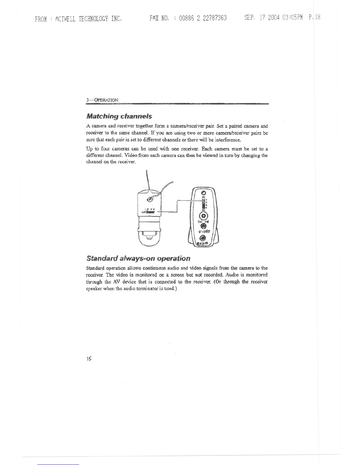
Matching channels
A camera and receiver together fonn a camera/receiverpair. Set a paired camera and
rece.ver to the same channel.If you are using two or morc cameralreceivcrpairs be
sure that eachpair is set to differentchannelsor there will be interference.
Up to four cameras can be used with one receiver. Each camera must be set to a
differentchannel. Videofrom each camera can then be viewed in turn by changingthe
channelonthe receiver.
,;: ~'o/.
GoI-
Standard always-on operation
Standardoperation aJlowscontinuous audio and video signals from the camera to the
receiver.The video is monitored on a .!cr~ but not recorded. Audio is monitored
through the AV device that is connected to the receiver. (Or through the receiver
speakerwhenthe audio terminatoris used.)
16
-- ---

FROM: ACTWELLTECHNOLOGYINC. FARNO. : 008862 22787363 SEP. 17200403:O5PMP.19
Appendix
This appendix describes cleaning and troubleAhootiogproudures. Also covered are
technicalspecifications.FCC compliance.andwamnty iDf'onnation.
Cleaning
The lens can be wiped with a soft opticaJ cleaning cloth. The dome cover can be
cleanedwi1hglass cleaner.
..... .-- -..
Troubleshooting
There is no picture
on the 'creeD. 1. Make surepowercables areplugged in properly
andthat the outletshavepower.
2. Ensure thebattery on the camerais fresh
3. Make sure thatthe receiver is pluggedin.
4. Checkthat the AV cablesareproperly connected.
S. Ifusing a television,make surethat thecorrect
video channelis selected.
6. Make sure that the camera.andthe receiverare on
the samefrequency channel.
7. Ensurethat thereceiveris withinthe U:msmittiJ:1g
range of30Ometers(iDL-O-S).
\b

FROM: ACTWELLTECHNOLOGYINC. FARNO. : 00886 2 22787363 SEP.17200403:05PMP.20
APPENDIX
i'T
The picture 1. Ensure the batteJyon the camera is fresh.
quality is poor. 2. Make sure'thennO1hingis obstroctingthe camera.
... Don't use the cameranear a microwaveoven.
.
4. Make sure thereis sufficienttight.
S. Don't u morethan one camerain the same
vicinity.
Tben: is .. picture 1. Check thevolume OIlthe receiver and the &udi<)
but no soliDd. device.
2. Ensurethe battefy on the camerais fresh.
3. Checkthat the audio cableis properlyp1uggedin to
the rcceiverand the audiodevice.
4. Check that the audio terminator(if used) is securely
plugged in.
There is sound but 1. Ensure the battery011thecamerais fresh.
DOpicture. 2. Check thatthe video cableis properly connectedto
the receiver and the monitor.
3. Checkthe brightnessonthe display.
The alarm does 1. Make cemin the sensor cable is pluggedin andthat
not turn ofTor on. the connectionto the scm.soris secure.
(tor ACT-103TX) 2. Checkto seeme NC NO swi1Chis inthe intended
position.
3. If using the reed switch,make surethe contactsare
close enoughfor the switch to operate properly
4. Ifusing a differentsensor,follO\"1the
manufaCtUrer'stroubleshootingsteps.
Lines appear on Ma.b; sure there is no microwaveoperatingnearby.
the screen.
The picture is Relocatethe recciverto avoidobstaclessuch as
ghosting. trees orbuildings.
The R/C cable 1. Make certa1ntheRlC cable is pluggedin and that
does not initiate the connectionto tbescnsor is secure.
recording. 2. Checkto see the NC NO switchi in the intended
(for .ACT-203TX) position.
This manual suits for next models
1
Table of contents


