Acucraft Outdoor Linear 8 Burner System Administrator Guide
Installation/Operator’s Manual
Rev5
www.acucraft.com 888-317-6499
OUTDOOR LINEAR 8
BURNER SYSTEM
Natural Gas
Complies with ANSI Z21.97-2014 / CSA 2.41-2014
SAMPLE

2
TABLE OF CONTENTS
Introduction ......................................................................... pg 3
Safety / Warnings ................................................................ pg 4
Installation Guide
System Illustration ................................................................. pg 5-9
Wiring Diagrams .................................................................... pg 10
Connecting the Gas Valve & Ignition System ........................ pg 11
Installing the Media ............................................................... pg 12
Operation Guide
Instructions ............................................................................ pg 13
Lighting Instructions................................................................ pg 14
Troubleshooting ..................................................................... pg 15-16
Caution .................................................................................. pg 17
Maintenance & Care .............................................................. pg 18
Specications ........................................................................ pg 19-20
Notes ..................................................................................... pg 21
Warranty ............................................................................... pg 22
SAMPLE

3
INTRODUCTION
Dedication to innovation, honesty, excellence, and hard work ensure that we can provide
solutions to each and every one of our customers.
Our team stays up-to-date on all the latest trends and technologies to ensure we can
provide customers with the perfect solution for their project. Our passion for excellence paves
the way for our world-class products, systems & customer service. Our goal is to revolutionize
the replace industry not by being the biggest, but by being the best. We push ourselves to do
more than we think we are capable of. We are a family rst organization, and we strive to be
good stewards locally, nationally, and internationally.
Please review this manual carefully before installing your new replace.
Model: Outdoor Linear 8 Burner System (NG)
www.acucraft.com 888-317-6499
Acucraft Fireplaces
19672 172nd Street
Big Lake, MN 55309
SAMPLE
4
Carbon Monoxide Poisoning: Early signs of carbon mon-
oxide poisoning resemble the u, with headaches, dizzi-
ness, or nausea. If you have these signs, the system may
not be working properly.
Get fresh air at once! Have the system serviced. Some
people are more affected by carbon monoxide than others.
These include pregnant women, people with heart or lung
disease or anemia, those under the inuence of alcohol,
and those at high altitudes.
Natural Gas: Natural gas is odorless. An odor making
agent is added to the gas. The odor helps you detect a gas
leak. However, the odor added to the gas can fade. Gas
may be present even though no odor exists.
Make certain you read and understand all warnings. Keep
this manual for reference. It is your guide to safe and prop-
er operation of this appliance.
HIGH ALTITUDE INSTALLATIONS:
The appliance is rated for installation up to 4500’ (1372m)
above sea level. Above 4500’ the appliance must be
de-rated at the factory for the appropriate altitude.
LOCAL CODES
Install and use the system with care. Follow local codes.
In the absence of local codes, use the latest edition of The
National Fuel Gas Code ANSI Z223.1/NFPA 54 available
from:
• American National Standards Institute Inc,. 1430
Broadway, New York, NY 10018
• National Fire Protection Association Inc., Batterymarch
Park, Quincy, MA 02269.
SAFETY
SAFETY STATEMENTS:
Safety is very important and is referenced throughout
this manual in different ways. There are two different
safety levels that you should be aware of. Warning
statements will occur when there is a possibility of
bodily harm present. Caution statements will occur
when there presents a risk of damage to the unit if
the statements are not followed correctly. Below are
examples of what the statements look like.
This appliance should be inspected
before use and at least annually by
a qualied service person. More fre-
quent cleaning may be required as
necessary. It is imperative that the
control compartment, burners and
circulating air passageways of the
appliance be kept clean.
WARNING
Carbon monoxide poisoning may
lead to death!
DANGER
1. This appliance, as supplied, is only for use with the
type of gas indicated on the rating plate.
2. When an appliance is for connection to a xed piping
system, the installation must conform with local codes,
or in the absence of local codes with the National Fuel
Gas Code, ANSI Z223.1/NFPA 54, or International Fuel
Gas Code, Natural Gas Installation Code CSA B149.1.
3. Keep the appliance area clear and free from combus-
tible materials, gasoline and other ammable vapors
and liquids.
4. Do not burn solid fuel in the replace after installing the
appliance. Do not use this appliance to cook food or
burn paper or other objects.
5. Children and adults should be alerted to the haz-
ards of high surface temperatures and should stay
away to avoid burns or clothing ignition.
6. Clothing or other ammable materials should not
be hung from the appliance, or placed on or near
the appliance.
7. Young children should be carefully supervixed
when they are in the area of the appliance.
8. The appliance, when installed, must be electrically
grounded in accordance with local codes or, in the ab-
sence of local codes, with the National Electrical Code,
ANSI/NFPA 70, if applicable.
9. Do not use appliace if any part has been under
water. Immediately call a qualied service techni-
cian to inspect the room appliance and to replace
any part of the control system and any gas control
which has been under water.
10. Inspect the burner before each us of the system. The
burner must be replaced prior to the appliance be-
ing put into operation if it is evident that the burner is
damaged. For replacement please contact Acucraft at:
11. Turn the appliance off and let cool before servicing,
installing, or repairing. Any guard or other protectice
device removed for servicing the appliance must
be replaced prior to operating the appliance. Only
a qualied service person should install, service, or
repair the appliance.
WARNING
Any change to this appliance or its
controls can be dangerous.
SAMPLE
5
INSTALLATION GUIDE
5
Note: The installation of this product must conform with local codes or, in the absence of local codes, the cur-
rent National Fuel Gas Code - ANZI Z223.1 (NFPA 54) Installation Code. Please check local codes before
installation.
NOTE TO INSTALLER:
1. This appliance is for OUTDOOR USE ONLY. DO NOT install or use this appliance inside a building, garage
or any other enclosed area, including recreational vehicles and/or boats. This unit must be installed in
such a manner that the combustion air intake at the base of the unit remains clear and free of all ob-
structions at all times and during all weather conditions.
2. FOR NATURAL GAS: The minimum inlet pressure is 0.25 psi and the maximum inlet gas-supply pressure
is 2.0 psi. The normal operating inlet pressure is 7” WC. DO NOT INSTALL THIS UNIT IF MINIMUM PRES-
SURE IS NOT AVAILABLE OR IF MAXIMUM PRESSURE IS EXCEEDED.
3. Gas piping system must be sized to provide minimum inlet pressure at the maximum ow rate (BTU/hr).
45,000 to 60,000 BTU’s based on the desired ame height. Undue pressure loss will occur if the pipe is too
small, or the run is too long.
4. The appliance and its appliance main gas valve must be disconnected from the gas supply piping system
during any pressure testing of that system at test pressures in excess of 1/2 psi (3.5 k/Pa). The appliance
must be isolated from the gas valve supply piping system by closing the equipment shutoff valve during any
pressure testing of the gas supply piping system at test pressures equal to or less than 1/2 psi (3.5 k/Pa).
• Do not store or use gasoline or other ammable vapors and liquids in the vicinity of this or any other appli-
ance.
• WHAT TO DO IF YOU SMELL GAS
• Do not try to light any appliance
• Do not touch any electrical switch; do not use any phone in your building
• Immediately call gas supplier from a neighbor’s phone. Follow the gas supplier’s instructions.
• If you cannot reach your gas supplier, call the re department.
• Installation and service must be performed by a qualied installer, service agency or the gas supplier.
WARNING
If the information in these instructions is not followed exactly, a re or explosion may
result causing property damage, personal injury or loss of life.
SAMPLE

6
INSTALLATION GUIDE
INSTALLATION SAFETY GUIDELINES
1. Installation and repair should be done by a qualied service person. The appliance should be inspected
before use and at least annually by a qualied service person. More frequent cleaning may be reuired as
necessary. It is imperative that the control compartment, burners and circulating air passageways of the
appliance be kept clean.
2. Carefully inspect for shipping damage. If any parts are damaged, call Acucraft at 763-263-3156.
3. Correct installation and proper placement of the unit and decorative media is crucial to safe performance of
the unit. See installation instructions for further information.
4. A listed manual gas shutoff device must be installed prior to the location of the replace.
TO INSTALL THE BURNER
The installation of this appliance must conform with local codes or, in the absence of local codes, with the Na-
tional Fuel Gas code, ANSI Z223.1/NFPA54, or the Natural Gas and Propane Installation Code, CSA B149.1.
Final assembly of this replace on site consists of the following main steps:
1. Positioning and securing of the re pit
2. Connecting the gas valve and ignition system
3. Installing replace media and replace glass panes, if applicable
POSITIONING THE FIREPLACE
• The burner is designed to sit directly on non-combustible materials
• Identify the location of the re pit
• Set the burner over the incoming gas line
Note: The appliance should be positioned in a manner that planned gas line access is available with adequate
clearance for servicing from the top of the re pit.
*Clearances must be in accordance with local installation codes and requirements of the gas supplier.*
SAMPLE

7
INSTALLATION GUIDE
GAS INFORMATION
Fuel - Before making gas connections ensure appliance being installed is compatible with the available gas
type.
Gas Pressure - Proper Input Pressures are required for optimum appliance performance. Gas line sizing re-
quirements need to be made following NFPA51.
Pressure Requirements for Appliance
(Natural Gas)
Minimum Inlet Pressure: 0.25 psi
Nominal Operating Inlet Pressure: 7” WC (NG)
Maximum Inlet Pressure: 2.0 psi
Gas Connection - Have the gas supply line installed in accordance with local building codes, if any. If not, follow
ANSI 223.1. Installation should be done by a qualied installer approved and/or licensed as required by locality.
Note: A listed manual gas shutoff device must be installed prior to the location of the appliance.
Startup - A small amount of air will be in the gas supply lines. When rst lighting appliance it will take a short
time for air to purge from the lines. Subsequent lighting of the appliance will not require such purging.
Electrical Information
Note: The 24 volt transformer supplied is to be located in a remote location away from the re feature in an
approved weatherproof electrical junction box and installed in accordance with local codes.
Recommended Wire Size
No less than 12 gauge wire for all installations
Note: There are numberous electrical devices that can be used to turn the re feature on and off. Devices such
as wall switches and remote control devices that are used should be UL listed and approved devices for turn-
ing high voltage (110 v electrical power) on and off. This high voltage electrical power shall be connected to the
supplied 24 volt AC transformer by a qualied electrical installer.
WARNING
Check for Gas Leaks after installation complete
• Check all ttings and connections
• Do not use open ame to check for leaks
• Check for leaks with a commercially available, non-corrosive leak check solution
SAMPLE
8
INSTALLATION GUIDE
SAMPLE
9
INSTALLATION GUIDE
SAMPLE

10
INSTALLATION GUIDE
SAMPLE
11
INSTALLATION GUIDE
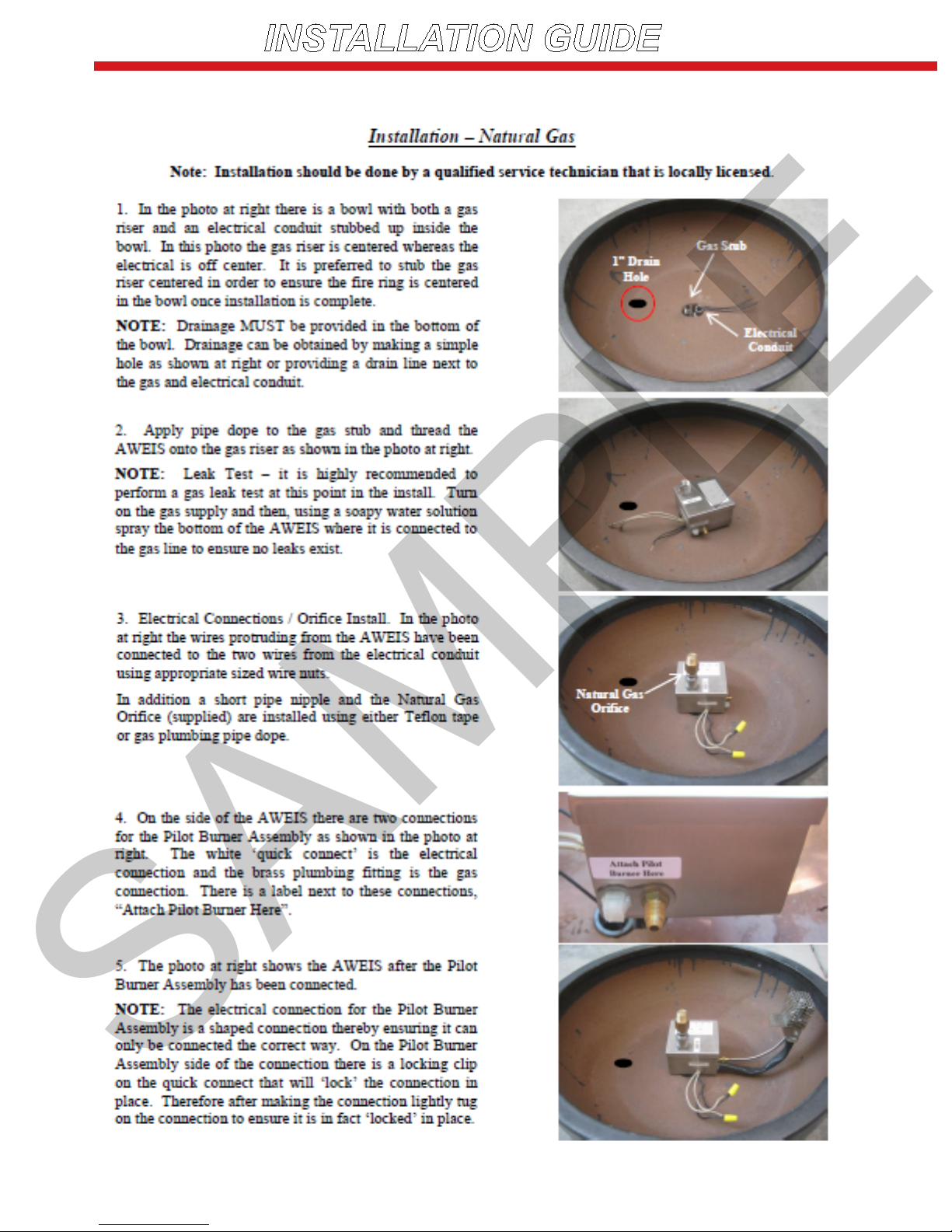
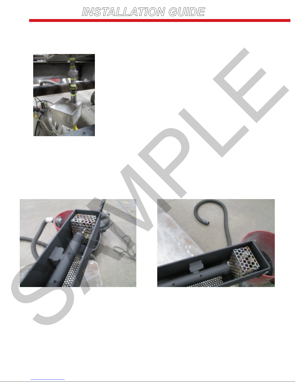
Control Box
Connection of the ignition system to the burner. On
the side of the AWEIS there are two connections for
the pilot burner assembly. The white “quick connect”
is the electrical connection and the brass plumbing
tting is the gas connection. There is a label next to
these connections, “Attached Pilot Burner Here.”
Connection of the wiring harness/pilot tubing exten-
sion is shown to the bottom of the igniter.
Pilot Assembly Mount
SAMPLE

12
INSTALLATION GUIDE
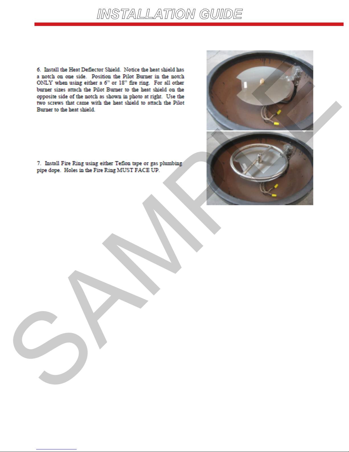
Installation of replace media and
glass panels:
This replace burner requires a layer of 1/4”
glass media to cover the burner tube, allowing
proper dissipation of the gas ow and prop-
agation of the ame. This should be spread
evenly across and completely covering the
burner located inside of the square burner tray.
Carefully place the glass media over the top of
the burner and mesh media tray located inside
of the square burner tray, allowing glass to ll
void alongside tube and to cover over the top
of the tube with approximately 1/4” of the 1/4”
glass media.
The photo to the left shows the nished look
that should be achieved with the glass media
over the burner.
SAMPLE
13
INSTALLATION GUIDE
OPERATING INSTRUCTIONS
WARNING
Do NOT use this appliance if any part has been under water. Immediately call a
qualied service technician to inspect the appliance and to replace any part of the
control system and any gas control which has been under water.
WARNING
Fire Risk / Burn Risk / HOT! DO NOT TOUCH
SEVERE BURNS MAY RESULT - CLOTHING IGNITION MAY RESULT
• Keep children away.
• CAREFULLY SUPERVISE children in the same area as the appliance.
• Alert children and adults to hazards of high temperatures.
• Clothing or other ammable materials should not be hung from the appliance or
placed on or near the appliance.
WARNING
This appliance should be inspected before use ant at least annually by a qualied
service person. More frequent cleaning may be required as necessary.
It is imperative that control compartment, burners and circulating air passageways of
the appliance be kept clean.
It is NOT recommended outdoor
re features be operated when
wind exceeds 25 mph.
CAUTION
SAMPLE

14
INSTALLATION GUIDE
LIGHTING INSTRUCTIONS
1. Prior to turning appliance on, visually inspect re feature to ensure debris such as leaves or other
combustible material has not collected inside the feature which could burn and emit embers once the
re feature is turned on. Also ensure any person standing close to the re feature is aware that you
will be turning the re feature on prior to actually turning it on.
2. Turn the re feature on by turning on the electrical device used to power the re feature:
• Sequence of Operation during Ignition:
• Power is applied
• Hot Surface Igniter (Glow Plug) becomes hot and Pilot Gas Valve opens
• Within 10 seconds of power application Pilot Flame should be visible (at night only)
• Within 10 seconds of Pilot Flame Ignition burner element (re ring/burner bar) should ignite
3. Turn re feature off by turning off the electrical device used to power the re feature.
SAMPLE

15
INSTALLATION GUIDE
TROUBLESHOOTING
Q: I installed the Electronic Ignition System, turned it on and nothing happened.
A: When this occurs it is usually due to an electrical wiring/power issue. Check all your electrical con-
nections thoroughly to ensure all wires at the transformer and inside the re feature are connected prop-
erly. If it appears all wiring is connected properly, disconnect the wires at the re feature, attach a Multi-
meter to the wires to conrm a minimum of 24 volts when the re feature is turned on. If you determine
that you do not have a minimum of 24 volts at the re feature conduct the same test at the transformer
to ensure the transformer is in fact producing a minimum of 24 volts. If you do have a minimum of 24
volts at the re feature contact Acucraft for further assistance: 763-263-3156.
Q: I installed the Electronic Ignition System, turned it on and I can see the glow plug glowing
orange and I can hear gas owing but it will not ignite.
A: There are two possible causes to this problem: Air in the Gas Line or not enough Electrical Current to
the re feature.
Air in the Gas Line. If a new gas line was installed and the air was never purged from it prior to install-
ing the Electronic Ignition System then it may take several times of turning the re feature on and off be-
fore the air is purged from the gas line. Here is how our system works: after you turn it on the glow plug
will come on rst followed by the Pilot Gas Valve opening 4 seconds later. For the next 180 seconds (3
minutes) the glow plug will cycle on and off every 30 seconds while the Pilot Gas Valve will remain on
the entire time. Therefore if you are attempting to purge air from the gas line, turn the system on and
leave it on for approximately 3 minutes. Usually when purging air from a new gas line you will need to
cycle the power several times as described above before gas begins to ow. If at any point you smell
gas but still don’t have ignition, attempt to light the Pilot ame with a handheld lighter. If the ame ignites
when you light it by hand, go to the section below: “Electrical Current.”
Electrical Current. If you have determined that air in the gas line is not the problem then most likely
the failure to ignite is due to the fact that the glow plug is not getting hot enough to ignite the gas. The
reason a glow plug will not get hot enough is due to the fact that it is not getting enough ‘amps.’ Often
times when troubleshooting electricians will check the electrical power and when they see they have a
minimum of 24 volts they think everything is ne electrically so there must be a problem with the Elec-
tronig Ignition System. The problem is not due to the volts but rather the amps. The number of amps
reaching the re feature is heavily dependent on the gauge wire used between the transformer and the
re feature. Our Install Instructions require no less than 12 gauge wire be run for all re features. Often
times we learn that in many cases less than 12 gauge wire has been used and herin lies the cause of
the problem. (Continued on next page)
SAMPLE

16
INSTALLATION GUIDE
TROUBLESHOOTING
1. CAUTION. Turn off the gas supply prior to the next step.
2. Using a clamp on the ammeter, clamp the ammeter around one of the wires providing power to the
Electronic Ignition System.
3. Turn the re feature on.
4. The amps you should see will range between 1.4 to 1.6 amps initially. Four seconds after being
turned on the amps will jump to approximately 2.0 amps.
If you do not see the amps listed above AND the wire gauge used was less than 12 gauge wire - change
the wiring. Otherwise contact Acucraft for further assistance: 763-263-3156.
SAMPLE

17
INSTALLATION GUIDE
CAUTION
• Due to high temperatures, the appliance should be located out of trafc and away from furniture and
draperies
• Children and adults should be alerted to the hazards of high surface temperatures and should stay
away to avoid burns or clothing ignition
• Young children should be carefully supervised when they are in the same room as the appliance.
Toddlers, young children and others may be susceptible to accidental contact burns. A physical bar-
rier is recommended if there are at-risk individuals in the house. To restrict access to a replace or
stove, install an adjustable safety gate to keep toddlers, young children and other at-risk individuals
out of the room and away from hot surfaces
• Clothing or other ammable material should not be placed on or near the appliance
• Installation and repair should be done by a qualied service person. The appliance should be in-
spected before use and at least annually by a professional service person. More frequest cleaning
may be required due to excessive lint from carpeting, bedding material, etc. It is imperative that con-
trol compartments, burners, and circulating air passageways of the appliance be kept clean
• Do not use this appliance if any part has been under water. Immediately call a qualied service
technician to inspect the appliance and to replace any part of the control system and any gas control
which has been under water
• This appliance is only intended for operation in temperatures above 32° F
• When shutting the unit down - be sure to TURN THE CONTROL VALVE FULLY OFF
• Every time you use the unit, make sure that:
• The area around the unit is clear and free from combustible materials, gasoline and other am-
mable vapors and liquids
• There is no blockage of the airow through the vent openings
• WARNING: HOT WHILE IN OPERATION AND FOLLOWING OPERATION. Serious injury can occur!
DO NOT throw trash, paper, or other ammable materials onto the unit. DO NOT leave in operation
when unattended
SAMPLE

18
INSTALLATION GUIDE
MAINTENANCE AND GENERAL CARE
• Examination and inspection of the appliance and all components including the burner, should be
performed annually by a qualied service technician
• Examination and visual check of the burner & ame should be performed periodically to ensure prop-
er operation
• Replacement of worn, broken, or non-functioning components should be left to a qualied service
technician
• If glass panels suffer any type of impact, immediately cease use of re pit until a qualied technician
can assess the integrity of the panels and determine if they need replacement before continued use
• The area around the appliance must be kept clear and free from combustible materials, gasoline,
and other ammable vapors and liquids
• The unit should be inspected regularly. Excessive debris can build up on this unit from leaves, dirt,
or other debris. It is critical that all control components, burners, burner screen and vent optining be
kept clean and free of all obstructions.
WARNING
• Follow lighting instructions provided in this manual.
• Never use abrasive cleaners to clean the glass.
• Do not clean appliance when hot.
• Clean the tempered glass with a basic household glass cleaner. Never use glass
cleaner that contains ammonia, as it may etch the tempered glass.
SAMPLE

19
PRODUCT SPECIFICATIONS
104 3
8
"
1"
1"
41
2
"
52 3
16
" INLET
2"
1"
3
8
"
1
2
"
3
8
"
CONNECTING TAB
11
8
"
GAS INLET
3/4"
2
3
1
REVISIONS
REV.
DESCRIPTION
ECO
DATE
ITEM NO.
PART NUMBER
DESCRIPTION
QTY.
1
0774-04
BURNER TRAY
1
2
0774-01
BURNER TUBE
1
3
0774-019
FLANGE
2
D
C
B
A
A
B
C
D
1
2
3
4
5
6
7
8
8
7
6
5
4
3
2
1
MATERIAL:
PROPRIETARY AND CONFIDENTIAL:
THE INFORMATION CONTAINED IN
THIS DRAWING IS THE SOLE
PROPERTY OF ACUCRAFT. ANY
REPRODUCTION IN PART OR AS A
WHOLE WITHOUT THE WRITTEN
PERMISSION OF ACUCRAFT IS
PROHIBITED.
5/2/2017
TITLE:
SIZE
B
DWG. NO.
REV
DATE:
R.SHEPHERD
DRAWN BY:
UNLESS
OTHERWISE
SPECIFIED ALL
DIMENSIONS
ARE IN INCHES
A
0774-C-001
END BURNER
DO NOT SCALE DRAWING
SHEET 1
OF 1
Acucraft Fireplace Systems
19672 172nd Street
Big Lake, MN 55309
Page 6
19
SPECIFICATIONS
Depth = 2 1/2”
Length = 138 1/2”
Width = 4 1/2”
Appx Weight. = 200 lbs.
Gas Type = Natural Gas
Electrical = Single 15 AMP service
NATURAL GAS
Input Rating (BTU/hr) 0-1370 m = 125,000 BTUs/hr.
Minimum inlet pressure (in.w.c.) = 7.0 in. W.C.
Maximum inlet pressure (in.w.c.) = 10.5 in. W.C.
Based on testing that was performed,
the following results have been re-
corded.
Minimum Clearances to combustibles
Unit to back wall of enclosure = 4 feet
Unit to sidewall of enclosure = 4 feet
Unit top to enclosure top = 8 feet
SAMPLE
20
PRODUCT SPECIFICATIONS
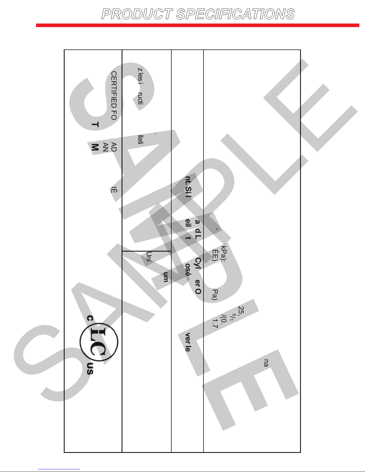
MANUFACTURER:
OUTDOOR DECORATIVE GAS APPLIANCE
Serial #/En Série: 0774-C-001
Acucraft Fireplaces MODEL/ MODELE: Outdoor Linear 8 Burner System
19672 172nd St Big Lake, MN 55309 (763) 263-3156
G
AS / TYPE DE GAZ: Natural Gas (Gaz naturel)
INPUT RATING (ENTRÈE NOTE) (Btu/hr) 0-610m: 125,000
ORIFICE SIZE (DIMENSIONS DE L’ORIFICE) (DMS) 0-610m: P
INPUT RATING (ENTRÈE NOTE) (Btu/hr) 610-1370m: 125,000
ORIFICE SIZE (DIMENSIONS DE L’ORIFICE) (DMS) 610-1370m: 5/16
MANIFOLD PRESSURE (PRESSION D’ADMISSION) (in. wc/kPa): 3.5/(0.9)
MINIMUM INLET PRESSURE (MINIMUM PRESSION D'ENTRÉE) (in. wc/kPa): 7.0/(1.74)
For Outdoor Use Only. If Stored Indoors, Detach and Leave Cylinder Outdoors.
Pour utlisation à l’extérieur seulement. Si l’appareil est entreposé à l’intérieur enleverles bouteilles et les laise
àl’extérieur.
Follow installation instruction.
Suivez les instructions d’installation.
Minimum clearances to combustibles:
U
nit to back wall of enclosure: 4 feet
U
nit to sidewall of enclosure: 4 feet
U
nit top to enclosure cap: 8 feet
CERTIFIED FOR CANADA/ CERTIFIÉ POUR LE CANADA
Lab Test
ANSI Z21.97, CSA 2.41-2014
DO NOT REMOVE THIS LABEL N'ENLEVEZ
PAS CETTE ETIQUETTE
SAMPLE
Table of contents
Popular Burner manuals by other brands


Napoleon
Napoleon HDX35 Installation and operation manual

Renaissance Cooking Systems
Renaissance Cooking Systems RJCSSB owner's manual

Bernzomatic
Bernzomatic UL2317 instruction manual

T&C
T&C TC36.NG03 installation instructions

Riello
Riello G5RT MC Installation, use and maintenance instructions

Riello
Riello G20D Installation, use and maintenance instructions