ACV Prestige ACVMax Owner's manual
2015-10 Prestige ACVMax Contro App . Sup .
This document is intended to be used by a factory trained and qualified heat-
ing contractor or service technician only. Read all instructions within this
document and within the PRESTIGE Boiler Installation and Maintenance
Manual before proceeding. It is recommended to follow the procedures in
the steps given. Skipping or missing procedural steps could result in severe
personal injury, death or substantial property damage.
prestige
Control Application
Supplement - ACVMax
Revised 12/15/2015
L
I
S
T
E
D
ARNING
2015-10 restige ACVMax Control Sup 12-14-15_ACVMax_Control 12/15/15 7:36 AM age 1

Tab e of Contents
i
PRODUCT AND SAFETY INFORMATION
Definitions ................................................................................................................1
1.0 - OPERATING INFORMATION
1.1 Entering Installer Access Code ......................................................................2
1.2 ACVMax Installer Menu Structure..................................................................3
2.0 - CH SETTINGS
2.1 Navigation ...............................................................................................5
2.2 Heating Operation ..........................................................................................5
2.3 Demand Type ...............................................................................................5
2.4 Absolute Max CH Setpoint .............................................................................6
2.5 CH1 Maximum Setpoint .................................................................................6
2.6 CH1 Minimum Setpoint ..................................................................................6
2.7 Outdoor Curve Coldest Day...........................................................................6
2.8 Outdoor Curve Warmest Day.........................................................................7
2.9 CH2 Circuit ...............................................................................................7
2.10 CH2 Maximum Setpoint .................................................................................7
2.11 CH2 Minimum Setpoing .................................................................................7
2.12 Warm Weather Shutdown ..............................................................................7
2.13 Circulation ump ermanent .........................................................................8
2.14 CH ost ump Time ......................................................................................8
2.15 Freeze rotection...........................................................................................8
2.16 Frost rotection Setpoint................................................................................9
2.17 arallel Shift Value .........................................................................................9
2.18 CH Call Blocking ............................................................................................9
3.0 - DH SETTINGS
3.1 Navigation ...............................................................................................10
3.2 DHW Operation ..............................................................................................10
3.3 Demand Type ...............................................................................................10
3.4 Boiler DHW Setpoint ......................................................................................11
3.5 DHW Setpoing ...............................................................................................11
3.6 DHW On Differential.......................................................................................11
3.7 DHW Storage Adder.......................................................................................12
3.8 DHW ost ump Time ...................................................................................12
3.9 DHW riority Timeout.....................................................................................12
3.10 DHW riority ...............................................................................................12
3.11 DHW Call Blocking.........................................................................................13
3.12 DHW To CH Call Blocking..............................................................................13
3.13 Antilegionella Function ...................................................................................14
4.0 - BOIlER SETTINGS
4.1 Navigation ...............................................................................................15
4.2 restige Model ...............................................................................................15
4.3 Lockout Temp. ...............................................................................................15
4.4 Modbus Address ............................................................................................16
4.5 ump Settings ...............................................................................................16
4.5.1 Current ump Configuration ..........................................................16
2015-10 restige ACVMax Control Sup 12-14-15_ACVMax_Control 12/15/15 7:36 AM age 2

Tab e of Contents - Continued
ii
4.5.2 reset ump Configuration (Solo) .................................................16
4.5.3 reset ump Configuration (Excellence) .......................................16
4.5.4 Flexible ump Configuration..........................................................16
4.5.5 Flex. Relay Configuration...............................................................17
4.5.6 Error Relay .....................................................................................17
4.6 Ignition Level NAT ..........................................................................................17
5.0 - RESET All SETTINGS
5.1 Navigation ...............................................................................................36
6.0 - FACTORY ACVMAx SETTINGS
6.0 Factory ACVMax Settings ..............................................................................37
7.0 - CASCADE
7.1 Cascade Operating Information .....................................................................38
7.2 ACVMax Cascade Menu Structure ................................................................39
7.3 Cascade Installation .......................................................................................40
7.3.1 System iping ................................................................................40
7.3.2 System Sensor Installation ............................................................40
7.3.3 Cascade Communication Cable ....................................................41
7.3.4 Low Voltage Wiring Connections ...................................................41
7.3.5 Line Voltage Wiring Connections ...................................................42
7.3.6 Cascade Autodetection ..................................................................42
7.3.7 Lockouts.........................................................................................43
7.4 Cascade Information ......................................................................................50
7.4.1 Navigation ......................................................................................50
7.4.2 System Temperature Logging ........................................................50
7.5 Cascade Settings ...........................................................................................51
7.5.1 Navigation ......................................................................................51
7.5.2 Stage Delay ...................................................................................51
7.5.3 Minimum Firing Rate......................................................................51
7.5.4 Boiler Enabling Algorithm...............................................................52
7.5.5 Boiler Disabling Algorithm ..............................................................52
7.5.6 Maximum Firing Rate.....................................................................52
7.5.7 CH/DHW Boilers ............................................................................53
7.5.8 Automatic Rotation.........................................................................53
7.5.9 CH roportional Gain.....................................................................54
7.5.10 CH Integral Gain ............................................................................54
7.5.11 DHW roportional Gain .................................................................55
7.5.12 DHW Integral Gain.........................................................................56
8.0 - MODBUS INTERFACE
8.0 Modbus Interface ...........................................................................................57
9.0 - MANUAl OPERATION
9.1 Navigation ...............................................................................................59
9.2 Fan ...............................................................................................59
9.3 CH1 ...............................................................................................59
9.4 DHW ...............................................................................................59
9.5 CH2 ...............................................................................................59
2015-10 restige ACVMax Control Sup 12-14-15_ACVMax_Control 12/15/15 7:36 AM age 3

(Page left intentionally blank)
iii
2015-10 restige ACVMax Control Sup 12-14-15_ACVMax_Control 12/15/15 7:36 AM age 4
Product and Safety Information
1
The following terms are used throughout this
manual to bring attention to the presence of
potential hazards or to important information
concerning the product.
Indicates the presence of a hazardous situa-
tion which, if ignored, will result in death,
serious injury or substantial property dam-
age.
Indicates a potentially hazardous situation
which, if ignored, can result in death, serious
injury or substantial property damage.
Indicates a potentially hazardous situation
which, if ignored, may result in minor injury
or substantial property damage.
Indicates special instructions on installation,
operation or maintenance, which are impor-
tant to the equipment but not related to per-
sonal injury hazards.
Indicates recommendations made by ACV-
Triangle Tube for the installers which will
help to ensure optimum operation and
longevity of the equipment.
ARNING
NOTICE
CAUTION
DANGER
BEST PRACTICE
DEFINITIONS
IMPORTANT INFORMATION - READ
BEFORE PROCEEDING
This document is intended to be used by a fac-
tory trained and qualified heating contractor or
service technician only. Read all instructions
within this document and within the PRES-
TIGE Boiler Installation and Maintenance
Manual before proceeding. It is recommended
to follow the procedures in the steps given.
Skipping or missing procedural steps could
result in severe personal injury, death or sub-
stantial property damage.
ARNING
ACV-Triangle Tube reserves the right to modify the technical specifications and components of its
product without prior notice.
NOTICE
This Control Application Supplement applies
to ACVMax controls with the following soft-
ware version numbers:
Display SWv.1.22
Burner Controller SW v.0.30
The software version numbers are displayed
on the initial screen after turning on the unit.
NOTICE
2015-10 restige ACVMax Control Sup 12-14-15_ACVMax_Control 12/15/15 7:36 AM age 1

2
1.0 Operating Information
1.0 OPERATING INFORMATION
The ACVMax Boiler Management System is designed to be flexible yet easy to use. ACVMax mon-
itors and controls the Prestige to operate as efficiently as possible. ACVMax monitors the boiler sup-
ply, return and flue gas temperatures and operates the igniter, gas valve and blower. ACVMax uses
this information to modulate the boiler’s firing rate to maintain the required setpoint.
ACVMax offers many advanced control options, which may be adjusted for various applications to
achieve optimum boiler efficiency and operation.
• Two central / space heating (CH) call inputs with separate outdoor reset curves.
• Two temperature central/space heating (CH) temperature control via optional mixing valve.
• Domestic Hot Water (DHW) call input with optional priority.
• System temperature sensing and control with an optional system temperature sensor.
• Cascade function allows up to six Prestige boilers to operate together in a single heating system.
• Modbus interface for integrating with building management systems.
These advanced features are adjustable in the Installer Menu after entering an access code.
2015-10 restige ACVMax Control Sup 12-14-15_ACVMax_Control 12/15/15 7:36 AM age 2

3
1.0 Operating Information
1.1 Entering Installer Access Code
Installer
Button
The INSTALLER button (the small round button) provides the installing contractor with full access
to all available features after entering an access code.
ENTER INSTALLER
ACCESS CODE
05[4]
Entering installer access code procedure
1. Press the round INSTALLER button.
2. Enter the installer access code “054” by using the LEFT and RIGHT
buttons to select a digit and the UP and DOWN buttons to change the
digit. Press the O button to enter the access code.
3. The Installer Menu will be displayed after successfully entering the
access code. The Home Screen will be displayed if the access code is
not entered correctly.
Entering the installer access code allows the installer to make adjust-
ments for 30 minutes. After 30 minutes, the access code will need to
be entered again to make any adjustments.
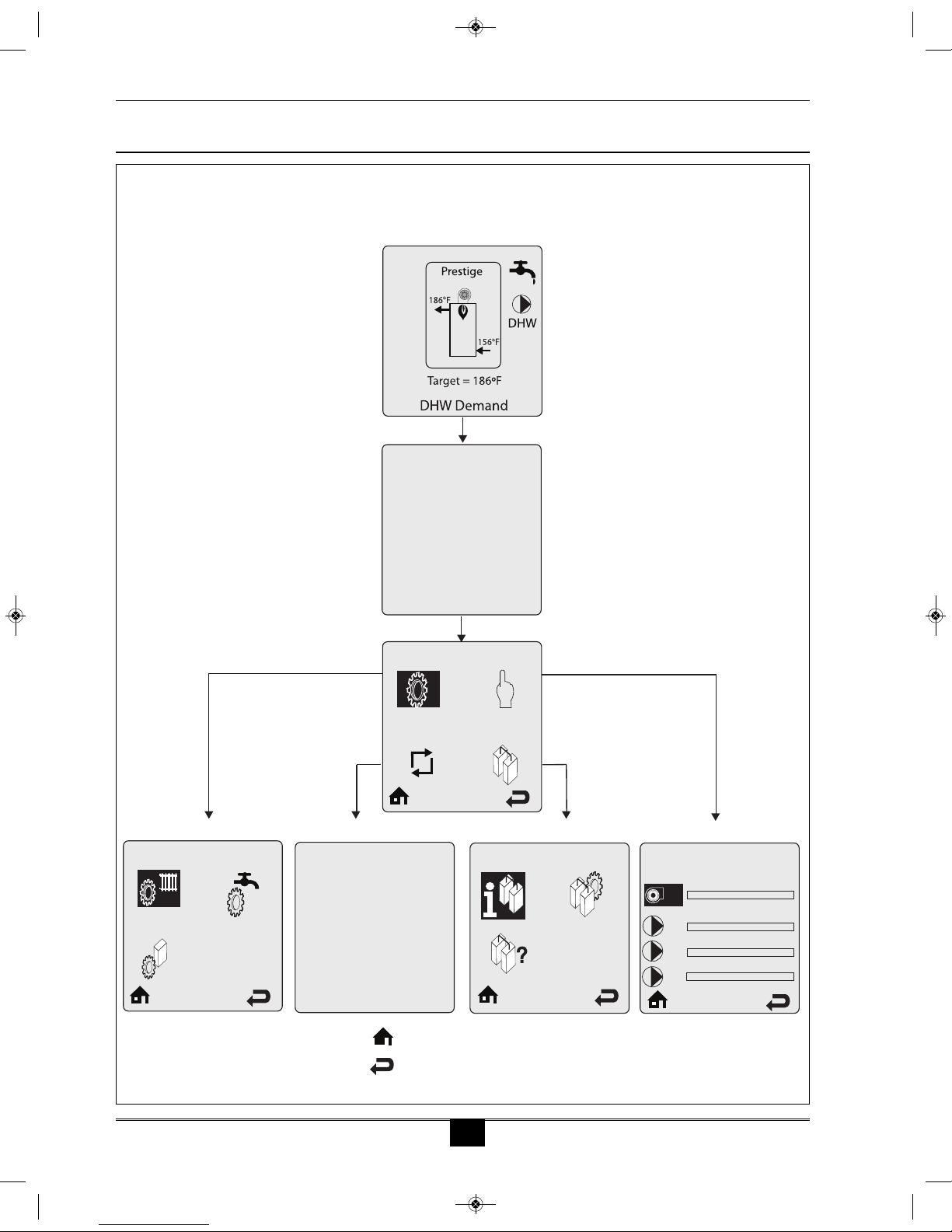
The Installer Menu is divided into four sections:
1. CH & DHW Settings – Allows the installer to adjust the boilers
central / space heating, domestic hot water and boiler settings for the
application. See pages 5 through 35.
2. Manual Operation – The burner and circulators can be manually
enabled for testing. See page 59.
3. Reset All Settings – Resets all CH, DHW, Boiler, and Cascade
Settings back to the factory defaults. See pages 36 through 37.
4. Cascade – Allows the installer to setup, adjust, and monitor the
Cascade System. See pages 38 through 56.
NOTICE
CH & DHW Settings
Fig. 1: ACVMax Navigation Buttons
2015-10 restige ACVMax Control Sup 12-14-15_ACVMax_Control 12/15/15 7:36 AM age 3
4
1.0 Operating Information
CH & DHW Settings
Home Screen
ENTER INSTALLER
ACCESS CODE
05[4]
CH & DHW Settings Menu Reset All Settings Cascade Menu Manual Operation
Installer Menu
Installer Access Code
CH Settings Reset All Settings
Press OK to restore factory settings,
any other button to keep current
settings
Cascade Info. Manual Operation
Released
O
O
O
CH1
FAN
DHW
CH2
Home - return to home screen
Back - return to previous screen
1.2 ACVMax Installer Menu Structure
2015-10 restige ACVMax Control Sup 12-14-15_ACVMax_Control 12/15/15 7:36 AM age 4
5
2.0 CH Settings
2.0 CH SETTINGS
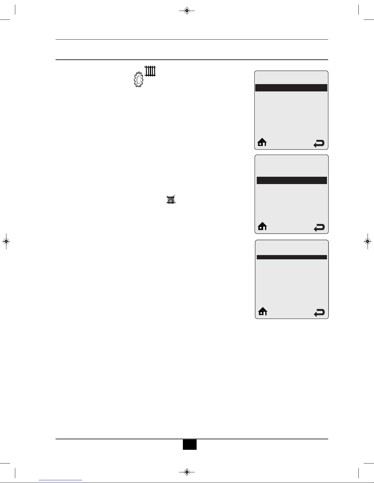
2.1 Navigation:
Home Screen > Installer Menu > CH & DHW Settings > CH Settings
The CH Settings menu contains settings related to central heating oper-
ation. Each line contains a CH Setting followed by its current value.
Six CH Settings are displayed on the screen at one time. Press the UP
or DOWN buttons to scroll through additional CH Settings.
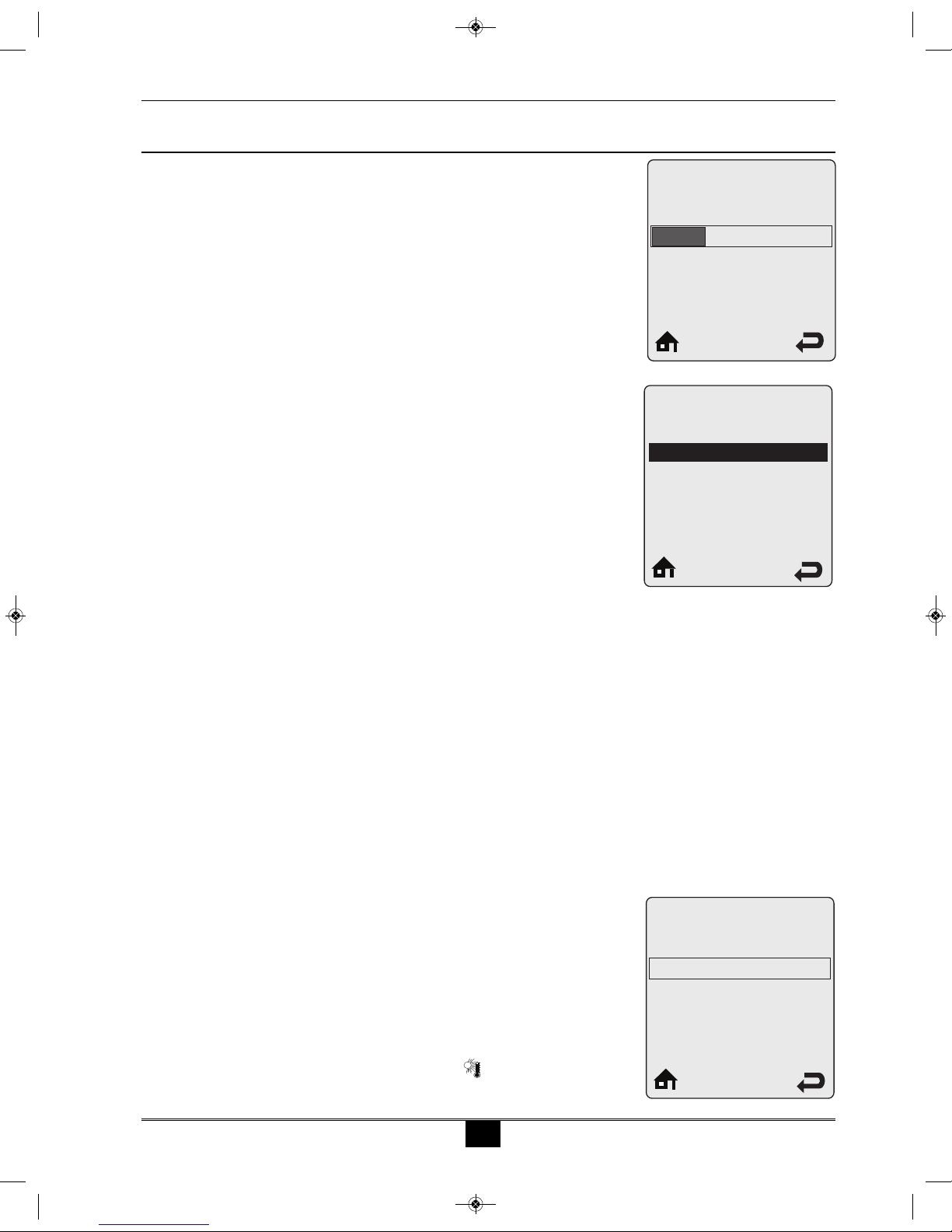
2.2 Heating Operation Default: Enabled
Heating Operation allows the central heating function to be enabled and
disabled. Press the UP or DOWN buttons to select Enabled or Disabled
then press the O button to store the setting.
•Enabled - The Prestige will respond to a central heating call.
•Disabled - The Prestige will not respond to a central heating call.
The heating operation disabled icon ( ) is displayed on the home
screen when central heating operation has been disabled.
Freeze protection will remain enabled when Heating Operation is
Disabled.
2.3 Demand Type Default: Thermostat & Outd. Curve
Demand Type allows the installer to select how a CH Demand is generat-
ed. Press the UP or DOWN buttons to select the CH Demand Type then
press the O button to store the setting. The CH Demand options are:
•Thermostat & Outd. Curve – A central heating call from a dry
contact switch will enable the Prestige and the setpoint will vary
with the outdoor temperature for central heating calls.
•Thermostat & Setpoint - A central heating call from a dry contact
switch will enable the Prestige and the setpoint will be fixed for
central heating calls.
•Constant & Outdoor Curve - The Prestige will maintain setpoint
and the central heating circulators will be constantly enabled with-
out an external call from a dry contact switch. The central heating
circulators will be disabled when the outdoor temperature exceeds
the Warm Weather Shutdown Temperature setting. The setpoint
will vary with the outdoor temperature for central heating calls.
•Constant & Setpoint - The Prestige will maintain setpoint and the
central heating circulators will be constantly enabled without an
external call from a dry contact switch. The central heating circula-
tors will be disabled when the outdoor temperature exceeds the
Warm Weather Shutdown Temperature setting. The setpoint will be
fixed for central heating calls.
•0-10V Modulation Signal – This option allows the Prestige firing rate
to be controlled by an external control system with a 0-10 VDC signal.
Heating Settings
Heating Operation
Demand
Abs.MaxCHSetpoint
CH1Max. Setpoint
CH1 Min. Setpoint
Outdoor Curve / Coldest Day
Enabled
Thermostat & Outd. Curve
188ºF
180ºF
120ºF
10ºF
Heating Operation
Disabled
Enabled
Demand Type
Thermostat & Outd. Curve
Thermostat & Setpoint
Constant & Outdoor Curve
Constant & Setpoint
0-10V Modulation Signal
2015-10 restige ACVMax Control Sup 12-14-15_ACVMax_Control 12/15/15 7:36 AM age 5

6
2.0 CH Settings
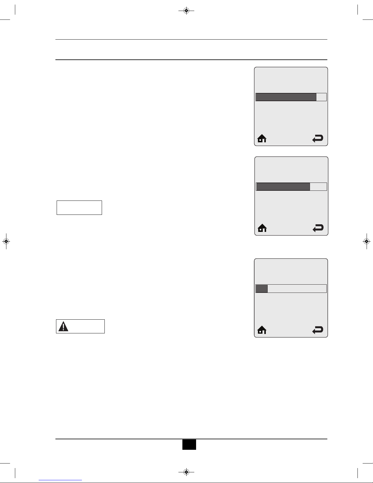
2.4 Absolute Max CH Setpoint Default: 188°F [87°C]
Absolute Max CH Setpoint can be used to prevent a user from adjusting the
central heating setpoint or outdoor reset curve above a safe operating tem-
perature in the EZ Setup Menu. A warning screen will be displayed in EZ
Setup if the user attempts to raise the setpoint above the Absolute Max CH
Setpoint. The Absolute Max CH Setpoint will be displayed on the outdoor
reset curve in EZ Setup if the user selects an outdoor reset curve which goes
above the Absolute Max CH Setpoint. Press the LEFT or RIGHT buttons
to adjust the Absolute Max CH Setpoint then press the O button to store
the setting.
2.5 CH1 Maximum Setpoint Default: 176°F [80°C]
CH1 Maximum Setpoint is the maximum setpoint for a CH1 heating call
when an Outdoor Curve option is chosen in Demand Type. CH1
Maximum Setpoint is the fixed setpoint for a CH1 heating call when a
Setpoint option is chosen in CH Demand. Press the LEFT or RIGHT
buttons to adjust the CH1 Maximum Setpoint then press the O button to
store the setting.
2.6 CH1 Minimum Setpoint Default: 80°F [27°C]
CH1 Minimum Setpoint is the minimum setpoint for a CH1 heating call
when an Outdoor Curve option is chosen in Demand Type. This setting is
not applicable when a Setpoint option is chosen in Demand Type. CH1
Minimum Setpoint must be set equal to or below the CH1 Maximum
Setpoint. Press the LEFT or RIGHT buttons to adjust the CH1 Minimum
Setpoint then press the O button to store the setting.
2.7 Outdoor Curve Coldest Day Default: 10°F [-12°C]
Outdoor Curve Coldest Day is the coldest outdoor design temperature of
the heating system when an Outdoor Curve option is chosen in Demand
Type. This setting is not applicable when a Setpoint option is chosen in
Demand Type. Press the LEFT or RIGHT buttons to adjust the Outdoor
Curve Coldest Day then press the O button to store the setting.
68ºF 188ºF
176ºF
CH1 Max.
Setpoint
60ºF 188ºF
80ºF
CH1 Min.
Setpoint
-30ºF 50ºF
10ºF
Outdoor Curve
Coldest Day
68ºF 188ºF
188ºF
Abs. Max
CH Setpoint
2015-10 restige ACVMax Control Sup 12-14-15_ACVMax_Control 12/15/15 7:36 AM age 6
7
2.0 CH Settings
2.8 Outdoor Curve Warmest Day Default: 64°F [18°C]
Outdoor Curve Warmest Day is the warmest outdoor design temperature
of the heating system when an Outdoor Curve option is chosen in
Demand Type. This setting is not applicable when a Setpoint option is
chosen in Demand Type. Press the LEFT or RIGHT buttons to adjust
the Outdoor Curve Warmest Day then press the O button to store the
setting.
2.9 CH2 Circuit Default: Enabled
CH2 Circuit allows the CH2 Maximum and Minimum Setpoints to be
enabled and disabled. When disabled, the CH2 heating call will operate
using the CH1 Maximum and Minimum Setpoints. Press the UP or
DOWN buttons to select Enabled or Disabled then press the O button
to store the setting.
•Enabled – A CH2 heating call will use CH2 Maximum and
Minimum Setpoints.
•Disabled – A CH2 heating call will use CH1 Maximum and
Minimum Setpoints.
2.10 CH2 Maximum Setpoint Default: 140°F [60°C]
CH2 Maximum Setpoint is the maximum setpoint for a CH2 heating call
when an Outdoor Reset option is chosen in CH Demand. CH2
Maximum Setpoint is the fixed setpoint for a CH2 heating call when a
Setpoint option is chosen in CH Demand. Press the LEFT or RIGHT
buttons to adjust the CH2 Maximum Setpoint then press the O button
to store the setting.
2.11 CH2 Minimum Setpoint Default: 80°F [27°C]
CH2 Minimum Setpoint is the minimum setpoint for a CH2 heating
call when an Outdoor Reset option is chosen in CH Demand. This
setting is not applicable when a Setpoint option is chosen in CH
Demand. CH2 Minimum Setpoint must be set equal to or below the
CH2 Maximum Setpoint. Press the LEFT or RIGHT buttons to
adjust the CH2 Minimum Setpoint then press the O button to store
the setting.
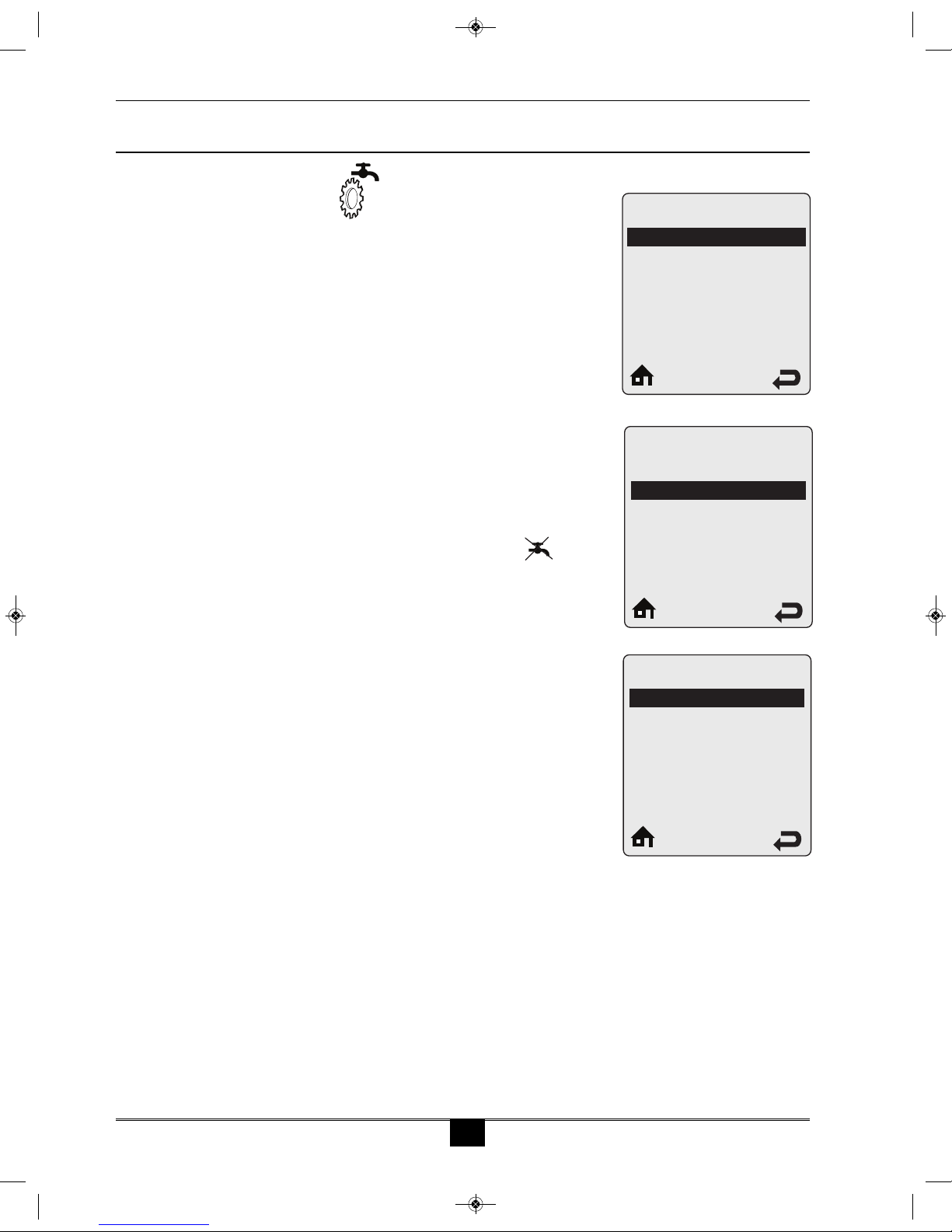
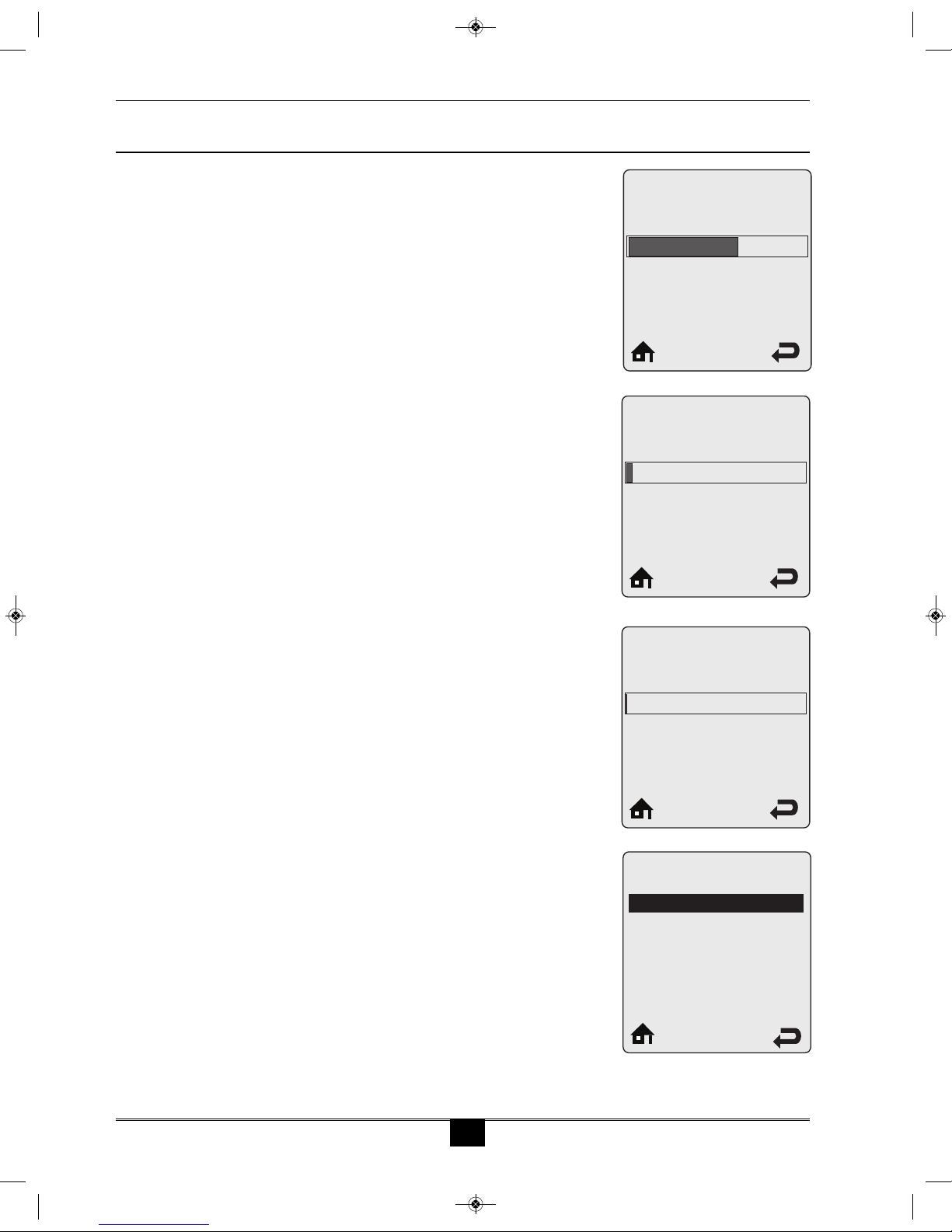
2.12 Warm Weather Shutdown Default: OFF
Warm Weather Shutdown allows the installer to enter an optional out-
door temperature at which to disable the central heating function and
any circulators placed into constant circulation with the Circulation
Pump Permanent setting. The Prestige will continue to respond to a
domestic hot water call or a 0-10V Modulation Signal when the out-
door temperature exceeds the Warm Weather Shutdown Temperature
setting. Press the LEFT or RIGHT buttons to adjust the Warm
Weather Shutdown Temperature then press the O button to store the
setting. The Warm Weather Shutdown icon is displayed on the
home screen when the outdoor temperature reaches the Warm Weather
Shutdown Temperature.
60ºF 78ºF
64ºF
Outdoor Curve
Warmest Day
CH2 / CV2 Circuit
Disabled
Enabled
Off 78ºF
Off
Warm Weather Shutdown
2015-10 restige ACVMax Control Sup 12-14-15_ACVMax_Control 12/15/15 7:36 AM age 7

8
2.0 CH Settings
2.13 Circulation Pump Permanent Default: Disabled
Circulation Pump Permanent allows the circulators configured for central
heating calls in Pump Settings to be constantly enabled even without a
central heating call. The Warm Weather Shutdown function will disable
circulators enabled via this function. A domestic hot water call will cause
the circulators to be disabled during the domestic call as long as DHW
Priority is enabled. Press the UP or DOWN buttons to select Enabled or
Disabled then press the O button to store the setting.
•Enabled – The central heating circulators will be enabled for con-
stant circulation without a central heating call.
•Disabled – The central heating circulators will only be enabled dur-
ing a central heating call.
2.14 CH Post Pump Time Default: 5 Minute
CH Post Pump Time sets how long the circulators configured for central
heating calls in Pump Settings will continue to operate at the completion
of a heating call. The CH Post Pump feature allows the heat remaining
in the boiler at the completion of a call to be sent to the heating system,
which will improve the overall efficiency of the system. Press the LEFT
or RIGHT buttons to adjust the CH Post Pump Time then press the O
button to store the setting.
2.15 Freeze Protection Default: Enabled
Freeze Protection allows the freeze protection feature to be enabled and
disabled. Press the UP or DOWN buttons to select Enabled or Disabled
then press the O button to store the setting.
•Enabled – The Freeze Protection feature is enabled to protect the
boiler from freezing. This feature monitors the boiler water tem-
perature and responds as follows when no call is present:
- 46°F [8°C] – Circulators configured to respond to a CH1 Call are
enabled.
- 42°F [6°C] – Burner operates at low fire and ciculators configured
to respond to a CH1 or CH2 Call are enabled.
- 60°F [15°C] – Freeze protection ends. Burner & all pumps turn
OFF after completing CH Post Pump Time.
•Disabled – The Freeze Protection feature is disabled.
Freeze Protection
Enabled
Disabled
Circulation Pump
Permanent
Disabled
Enabled
O 20 min
5 min
CH Post
Pump Time
2015-10 restige ACVMax Control Sup 12-14-15_ACVMax_Control 12/15/15 7:36 AM age 8

9
2.0 CH Settings
Freeze Protection should only be disabled when the system con-
tains antifreeze to prevent the system from freezing. Serious dam-
age could occur to the Prestige as well as the entire heating system
if Freeze Protection is disabled without antifreeze in the system.
The Prestige should NEVER be installed in a location where
freezing could occur. Subjecting the Prestige to freezing condi-
tions could lead to freezing of the condensate possibly causing
serious injury or death.
2.16 Frost Protection Setpoint Default: -22ºF [-30ºC]
Frost Protection will enable the circulators configured for central heating
calls in Pump Settings if the outdoor temperature falls below the Frost
Protection Setpoint and no call is present. This feature requires using the
outdoor temperature sensor and is always active and cannot be disabled.
Press the LEFT or RIGHT buttons to adjust the Frost Protection Setpoint
then press the O button to store the setting.
2.17 Parallel Shift Value Default: 0°F [0°C]
Parallel Shift allows the CH setpoint to be externally adjusted when a
Constant option is chosen in CH Demand. When a Constant option is cho-
sen in CH Demand, continuous CH1 and CH2 heating calls are generated.
Simultaneous CH1 and CH2 calls will result in the Prestige operating at the
highest CH1 or CH2 setpoint. The CH1 or CH2 Thermostat terminals with
the highest setpoint will be used to adjust the setpoint. If the Thermostat
terminals with the highest setpoint are open, the CH setpoint will decrease
by the Parallel Shift Value. If the Thermostat terminals with the highest
setpoint are closed, the CH setpoint will return to the highest CH1 or CH2
setpoint. Press the LEFT or RIGHT buttons to adjust the Parallel Shift
Value then press the O button to store the setting.
2.18 CH Call Blocking Default: 2 Minute
CH Call Blocking sets the minimum time between burner firings for
central heating calls. At the completion of a burner firing, the CH Call
Blocking time will begin. The burner will not fire again until after the
CH Call Blocking time has elapsed. The CH Call Blocking time only
prevents the burner from firing, the central heating circulators will
respond to a central heating call. This blocking time has no affect on
domestic hot water calls. The CH Call Blocking feature prevents short
cycling of the burner and extends the life of the burner components.
Press the LEFT or RIGHT buttons to adjust the CH Call Blocking
time then press the O button to store the setting.
ARNING
ARNING
-22ºF 50ºF
-22ºF
Frost Protection
Setpoint
0ºF 144ºF
0ºF
Parallel Shift Value
0 min. 30 min.
2 min.
CH Call Blocking
2015-10 restige ACVMax Control Sup 12-14-15_ACVMax_Control 12/15/15 7:36 AM age 9
10
Demand Type
Thermostat
Sensor
3.0 DHW Settings
3.1 Navigation:
Home Screen>Installer Menu>CH & DHW Settings>DHW Settings
The DHW Settings menu contains settings related to domestic hot
water operation. Each line contains a DHW Setting followed by its cur-
rent value. Six DHW Settings are displayed on the screen at one time.
Press the UP or DOWN buttons to scroll through additional DHW
Settings.
3.2 DHW Operation Default: Enabled
DHW Operation allows the domestic hot water function to be enabled
and disabled. Press the UP or DOWN buttons to select Enabled or
Disabled then press the O button to store the setting.
•Enabled - The Prestige will respond to a domestic hot water call.
•Disabled - The Prestige will not respond to a domestic hot water
call. The domestic hot water operation disabled icon is dis-
played on the home screen when domestic hot water operation has
been disabled.
3.3 Demand PRESTIGE Solo Default: Thermostat
PRESTIGE Excellence Default: Sensor
Demand Type allows the installer to select the type of device which will
generate a domestic hot water call. Press the UP or DOWN buttons to
select the DHW Demand Type then press the O button to store the set-
ting. The DHW Demand options are:
•Thermostat - A domestic hot water call from an aquastat or dry
contact switch will enable the Prestige with a fixed setpoint for a
domestic hot water call.
•Sensor - This option requires the use of Indirect Water Heater
Sensor PSRKIT22 which is included with every PRESTIGE Solo.
The PRESTIGE Excellence utilizes an Indirect Water Heater
Sensor. The Prestige will monitor the DHW storage temperature
and generate a domestic hot water call when the temperature drops
below the DHW Setpoint - DHW On Differential.
3.0 DHW SETTINGS
DHW Settings
DHW Operation
Demand
DHWBoiler Setpoint
DHW Setpoint
DHW On Dierential
DHW Storage Adder
Enabled
Thermostat
186ºF
140ºF
6ºF
46ºF
DHW Operation
Disabled
Enabled
2015-10 restige ACVMax Control Sup 12-14-15_ACVMax_Control 12/15/15 7:36 AM age 10
11
3.4 DHW Boiler Setpoint Default: 168ºF [76ºC]
DHW Boiler Setpoint is the fixed boiler setpoint temperature during a
domestic hot water call when the Thermostat option is chosen in DHW
Demand. Press the LEFT or RIGHT buttons to adjust the DHW Boiler
Setpoint then press the O button to store the setting.
3.5 DHW Setpoint Default: 140°F [60°C]
DHW Setpoint is the domestic hot water storage setpoint temperature
when the Sensor option is chosen in DHW Demand. Press the LEFT or
RIGHT buttons to adjust the DHW Setpoint then press the O button to
store the setting.
The boiler setpoint is automatically set to the DHW Setpoint +
DHW Storage Adder when the Sensor option is chosen in DHW
Demand. The boiler setpoint is limited to 194°F [90°C].
3.6 DHW On Differential Default: 6°F [3°C]
DHW On Differential sets how far the DHW storage temperature must fall
below the DHW Setpoint to create a domestic hot water call when the
Sensor option is chosen in DHW Demand. The domestic hot water call
will end when the DHW storage temperature rises above the DHW
Setpoint. Press the LEFT or RIGHT buttons to adjust the DHW On
Differential then press the O button to store the setting.
The DHW On Differential setting greatly affects the production
of domestic hot water. A low setting could result in a rapid
response to a domestic hot water call resulting in a potential
scald hazard. It is strongly recommended that the installer uti-
lize a thermostatic mixing valve on the hot water outlet of the
Indirect Water Heater. Failure to comply could result in severe
personal injury, death, or substantial property damage.
NOTICE
DANGER
3.0 DHW Settings
96ºF 188ºF
168ºF
DHW
Boiler Setpoint
4ºF 18ºF
6ºF
DHW On Dierential
68ºF 176ºF
140ºF
DHW Setpoint
2015-10 restige ACVMax Control Sup 12-14-15_ACVMax_Control 12/15/15 7:36 AM age 11
12
DHW Priority
Enabled
Disabled
3.0 DHW Settings
3.7 DHW Storage Adder Default: 46°F [25°C]
DHW Storage Adder is used to compute the boiler setpoint when the
Sensor option is chosen in DHW Demand. The boiler setpoint will be
DHW Setpoint + DHW Storage Adder for a domestic hot water call.
Press the LEFT or RIGHT buttons to adjust the DHW Storage Adder
then press the O button to store the setting.
3.8 DHW Post Pump Time Default: 2 Minute
DHW Post Pump Time sets how long the circulators configured for
domestic hot water calls in Pump Settings will continue to operate at the
completion of a domestic hot water call. The DHW Post Pump feature
allows the heat remaining in the boiler at the completion of a call to be
sent to the Indirect Water Heater, which will improve the overall effi-
ciency of the system. Press the LEFT or RIGHT buttons to adjust the
DHW Post Pump Time then press the O button to store the setting.
3.9 DHW Priority Timeout Default: Off
DHW Priority Timeout allows the installer to enter an optional time limit
that a domestic hot water call has priority over a central heating call when
DHW Priority is set to Enabled. Press the LEFT or RIGHT buttons to
adjust the DHW Priority Timeout then press the O button to store the
setting.
3.10 DHW Priority Default: Enabled
DHW Priority allows the domestic hot water priority function to be
enabled and disabled. Press the UP or DOWN buttons to select Enabled
or Disabled then press the O button to store the setting.
•Enabled- Domestic hot water calls will have priority over a central
heating call. The boiler setpoint will be set to the domestic hot
water setpoint during a domestic hot water call. The DHW circu-
lator will be enabled and the heating circulators will be disabled
during a domestic hot water call.
•Disabled - Domestic hot water calls will not have priority over a
central heating call. The boiler setpoint will be set to the domestic
hot water setpoint when only a domestic hot water call is present.
The boiler setpoint will be set to the highest setpoint when simul-
10ºF 54ºF
28ºF
DHW
Storage Adder
O 30 min.
2 min.
DHW
Post Pump Time
O 120 min.
O
DHW Priority Timeout
2015-10 restige ACVMax Control Sup 12-14-15_ACVMax_Control 12/15/15 7:36 AM age 12

13
3.0 DHW Settings
taneous domestic hot water and central heating calls are present. The
DHW circulator will be enabled during a domestic hot water call.
The heating circulators will be enabled during a central heating call.
Simultaneous domestic hot water and central heating calls will
result in the PRESTIGE operating at the highest target temper-
ature when DHW Priority is set to Disabled. The use of a mixing
device on the lower temperature zones may be required to pro-
tect the lower temperature zones from damage.
DHW Priority should only be set to Disabled when Prestige
Model is set to Solo. Setting DHW Priority to Disabled when
Prestige Model is set to Excellence will not disable DHW
Priority.
3.11 DHW Call Blocking Default: 0 Minute
DHW Call Blocking sets the minimum time between burner firings for
domestic hot water calls. At the completion of a burner firing, the DHW
Call Blocking time will begin. The burner will not fire again until after the
DHW Call Blocking time has elapsed. The DHW Call Blocking time only
prevents the burner from firing, the circulators configured for domestic hot
water calls in Pump Settings will respond to a domestic hot water call.
This blocking time has no affect on central heating calls. The DHW Call
Blocking feature prevents short cycling of the burner and extends the life
of the burner components. Press the LEFT or RIGHT buttons to adjust
the DHW Call Blocking time then press the O button to store the setting.
3.12 DHW To CH Call Blocking Default: 1 Minute
DHW To CH Call Blocking sets the minimum time between a DHW burn-
er firing and a CH burner firing. At the completion of a DHW burner fir-
ing, the DHW to CH Call Blocking time will begin. The burner will not
fire again for a central heating call until after the DHW To CH Call
Blocking time has elapsed. The DHW To CH Call Blocking time only pre-
vents the burner from firing, the circulators configured for central heating
calls in Pump Settings will respond to a central heating call. This blocking
time has no affect on domestic hot water calls. The DHW To CH Call
Blocking feature prevents the burner from firing when switching from a
domestic hot water call to a central heating call. This allows the remaining
heat in the heat exchanger to be dissipated and potentially satisfy the cen-
tral heating call. Press the LEFT or RIGHT buttons to adjust the DHW
To CH Call Blocking time then press the O button to store the setting.
NOTICE
ARNING
0 min. 30 min.
0 min.
DHW Call
Blocking
0 min. 30 min.
1 min.
DHW to CH
Call Blocking
2015-10 restige ACVMax Control Sup 12-14-15_ACVMax_Control 12/15/15 7:36 AM age 13

14
3.0 DHW Settings
3.13 Antilegionella Function Default: Enabled
The Antilegionella Function ensures that an Indirect Water Heater is heat-
ed at least once per week to prevent the growth of Legionella bacteria.
Press the UP or DOWN buttons to select Enabled or Disabled then press
the O button to store the setting.
•Enabled- When the Thermostat option is chosen in DHW Demand,
a domestic hot water call is generated for 15 minutes once per week
to heat the Indirect Water Heater. When the Sensor option is cho-
sen in DHW Demand, a domestic hot water call is generated until
the DHW storage temperature reaches 140°F [60°C] once per
week. When the Sensor option is chosen in DHW Demand, the
weekly timer is reset whenever the DHW storage temperature
reaches 140°F [60°C] to prevent unnecessary firings. This function
will be active even if DHW Operation has been set to Disabled.
•Disabled - The Prestige will only fire in DHW mode when a
domestic hot water call is received.
The Antilegionella Function should only be left enabled when
an Indirect Water Heater is installed. Enabling the
Antilegionella Function without an Indirect Water Heater will
result in the Prestige firing once per week in DHW mode. This
could cause a Manual Reset Hard Lockout resulting in sub-
stantial property damage.
The Antilegionella Function is most effective when the Sensor
option is chosen in DHW Demand. The use of an Indirect
Water Heater Sensor ensures that the domestic hot water is
heated to 140°F [60°C] at least once per week.
ARNING
BEST PRACTICE
Antilegionella Function
Enabled
Disabled
2015-10 restige ACVMax Control Sup 12-14-15_ACVMax_Control 12/15/15 7:36 AM age 14

15
4.1 Navigation:
Home Screen>Installer Menu>CH & DHW Settings>Boiler Settings
The Boiler Settings menu contains settings related to general boiler
operation. Each line contains a Boiler Setting followed by its current
value.
4.2 Prestige Model PRESTIGE Solo Default: Solo (2 pumps)
PRESTIGE Excellence Default: Solo/Excel. 3 way valve
Prestige Model selects between Solo with pump operation and
Excellence with 3-way diverter valve operation. Press the UP or DOWN
buttons to select Solo (2 pumps) or Solo/Excel. 3 way valve then press
the O button to store the setting.
•Solo (2 pumps) - A CH Demand is satisfied using the circulators
configured for central heating calls in Pump Settings. A DHW
Demand is satisfied using the circulators configured for domestic
hot water calls in Pump Settings.
•Solo/Excel. 3 way valve - CH and DHW Demands are satisfied by
the built-in circulator and 3 way diverter valve.
Excellence units also require setting Demand Type to Sensor for
correct DHW operation.
4.3 Lockout Temp. Default: 210°F [99°C]
Lockout Temp. allows the High Boiler Temperature lockout (E3) to be
temporarily adjusted down to 102°F [39°C] for inspector demonstra-
tion. Press the UP or DOWN buttons to select 210°F [99°C] or 102°F
[39°C] then press the OK button to store the setting.
•102°F [39°C] – A High Boiler Temperature lockout (E3) will occur
when the boiler temperature reaches 102°F [39°C].
•210°F [99°C] – A High Boiler Temperature lockout (E3) will occur
when the boiler temperature reaches 210°F [99°C].
NOTICE
4.0 Boiler Settings
Prestige Model
Solo (2 pumps)
Solo/Excel. 3 way valve
Boiler Settings
Prestige Model
LockoutTemp.
ModbusAddress
Pump Settings
IgnitionLevel NAT
Solo (2 pumps)
210ºF [99ºC]
0=BCST
3000rpm
Lockout Temp.
102ºF [39ºC]
210ºF [99ºC]
4.0 BOILER SETTINGS
2015-10 restige ACVMax Control Sup 12-14-15_ACVMax_Control 12/15/15 7:36 AM age 15

16
4.0 Boiler Settings
4.4 Modbus Address Default:0=BCST
Modbus Address assigns the boiler with a unique address in the Modbus
control system. Press the LEFT or RIGHT buttons to change the
Modbus Address then press the O button to store the setting. See Pages
57 & 58 for Modbus Interface information.
4.5 Pump Settings
Pump Settings allows the selection or assigment of the appropriate
pump configuration for the installation piping arrangement. The cur-
rent pump configuration will be displayed in the first line. There are
numerous preset configurations to select from and a flexible configu-
ration mode.
4.5.1 Current Pump Configuration
Current Pump Configuration displays the selected pump configuration
or indicates that there is a custom pump configuration used by display-
ing “Modified.”
4.5.2 Preset Pump Configuration Prestige Model: Solo
Preset Pump Configuration will display thirteen options (Config 1 -
Config 13) that correspond to specific hydraulic schemes. Please refer
to Figs. 2 through 14 on pages 18-30. Press the UP or DOWN buttons
to scroll through the options then press the O button to store the set-
ting.
4.5.3 Preset Pump Configuration Prestige Model: Excellence
Preset Pump Configuration will display four options (Solo/Excellence
1 - Solo/Excellence 4) that correspond to specific hydraulic schemes.
Please refer to Figs. 15 through 18 on pages 31-34. Press the UP or
DOWN buttons to scroll through the options then press the O button
to store the setting.
4.5.4 Flexible Pump Configuration
Flexible Pump Configuration allows the installer to customize the flex-
ible relays to a specific installation arrangement that is not addressed in
the Preset Pump Configuration options. There are a total of six
Flexible Relays and an Error Relay setting that must be set.
0=BCST 247
0=BCST
Modbus Address
Pump Settings
Current Pump Cong
Preset Pump Cong
Flexible Pump Cong
Modied
Flexible Pump Cong
Flex. Relay 1 (CH)
Flex. Relay 2 (DHW)
Flex. Relay 3 (P3)
Flex. Relay 4 (ERR)
Flex. Relay 5 (Flame)
Flex. Relay 6 (P4)
2015-10 restige ACVMax Control Sup 12-14-15_ACVMax_Control 12/15/15 7:36 AM age 16
Table of contents
Other ACV Controllers manuals


Popular Controllers manuals by other brands

National Instruments
National Instruments sbRIO-9607 user manual

HomeMatic
HomeMatic HM-Sec-SFA-SM Installation and operating manual

ABB
ABB MS132 installation instructions

Hitachi
Hitachi EH-150 Type I Applications manual

Martin Audio
Martin Audio MICT3B - 7-1996 manual

Philio Technology Corporation
Philio Technology Corporation PAN34 manual

Binks
Binks 85-441 Assembly manual

Aimco
Aimco ArcaDyne IEC4W Operator's manual

Franklin Electric
Franklin Electric SmartStart SSP3E-30S owner's manual

Corbin Russwin
Corbin Russwin ASSA ABLOY WM800 installation instructions

DOLD
DOLD Safemaster Pro user manual

YASKAWA
YASKAWA MP2000 Series troubleshooting manual


