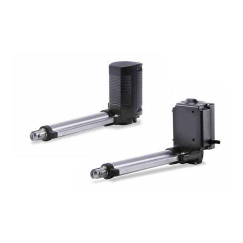
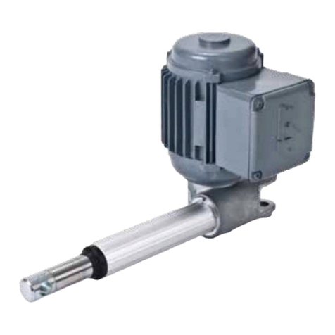
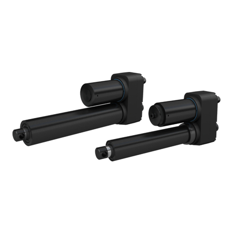
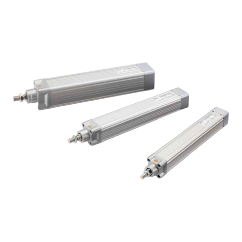
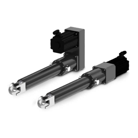
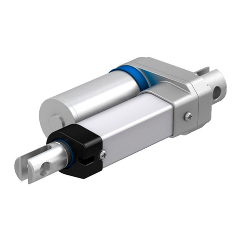
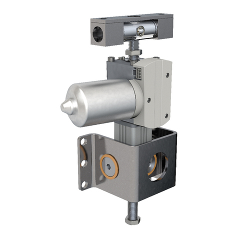
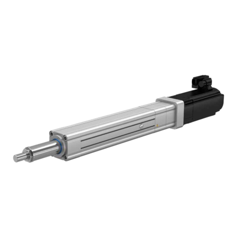
Ewellix CAHB-2E Series User manual

CATEGORY
MAX 2 LINESINSTALLATION, OPERATION AND MAINTENANCE MANUAL
CAHB-2xE series
Linear actuator CAHB-20E, CAHB-21E and CAHB-22E


33
Contents
1.0 General information ...................................................4
1.1 Information on this manual ..........................................4
1.2 Explanation of symbols and signal words ...................4
1.3 Limitation of liability .....................................................5
1.4 Warranty terms.............................................................5
1.5 Customer service .........................................................5
2.0 Safety ...........................................................................6
2.1 Limitation of liability .....................................................6
2.1.1 Intende d use ............................................................6
2.2 Responsibility of the owner and processor.................6
2.2.1 Qualications ...........................................................7
2.2.2 Specicdangers......................................................7
2.3 Safety equipment .........................................................7
2.4 Changesandmodicationsontheactuator ...............8
3.0 Technical data.............................................................9
3.1 Operating conditions....................................................9
3.2 Operating voltages and limits ......................................9
3.3 Product label .............................................................. 10
4.0 Structure and function............................................. 11
4.1 O ve r vi ew ..................................................................... 11
4.2 Brief description ......................................................... 13
4.3 Special features.......................................................... 13
4.4 Construction group description ................................ 14
4.5 Connection ................................................................. 14
4.6 Options ....................................................................... 14
4.6.1 Limit switch ............................................................ 14
4.6.2 Potentiometer......................................................... 14
4.6.3 Absolute analog position output ........................... 15
4.6.4 Encoder.................................................................. 15
4.6.5 Manual Override..................................................... 15
5.0 Transport, packaging and storage.........................16
5.1 Safety information for the transport........................... 16
5.1.1 Transport inspection.............................................. 16
5.1.2 Return to the manufacturer.................................... 16
5.1.3 Packaging .............................................................. 16
5.2 Storage ....................................................................... 16
6.0 Installationandrstoperation ............................... 17
6.1 Installation location .................................................... 17
6.2 Installation .................................................................. 17
6.3 Inspectionspriortorstoperation............................. 19
6.4 Connect to power supply........................................... 19
6.4.1 Wiring scheme: ...................................................... 19
6.4.2 DenemovingdirectionVSpower“+”,”-” ............. 19
7.0 Operation...................................................................20
7.1 Safety..........................................................................20
7.2 Action before operation ............................................. 20
7.3 Action during operation..............................................20
7.3.1 Normal operation ...................................................20
7.4 Disengagement in case of emergency ...................... 21
7.5 Action after use .......................................................... 21
8.0 Maintenance..............................................................22
8.1 Spare parts.................................................................22
8.2 Maintenance plan.......................................................22
8.3 Maintenance work......................................................23
8.3.1 Cleaning .................................................................23
8.3.2 Inspections and readings ......................................23
8.3.3 Check of visual condition ......................................23
8.4 Measures after completed maintenance ...................23
9.0 Malfunctions .............................................................24
9.1 Malfunction table........................................................25
9.2 Startofoperationafterxingmalfunction.................25
10.0 Dismantling ...............................................................26
10.1 Dismantling.................................................................26
10.1.1 DismantlingofCAHB-20series.............................26
10.2 Disposal......................................................................26
11.0 Appendix....................................................................27
WARNING
Readthismanualbeforeinstalling,operatingormaintainingthis
actuator. Failure to follow safety precautions and instructions could
causeactuatorfailureandresultinseriousinjury,deathorproperty
damage.

4
CAHB-20 series
1.0 General information
1.1 Information on this
manual
This manual provides important information on how to work
withtheactuatorsafelyandeciently.
Themanualispartoftheactuator,mustalwaysbekeptin
the actuator’s direct proximity and should be available for
the personnel at any time. All personnel working with the ac-
tuator must read and understand this manual before starting
anywork.Strictcompliancewithallspeciedsafetynotes
and instructions is a basic requirement for safety at work.
Moreover,theaccidentpreventionguidelinesandgeneral
safety precautions applicable at the place of use of the actu-
ator must also be complied with.
Forbetterrepresentationofcircumstances,theillustrations
used are not necessarily to scale and may vary from the ac-
tual design of the actuator.
1.2 Explanation of
symbols and signal words
Safety precautions
Safetyprecautionsareidentiedbysymbolsandsignal
words. These signal words indicate the severity of the
hazard.
Adhere to these safety precautions and act cautiously in or-
dertoavoidaccidents,personalinjuriesanddamageto
property.
DANGER
Indicatesadangeroussituation,which
will lead to death or serious personal
injury,iftheprecautionarymeasuresare
ignored.
WARNING
Indicatesadangeroussituation,which
can lead to minor or moderate injury or
propertydamage,iftheprecautionary
measures are ignored.
CAUTION
Indicatesadangeroussituation,which
can lead to minor or moderate injury
the precautionary measures are ignored.
NOTE
Emphasizes useful hints and
recommendations as well as information
forecientandtrouble-freeoperation.

5
1.0 General information
1.3 Limitation of liability
All information and notes in this manual were compiled un-
derdueconsiderationofvalidstandardsandregulations,the
present status of technology and our years of knowledge
and experience.
The manufacturer will not be liable for damage resulting
from:
• disregarding this manual
• unintended use
• employment of untrained personnel
• unauthorized conversions
• technicalmodications
• manipulation or removal of the screws on the actuator
• use of unapproved spare parts
Incasetheactuatoriscustomised,theactualproductdeliv-
eredmaybedierentfromwhatisdescribedinthemanual.
Inthiscase,askEwellixforanyadditionalinstructionsor
safety precautions relevant to these actuators.
Wereservetherighttomaketechnicalmodicationstothe
actuator to improve usability.
1.4 Warranty terms
Theapplicableandeectivewarrantytermsarethosecon-
tained in the manufacturer’s terms and conditions of sale.
1.5 Customer service
Ewellix Customer Service is always available to provide tech-
nical information and answer questions.
The contact information for Ewellix Customer Service can be
found on www.ewellix.com.

6
CAHB-20 series
6
2.0 Safety
2.1 Limitation of liability
This chapter provides an overview of important safety pre-
cautions and information necessary for safe and trou-
ble-freeinstallation,operationandmaintenance.
DisregardingthisManualandsafetyprecautionsspecied
therein may result in considerable danger and possible seri-
ous injury or death.
2.1.1 Intended use
The actuator has been designed and built exclusively for its
intended purpose as described in these instructions.
WARNING
Risk from misuse!
Any utilization of this actuator beyond its intended purpose may
lead to potentially hazardous situations.
Therefore:
• Strictly adhere to all safety precautions and instructions in this
manual.
• Donotallowthisactuatortobesubjectedtoweatherconditions,
strongUVrays,corrosiveorexplosiveairmediaaswellasother
aggressive media.
• Donotmodify,retoolorchangethestructuraldesignorindividual
components of the actuator.
• Never use the actuator outside of the technical application and
operational limits.
Anyinjury,damageorlosscausedbyviolationofthesein-
structions will be the responsibility of the customer.
2.2 Responsibility of the
owner and processor
The actuator is designed for personal use and is also used
in commercial applications by owner or processors.
The processor is the contracting partner of the reseller or
the manufacturer. The processor installs the actuator in a
complete system (application).
The owner of the system is therefore subject to require-
ments of the Occupational Health and Safety Act.
InadditiontothesafetyinstructionsinthisManual,the
owner or processor must do the following concerning these
safetyandacci-dentpreventionguidelinesandenvironmen-
tal precautions regulations applicable to the site of the sys-
tem’s installation:
• Inform themselves of applicable industrial safety precau-
tions and determine additional hazards that arise due to
thespecicworkingconditionsprevailingatthesitewhere
the actuator is installed using risk assessment. The risk
assessment must be implemented in the form of work in-
structions for the actuator operation.
• Conrmthattheworkinstructionscreatedforthesystem
including the actuator satisfy current legal requirements
and must alter the instructions if they don’t.
• Clearly regulate and specify the responsibilities for instal-
lation,operation,maintenance,andcleaning.
• Ensure that all employees who deal with the actuator have
read and understood this Manual.
• Provide personnel with the required protective equipment.
Inaddition,ownermusttrainpersonnelatregularintervals
and inform personnel of the hazards.
Inaddition,ownerorprocessorsmustensurethattheactua-
tor is in an adequate working condition. They must do the
following:
• Ensure that the maintenance intervals described in these
instructions are complied with.
• Have all safety devices inspected regularly for function and
completeness.
WARNING
Risk from misuse!
AnImproperinstallation,operationandmaintenancecanresultin
seriousinjury,deathorpropertydamage.
Useonlyqualified,instructed,ortrainedpersonnel(asdescribed
below)whohaveread,understandandfollowtheseinstructions.

7
2.0 Safety
7
2.2.1 Qualications
Thefollowingqualicationsarespeciedfordierentareas
of activity listed in the Manual.
• An instructed person (Operator)
has been instructed by the customer in an orientation ses-
sion on the assigned tasks and possible dangers in case of
improper behaviour.
• Qualiedpersonnel
basedontheirprofessionaltraining,know-howandexperi-
ence as well as knowledge of the applicable standards and
regulations is able to perform assigned work activities and
to detect and avoid possible dangers on their own.
• A professional electrician
basedonhis/herprofessionaltraining,know-howandex-
perience as well as knowledge of the applicable standards
and regulations is able to perform work on electrical sys-
tems and to detect and avoid possible dangers on his/her
own. The professional electrician has been trained for the
special location where he/she works and knows the rele-
vant standards and regulations.
Only persons who are expected to perform their tasks reli-
ably are permitted as personnel. Persons whose reaction
capabilityisimpaired,e.g.throughdrugs,alcoholormedi-
cation,arenotpermitted.
2.2.2 Specic dangers
The following section lists the residual risks that have been
determined by the risk assessment.
• Heedthesafetyinstructionslistedhere,andthewarnings
insubsequentchaptersofthisManual,toreducehealth
hazards and to avoid dangerous situations.
DANGER
Danger to life caused by electric current!
Touching conductive parts causes a direct danger to life. Damage
to insulation or individual components can cause danger to life.
Therefore:
• Intheeventofdamagetoinsulation,switchothepowersupply
immediately and have the parts repaired.
• Work on the electrical system must be carried out only by profes-
sional electricians.
• De-energizethemachineforallworkontheelectricalsystem.
• Beforemaintenance,cleaningorrepairwork,switchothepower
supply and perform lockout procedures so it cannot be turned on
again.
• Donotbridgefusesormakethemineective.Whenchanging
fuses,makesureyouusethecorrectamperage.
• Keepmoistureawayfromconductiveparts.Ifyoudon’t,thiscan
cause short circuit.
WARNING
Danger of injury caused by moving components!
Rotating and/or linearly moving components can cause severe injury.
Therefore:
• Donotworkonorplaceanyofyourbody,hands,orarmsnear
moving components.
2.3 Safety equipment
WARNING
Danger due to malfunctioning safety equipment!
Forsafeoperation,besureallsafetyequipmentisingoodworking
order.
Therefore:
• Always check functionality of safety equipment according to the
maintenance plan.
• Never disengage safety equipment.
• Safetyequipmentmayneverbeby-passedormodied.
Integration in an emergency-stop system
required (for certain applications)
The actuator is only intended for installation into an an appli-
cation or system. It does not have its own operating control
elements and does not have an independent
emergency-stop-function.
Installtheactuatorsothatitispartofanemergencyshut-o
system and can be stopped if necessary.
Theemergencyshut-osystemhastobeconnectedinsuch
a way that a disruption of the power supply or the reactiva-
tion of the power supply after a power disruption cannot
cause a hazardous situation for persons and objects.
Theemergencyshut-osystemsmustalwaysbefreelyac-
cessible.
NOTE
The processor decides which applications require the
installationofanemergencyshut-offsystem.

8
CAHB-20 series
The following safety features may have been
installed:
A thermal switch is integrated into the motor inside to pre-
vent damage from overheating. If overheating occurs when
theactuatorisoperating(overspecication),theswitch
wouldbeactivated,thepowerwouldbecut-o;afterthe
temperaturefallsbelowthethreshold,theswitchwillrestore.
CAUTION
Topreventdamagefromoverheating,donottrytooperate
actuator until its temperature has fallen below the threshold for
the switch to operate.
A driving screw nut converts the rotation of the gear unit into
linear motion. If an overload occurs when the actuator is
operating,aballdetentclutchwilloperate,thusstoppinglin-
ear motion.
CAUTION
Continued operation of the clutch can result in overheating and
damagetothelinearactuator.Ifclutchactivates,switchoffpower
immediately.
2.4 Changes and
modications on the
actuator
To avoid hazardous situations and to ensure optimal perfor-
mance,donotmakeanychangesormodicationstotheac-
tuatorunlesstheyhavebeenspecicallyauthorizedby
Ewellix.

9
3.0 Technical data
9
NOTE
Thetechnicaldata(dimensions,weight,output,connectionvalues
etc.) can be found in the enclosed drawings and data sheets (⮑11
Appendix, page 27).
3.1 Operating conditions
Environment
Information Value Unit
Temperature range –40to+85 °C
Relativeatmospherichumidity,
maximum (no build up of condensation) up to 96 %
NOTE
• Full performance: 0 ~ 40 °C
• Degradedperformance:below0°C,above40°C.(Theloadca-
pacityandspeedwoulddegraded,thecurrentwouldrise,can
contact Ewellix for more information).
24 V DC & 48 V DC version – Duration (intermittent)
Information Value Unit
Maximum operating time without a break 1Cycles
Break until next operation 4
Times of
operating
time
Maxdutycycleatratedload:20%(85son/340so)
12 V DC version – Duration (intermittent)
Information Value Unit
Maximum operating time without a break 1Cycles
Break until next operation 9
Times of
operating
time
Maxdutycycleatratedload:10%(85son/765so)
3.0 Technical data
3.2 Operating voltages
and limits
Theoperatingvoltagesandthelimitsforstandardversion,
including when PWM is used for speed ramp up refer to:
12 V DC version: supply voltage
• Foractuator:12VDC±20%
• ForEncoder:4-20VDC
• ForPotentiometer:Voltagelimitedbypower2W
• Forabsoluteanalogpositionsensor:10~55VDC(current
consumption 15 mA max.)
24 V DC version: supply voltage
• Foractuator:24VDC±10%
• Encoderoption:4–20VDC
• Potentiometeroption:Voltagelimitedbypower2W
• Forabsoluteanalogpositionsensor:10~55VDC(current
consumption 15 mA max.)
48 V DC version: supply voltage
• Foractuator:40~55VDC
• Encoderoption:4–20VDC
• Potentiometeroption:Voltagelimitedbypower2W
• Forabsoluteanalogpositionsensor:10~55VDC(current
consumption 15 mA max.)

10
CAHB-20 series
10
3.3 Product label
CAHB-2X-XXE-XXXXXXX-BXXXXX-XXX
XX VDC, XX A, XXX N (pull/push), XXX mm/s
Duty cycle XX% (85s on / XXXs off)
Serial No.
YYYYMMDDXXXX
IP66M / IP69K
Ewellix Motion Technologies (Pinghu) Co., Ltd.
Customer No. N/A or XXXXXX
1
2
3
4
5
6
7
8
9
10
Fig. 1
The product label provides the following information
1. Identicationofactuator(typekey)
2. Part number
3. Customer part number
4. Performance(powervoltage,ratedcurrent,ratedload,
speed with rated load)
5. Duty cycle
6. Serial number
7. IP level
8. Manufacturer or the country of origin
9. CE mark
10. RoHS mark

11
4.0 Structure and function
4.1 Overview
CAHB- 20 E
Include 3 types outline.
4.0 Structure and function
Fig. 2
CAHB-20 E without feedback
1. Front hinge head
2. Push tube
3. Guiding tube (Steel tube)
4. Motor
5. Cable
6. Rear hinge head
7. Gearbox
Fig. 3
CAHB-20 E with feedback
8. Middle housing
Fig. 4
CAHB-20 E with manual override (Manual
override option can be congured on all series)
9. Manual override part
47
12 3
6
8
9
5

12
CAHB-20 series
Fig. 5
CAHB-21 E and 22 E without feedback
1. Front hinge head
2. Push tube
3. Guiding tube (Al alloy tube)
4. Motor
5. Cable
6. Rear hinge head
7. Gearbox
Fig. 6
CAHB-21 E and 22 E
Include 3 types outline.
CAHB-21 E and 22 E with feedback
8. Middle housing
Fig. 7
CAHB-21 E and 22 E with manual override
(Manual override option can be congured on all
series)
9. Manual override part
4
7
12 3
6
5
8
9

13
4.0 Structure and function
4.2 Brief description
Overview
This actuator is to be used exclusively for installation into a
dynamiccentric-compressionortensile-loadedlift.
The linear actuator consists of a motor part (4),agearunit
(7) and a linear unit (3),connectedwitheachotherbyabay-
onet joint.
The actuator consists of a direct current motor with helical
gearwhichsetsinmotionageartransmissionsystem.Via
thedrivingscrewandnut,therotationofgearistransformed
into a linear motion of the actuator.
The front hinge head (1) and the rear hinge head (6) transmit
the actuator power to both sides of the application.
Fig. 8
4.3 Special features
Mechanical overload protection
The actuator contains a mechanical overload protection unit
(clutch).This overload protection unit will activate if the linear
unit of the actuator overloads. This activation will avoid to
pushorpulloverthemaximumforcedenedonthedata-
sheet and will protect the motor and gear unit from being
damaged.
CAUTION
Continued operation of the clutch can result in overheating and
damagetothelinearactuator.Ifclutchactivates,switchoffpower
immediately.
Thermal protection
Thethermalswitchbuilt-inthemotorwillswitchothe
power of the motor in case of over heat of the motor. It will
automatically reset when the temperature decreases.
Overload or more frequent operating the actuator over the
maxdutycyclesdenedonthedatasheetwouldleadto
motor overheating.
CAUTION
To prevent damage from overheating when the actuator stop with a
highmotortemperature,donotrestarttheactuatorbutwaituntilthe
temperature decreases.
Gore automotive vent
The vent allows the equalization of the pressure inside the
actuatorwhenitisoperated,thatwillinsureanoptimumus-
age of the sealing system
Fig. 9
0°
03°
06°
09°
120°
150°
0°
03°
06°
09°
120°
150°

14
CAHB-20 series
4.4 Construction group
description
Motor
ThemotorisabrushedDCmotor,12or24VDC.Themo-
tor’s shaft is connected to a helical gear. The lift speed de-
pends on the load. The motor unit is surrounded by metal
housingandequippedbyaEMClter.Themetalhousing
cannot be opened.
Gear unit
The helical gear is directly powered by the motor shaft. Gear
unit is connected to the over load clutch that moves the drive
screw system.
Linear unit
The linear unit is surrounded and protected by the guiding
tube.ThelinearunitoftheCAHB-21EorCAHB-22Eis
equipped by brake. The push tube of the actuator is con-
nected to the nut of the drive screw unit and aligned by the
guiding tube.
4.5 Connection
Fig. 10
1
CAHB-2… connections
1. Wires to connect actuator to power supply or to an exter-
nal control.
4.6 Options
Ifnotspeciedotherwise,theoptionslistedbelowareavail-
ablefortheentireseriesofCAHB-2…linearactuators.
4.6.1 Limit switch
The limit switch makes it possible to control the stroke of the
linear unit by internal setting. Contact the Ewellix to adjust
the setting of limit switch.
Remark:LimitswitchisnotavailableforCAHB-20
4.6.2 Potentiometer
The potentiometer provides a signal indicating the position
ofthelinearactuator.Theelectricalspecicationasonthe
datasheet.
• Linear actuator with potentiometer unit: colours of wire are
white,greenandbrown(⮑Fig.11).
Retract Extend
Green
Brown
White
POT
Limit + POT:
White
Green Brown
0 CW 10K
Fig. 11
Potentiometer

15
4.0 Structure and function
4.6.3 Absolute analog position output
Theabsoluteanalogpositionsensorisamultitudenon-con-
tact magnetic sensor. It provides a signal indicating the posi-
tionofthelinearactuator.theoutputsignalis0~5VDCvolt-
age(currentoutput5mAmax).Theelectricalspecication
andresolutionrefertodatesheet,thewiresconnectingrefer
to 6.4.1 Wiring scheme.
output(V)
5
4,5
0,5
0
resolution
tan(α)=outputrelationto
displacement(V/mm)
α
displacement (mm)
NOTE
WhenactuatorwithPOTortheanalogoutput,don’trotatethepush
tube 45 degree and don’t connect to power before the actuator is
installed into device (see picture below) Otherwise would demage
the potentiometer or the analog sensor components.
WARNING
4.6.4 Encoder
Dual hall sensor for incremental position feedback. It outputs
signals when the actuator is moving outwards and inwards
respectively.Theoutputsignals,channel1and2,are±90°,
seethegurebelow.Theelectricalspecicationasonthe
data sheet.
The supply voltage to the encoder must be in the range 4 to
20VDC)
Encoder
Hall 1
Hall 2
Hall 1
Hall 2
Signal CCW extension
Signal CW retraction
4.6.5 Manual Override
Manual override option provides a solution to move the push
tube manually and without tool when power failure. The un-
screwed cover can be used as a hand crank. Also a power
tool can be used to drive the cover by the hexagon head.
Please stop operating the override device when the clutch is
activated.
Thestructureandoperatinginstructionseethegurebelow.
R
e
t
r
a
c
t
i
o
n
E
x
t
e
n
s
i
o
n
Release the motor cover (1). Use the slot (2) to
rotate the motor shaft (3) in the proper direction
1 23 Inner side of motor front
NOTE
The directions showed on the inner side of the motor front represent
the extending or retracting of actuator.
DANGER
Danger of injury caused by moving components!
Rotating components can cause severe injury.
Therefore:
• Do not operate the manual override deice when actuator cable is
connecting with power supplier.

16
CAHB-20 series
5.0 Transport, packaging and
storage
5.1 Safety information for
the transport
CAUTION
Significantactuatordamagecanoccurifnotproperlytransported,
unpacked and stored.
Therefore:
• Proceedcarefullyduringtheunloadingofthepackageditems,
duringthedeliveryaswellasduringthetransporttoitsnaldes-
tination and comply with the symbols and information shown on
the packaging.
• Only remove the actuator from its packaging right before installation.
• Note storage requirements for return transport to the manufac-
turer (⮑5.2 Storage, page 16).
5.1.1 Transport inspection
TheCAHB-2…linearactuatorisdeliveredasonepackaged
unit in a box or on pallets.
Check the delivery for completeness and damage due to trans-
port immediately upon receipt. Send back actuator to manufac-
turer if it has cracks in the casing caused during transportation.
Check completeness of delivery:
• A complete actuator unit. If damage to the exterior of the
actuatorhasoccurredduringtransport,dothefollowing:
-Do not accept delivery or do so only with reservations.
-Record scope of damage on the transport documents or
on the bill of delivery of the shipping company.
-Initiate complaint
NOTE
Report any damage as soon as it has been identified. Damage
claims can only be asserted within the transporter’s applicable
complaint period.
5.1.2 Return to the manufacturer
Proceed as follows for the return transport:
1. Dismantle the actuator if necessary (⮑10.0 Disman-
tling, page 26).
2. Pack the actuator in its original packaging. Follow stor-
age conditions (⮑5.2 Storage, page 16).
3. Send to manufacturer.
5.1.3 Packaging
For packaging
The individual packaged pieces have been packaged appro-
priately according to the expected transport conditions.
The packaging is supposed to protect the individual compo-
nentsfromdamagecausedbythetransport,corrosionand
otherdamageuntiltheyarereadyforinstallation.Therefore,
do not destroy the packaging and only remove the actuator
shortly prior to the installation. Keep packaging for possible
return shipment to the manufacturer (⮑5.1.3 Packaging,
page 16).
Ifthepackagingistobedisposedo,pleaseadheretothe
following:
NOTE
Packagingmaterialconsistsofvaluablerawmaterials,which,in
manycases,canberecycled.
Therefore:
• Dispose of packaging material in an environmentally correct way.
• Comply with locally applicable disposal regulations.
5.2 Storage
Pack the actuator in its original packaging for storage.
• Do not store outside.
• Dryanddust-freestorage.
• Keep away from any aggressive media.
• ProtectfromUVradiation.
• Avoid mechanical vibrations.
• Storage temperature: –55 to 90 °C.
• Relative atmospheric humidity: max. 95% (no build up of
condensation).
• Forstorageforlongerthanthreemonths,checkthegen-
eral condition of all parts of the packaging on a regular ba-
sis.Ifnecessary,refreshorrenewtheconservation.
NOTE
It is possible that there are notices on the packaging concerning
additionalstoragerequirements.Ifso,followallrequirements.

17
6.0 Installation and first operation
6.0 Installation and rst operation
Authorized personnel
• Theinstallationandrststartofoperationmayonlybe
conductedbyqualiedpersonnel.
• Work on the electric system may only be performed by
trained electricians.
WARNING
Electric shock and moving parts hazards
Serious injury or death can be caused by touching live electrical
components and by unexpected movement of the actuator.
Be sure the system’s power supply is off and actuator is locked
out before installing.
WARNING
Danger if restarted without authorization!
Whencorrectingfaults,thereisdangeroftheenergysupplybeing
switched on without authorization. This poses a lifethreatening
hazard for persons in the danger zone.
Therefore:
• Priortostartingwork,switchothesystemandsafeguard
it from being switched on again.
WARNING
Risk of injury and material damage due to incorrect installation
of the optional devices!
Therefore:
• Optionaldevices,inparticularcomponentsthatarepartof
aretrotting,mayonlybeinstalledinaccordancewiththere-
spective instructions (circuit diagram).
• The electromagnetic compatibility must be tested for the routing
and appropriate measures must be carried out if necessary.
6.1 Installation location
Adhere to the technical data in accordance with operating
conditions (⮑11 Appendix, page 27).
Install in a location where the actuator is not exposed to
strongUVradiationorcorrosiveorexplosiveairmedia.
6.2 Installation
TheCAHB-2…linearactuatorisattachedtotwoelements
via the hinge heads.
1. Connect the hinge heads (1and 2,⮑Fig. 12) to the ap-
propriate elements of the application with the fastening
bolts.
Fig. 12
1 2
NOTE
Information concerning the diameter of hinge heads can be found
in the datasheet. The dimensions of application elements and pins /
fastening bolts should be appropriate. The fit dimensions between
holes and pins should follow the general tolerance principle so that
keep a good installation status
WARNING
Risk of injury and material damage due to insufficient
fastening!
Onlyusefastenerandsecurethemadequately.Donotusefull-
threadscrewtoinstall,thethreadwoulddamagetheattachment
hole and increase friction. Never loosen or otherwise manipulate
screws on actuator or options.

18
CAHB-20 series
2. Ensure that the applied force on the fastening bolts is al-
ways centrically directed on the actuator (⮑Fig.13).
Fig. 13
Issues schemes:
Correct installation
Parallell issue Misaligned issue
WARNING
Risk of injury and material damage due to incorrect
installation!
Duringinstallation,donotsubjecttheactuatortoside-impactorto
turning forces.
3. Duringinstallation,besurethatthelinearactuatorisnot
impacted in its movement over the entire stroke area.
4. Duringinstallation,besurethatthemotorcableisnot
squeezed,clampedorpulled.
5. Connect linear actuator to power supply (⮑6.4Connect
to Power Supply, page 19).
6. Ensure that none of the supply or control cables can be
pinched by the kinematics of the application or by the lin-
ear actuator during the extension or retraction
6.3 Inspections prior to
rst operation
Priortotherstoperation,aprofessionalelectricianmust
perform and document the following tests and readings:
• Check visual condition
• Function check of operating features and safety features
• Reading of protective conductor resistance
• Reading of leakage currents
• Reading of insulation resistance
NOTE
Additional information concerning inspections and readings
(⮑8.0 Maintenance, page 22).

19
6.0 Installation and first operation
6.4 Connect to power
supply
DANGER
Electrical shock hazard
Incorrectinstallationcanresultinseriousinjuries,deathordamage.
Only professional electricians should work on electrical systems.
6.4.1 Wiring scheme:
VB Cable Red + EXT
Cable Black + RET
GND Cable Black
Hall 1 Cable Green
Hall 2 Cable Yellow
+5V Cable Red
VB
4,7K 4,7K
Motor
MA
VB +/–
VB –/+
+
–
2 Hall sensors signal
Actuator without L.S.
Actuator with POT and without L.S.
Actuator with encoder
and without L.S.
Actuator with L.S.
Actuator with POT and L.S.
Actuator with encoder and L.S.
Actuator without L.S. &
with Absolute analogue sensor
Actuator with L.S. & Absolute
analogue sensor
VB Cable Red + EXT
Cable Black + RETVB
Motor
MA
VB +/–
VB –/+
+
–
A
VB VB +/–
VB –/+
Cable Red + EXT
Cable Black + RET
Cable Green
Cable White
Extend
VB
10K
POT1
CW
+
–
1K Retract
Motor
M
Cable Brown
VB Cable Red + EXT
Cable Black + RETVB
SW-
RET
D1 D2
S1 S2
SW-
EXT
Motor
MA
VB +/–
VB –/+
+
–
Limit
switch
contol
VB Cable Red + EXT
Cable Black + RETVB
SW-
RET
D1 D2
S1 S2
SW-
EXT
Motor
MA
VB +/–
VB –/+
+
–
Limit
switch
contol
Cable Green
Cable White
Extend
10K
POT1
CW
1K Retract
Cable Brown
VB Cable Red + EXT
Cable Black + RET
GND Cable Black
Hall 1 Cable Green
Hall 2 Cable Yellow
+5V Cable Red
VB
2 Hall sensors signal
4,7K
SW-
RET
D1 D2
S1 S2
SW-
EXT
4,7K
Motor
MA
VB +/–
VB –/+
+
–
Limit
switch
contol
VB Cable Red + EXT
Cable Black + RET
VB
Motor
MA
VB +/–
VB –/+
+
–
Absolute analogue
position sensor
Sensor power
transformation and ESD
protection circuit
Power + (Brown)
(10 ~ 55 VDC)
Signal (Green)
GND (White)
(0.5V ~ 4.5 V)
VB Cable Red + EXT
Cable Black + RET
VB
Motor
M
A
VB +/–
VB –/+
+
–
Absolute analogue
position sensor
Limit switch control
Sensor power
transformation and ESD
protection circuit
Power + (Brown)
(10 ~ 55 VDC)
Signal (Green)
GND (White)
(0.5V ~ 4.5 V)
SW-RETSW-EXT
D1 D2
S1 S2
4,7 KΩ parts need be configured by customer (control unit)
6.4.2 Dene moving direction VS power
“+”,”-”
Actuatorperformstheextendingandretractingasdenedin
table 1.
Table 1
Cable
(Red)
Cable
(Black)
Actuator
(Standard)
I – +Extending
II +–Retracting

20
CAHB-20 series
7.0 Operation
7.1 Safety
DANGER
Risk of crushing!
Actuator may cause serious injuries while moving.
Therefore:
• Ensure that there are no persons in the stroke area of the actuator
while in operation.
• Take note of maximum permissible operating data for the actuator
(⮑11.0Appendix,page27).
• Never tamper with the elements that are connected to the actua-
tor while the actuator is in operation.
CAUTION
Risk of injury through contact with the hinge head!
Therefore:
• Do not let objects or body parts come in contact with the hinge
head of the actuator.
CAUTION
Material damage due to static and dynamic overload of the
actuator!
Therefore:
• Adhere to maximum permissible operating data for the actuator
(⮑11.0Appendix,page27).
• Never exceed nominal load.
• Never tamper with the elements that are connected to the actua-
tor while the actuator is in operation.
CAUTION
Actuator may be damaged if liquids penetrate the actuator during
extension and retraction. Keep liquids away.
CAUTION
Material damage through overheating!
Therefore:
• Only use control integrated thermal switch.
• Never exceed nominal load (⮑11Appendix,page27).
• Always adhere to idle times and operating times (⮑11Appen-
dix, page 27).
7.2 Action before
operation
Ensure that there are no persons or objects in the stroke
area of the actuator.
7.3 Action during
operation
7.3.1 Normal operation
Duringnormaloperation,thelinearactuatorliftsandlowers
theelementsthatareconnectedwiththeCAHB-2…linear
actuator via the hinge head.
ForallCAHB-20EandtheCAHB-21EandCAHB-22Ewith-
outLimitswitchesoption,theclutchwillactivateifthelinear
actuator is completely extended or retracted. In case of op-
tional limit switches or external limit switches installed on
theapplication,theactuatorwillstopbeforetoreachthe
mechanical end stop and the clutch activation.
Useonlytheactuatorwithinthespeciedlimits.
Don’tplaceanyofyourbody,hands,orarmsnearmoving
components.
CAUTION
Material damage through overheating!
Therefore:
• Only use control integrated thermal switch.
• Never exceed nominal load.
• Always adhere to idle times and operating times (⮑11Appen-
dix, page 27).
CAUTION
Material damage due to incorrect set up of the limit switch!
Therefore:
• Select limit switch or other electrical component that is adequate
for the rating voltage and current of linear actuator (⮑3.0 Tech-
nical data, page 9).
• Consider the inertia of the movement of the linear actuator while
setting up the position of the limit switch.
• Priortostartingwork,runafunctiontesttoconrmthattheexter-
nal limit switch is operating properly.
This manual suits for next models
3
Table of contents
Other Ewellix Controllers manuals
Popular Controllers manuals by other brands

Fuji Electric
Fuji Electric frenic-hvac user manual

Ruckus Wireless
Ruckus Wireless SmartZone 100 Getting started guide

Revox
Revox H209 Operating lnstructions

Mitsubishi
Mitsubishi FX1N-422-BD Hardware manual

Simons Voss Technologies
Simons Voss Technologies SREL3.COVER quick guide

IVAR
IVAR IC-BOX 1 instruction manual

Federal Signal Corporation
Federal Signal Corporation Signalmaster 330132 instruction sheet

Intiel
Intiel AQUA FILTER INT010 user guide

vacuubrand
vacuubrand CVC 3000 Instructions for use

Toshiba
Toshiba TE Series instruction manual

SOMFY
SOMFY animeo LON 1870453 installation guide

Kidde
Kidde Alarmline II Digital EN installation instructions