9
3
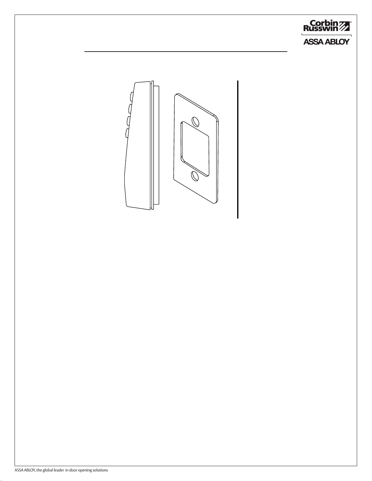
Wiring
Exit Holes
Controller
Backplate
Single
Gang Box
Holes
Installation and Wiring Instructions for Corbin Russwin WM800
2.2 Performing a Wall Mount Installation
Typically, the WM800 unit is mounted on a flat, surface (drywall, masonry, wood, etc.).
A single-gang electrical box (or back box) can be used. Typically, the WM800 unit is
wall mounted outside the access area on the unsecure side of the door.
Figure 2 illustrates the backplate on the WM800 unit used for wall mounting. Two
single-gang box holes align with two corresponding holes in the single-gang box. A wire
exit knockout is supplied through which the WM800 wiring is pulled.
1. Secure a single-gang box to the desired location.
2. Punch out the two holes for single-gang box connectors (Figure 2) on the controller
backplate of the WM800 unit. Punch out wiring exit hole(s) as required.
3. Disconnect the controller backplate of the WM800 unit from the front
keypad/controller. Align the two single-gang box connectors on the controller
backplate over the two corresponding holes on the single-gang box, previously
secured at step 1.
4. Secure the backplate to the single-gang box by inserting/tightening two screws into
the two single-gang box holes. For exterior applications, install the supplied gasket
between the WM800 backplate and wall (Figure 3).
5. Pull the WM800 wiring through the wiring exit holes as appropriate.
6. Install the communication board onto the controller backplate using the supplied five
screws.
7. Refer to Wiring Instructions (section 3), to connect the communication board to the
main controller board and appropriate wiring for the application.
8. Connect the front keypad/controller to the back housing.
9. Install either the hex screw using the supplied hex wrench or the spanner screw
supplied in the hardware pack. Use a #6 spanner bit (not included) for the spanner
screw.
Figure 2 Backplate
Branding Guidelines For Installation Instruction Sheets
* Must Be Used On All Single Page and Multiple Page Installation Instruction Sheets
* Must Be Used On The Bottom Left Of
Installation Instruction Sheets
* Must Be Used On The Bottom Left Of
of Multiple Page Installation Instruction Sheets
On The Back Page Or Back Cover Of Installation Instruction Sheets
* Image Must Be Used - CANNOT Be Typed
Of All Multiple Page Installation Instruction Sheets
* Image Must Be Used - CANNOT Be Typed
* A 2 line Version and a 5 Line Version Of The Corporate Statement Image Are Available
* Must Be Used On The Bottom of
Installation Instruction Sheets
* Must Be Used On The Bottom of The
Of All Multiple Page Installation Instruction Sheets
Copyright © 2008 Corbin Russwin, Inc., an ASSA ABLOY Group company. All rights reserved.
Reproduction in whole or in part without the express written permission of Corbin Russwin, Inc. is prohibited.
Note: Marketing will continue to be part of the instruction sheet and template reviewing process